Abstract
A new single-capillary electrospray (ES) aerosol generator has been developed for monodisperse particle production with maximal transmission efficiency. The new generator consists of both a spray chamber in a point-to-orifice-plate configuration and a charge reduction chamber that can hold up to 4 Nuclespot ionizers (Model P-2042, NRD Inc.). The 2 chambers are partitioned by an orifice plate. To optimize the particle transmission efficiency of the prototype, a systematic study was performed on the generator by varying the system setup and operation. Two key dimensions of the generator setup, the orifice diameter and the distance from the capillary tip to the orifice plate, were varied. Fluorescence analysis was applied to characterize the loss of ES-generated particles at different locations of the prototype. It was found that particle loss in the generator could be reduced by either increasing the orifice diameter or decreasing the distance between the capillary tip and the orifice plate. Increasing either the total radioactivity of the ionizers or the flowrate of the particle carrier gas also further decreased the particle loss in the system. The maximum particle transmission efficiency of 88.0% was obtained with the spray chamber fully opened to the charge reduction chamber, the capillary tip at the same level as the orifice plate, and 4 bipolar ionizers installed.
INTRODUCTION
Electrohydrodynamic spraying (i.e., electrospray [ES]) uses electric forces to atomize liquids. In ES, the liquid flowing out of a capillary nozzle is forced into fine droplets when the local liquid surface tension is overcome by the electric forces at the surface of the liquid. The basic forms of ES include single-capillary ES, dual-capillary ES, and tri-nozzle ES (Chen et al. 1995; Mei and Chen 2007; Lee et al. 2011). The operational mode of single-capillary ES has been well investigated and summarized (Cloupeau and Prunetfoch 1994; Jaworek and Krupa 1999; de la Mora 2007; Marginean et al. 2007). Among all the operational modes, the so-called cone-jet mode, capable of generating monodisperse particles in diameters ranging from nanometers to micrometers, has attracted much attention in particle research and applications. Unlike mechanical spray techniques, ES can generate particles within a narrow size range, and the particle size can be varied by changing the liquid conductivity, liquid flowrate, and solute concentration without degrading the particles’ chemical or biological properties (Chen and Pui 1997; Ganan-Calvo 1997; Hartman et al. 2000). Examples of ES applications include drug delivery, nanoparticle material synthesis, thin film deposition, and particle encapsulation (Chen et al. 1995; Ciach 2007; Jaworek 2007; Mei and Chen 2007; Jaworek and Sobczyk 2008; Peltonen et al. 2010). However, the low particle transmission efficiency with existing ES systems has not been fully addressed. Based on the experimental evaluation previously done by one of the authors, a commercial electrospray aerosol generator system typically has only 30–40% particle transmission efficiency. This becomes significant for applications in which the mass concentration of particles is critical, such as targeted medicine delivery, particle material synthesis and recovery, and nanoparticle toxicity studies.
The transport behavior of ES-generated droplets emitted from the jet break-up has been investigated (Ganan-Calvo et al. 1994; Gomez and Tang 1994; Hartman et al. 1999). Most studies on particle transport in ES processes, however, have focused on droplet behavior in the spray plume. In the radial direction of the plume, the spray is at first very narrow. Because of the mutual repulsion of highly charged droplets, it then spreads significantly as droplets move toward the counter electrode. More, it has been observed that particles of smaller sizes move toward the edge of the spray due to their high electrical mobility when compared with particles of large sizes (Ganan-Calvo et al. 1994). In the axial direction of the plume, the velocity of ES-generated particles is mainly attributed to the electric field strength between the capillary and counter electrode plate. It is, therefore, easy for highly charged droplets to be deposited on the counter electrode. The above spray behavior is advantageous for thin film preparation via electrospray. However, for aerosol applications, ES-generated particles must remain airborne prior to their use. Therefore, the electrical charge level on ES-generated particles needs to be reduced for further transportation. In general, the charge level of ES-produced particles can be reduced by passing them through an environment where bipolar ions are produced via corona discharge, soft X-ray, or radioactive materials (Chen et al. 1995; Ebeling et al. 2000; Hogan et al. 2004). However, beyond these generalizations, information about the particle transmission efficiency of electrospray systems is very limited. In fact, most documented ES systems are not optimized to achieve high particle transmission efficiency. Further, to the authors’ knowledge, there has been no thorough investigation into the particle loss in an ES system via variation of the system setup and operational parameters.
In this study, we developed a new single-capillary electro-spray aerosol system to achieve high particle transmission efficiency. The performance of this new electro-spray system, especially the particle transmission efficiency, was optimized via variations of the system design, operational flowrate of carrier gas, and strength of radioactive material used. We also modeled the electric field in various system configurations to assist in the interpretation of experimental observations. The modeling results are included in the supplemental information.
EXPERIMENTAL SETUP AND METHODS
The newly designed single-capillary ES aerosol system in this study consisted of both spray and particle charge reduction chambers. A point-to-orifice-plate arrangement was used in the spray chamber, which was made of transparent plexiglass. A stainless steel capillary with an I.D. of 0.012″ and O.D. of 1/32″ was fixed on a holding plate that was installed at the top of the spray chamber, with the capillary in line with the center of the orifice plate. The distance between the capillary tip and the orifice plate could be adjusted from 0 to 1/4″ by inserting 1/32″ thick spacers. Plates with orifices of 3 diameters (1/4″, 3/4″, and 5/4″ D) were tested in the study. All of the orifice plates were 3/16″ thick. The transparent plexiglass spray chamber enabled observation of the spray condition via an optical system including an illumination light source, a microscope lens (Infinivar CFM-2/S™ Microscope Video Lenses, Edmund Optics Inc., Barrington, NJ), and a CCD (charge-coupled device) camera (Model XCD-SX910CR, SONY). The charge reduction chamber was designed to hold up to 4 spot ionizers (Po210, Nuclespot P-2042, NRD LLC, Grand Island, NY). A cylindrical opening with a 5/4″ diameter was the working zone in the charge reduction chamber. The axial distance between the upper edge of the ionizer and the lower surface of the orifice plate was 5/16″. The above distance was chosen to ensure that high-energy a particles emitted from Po210 sources did not reach the tip of the spray capillary. As a result, the bipolar ions in the spray chamber neutralized the particles: no influences on the spray were observed.
During operation, a positive high voltage was applied at the capillary tube via a high voltage DC power supply (Bertan, Series 230, Spellman High Voltage Electronics Corporation, Valhalla, NY). The orifice plate and charge reduction chamber were electrically grounded. The spray solution was introduced into the capillary tube by a syringe pump (Model PHD 2000, Harvard Apparatus, Holliston, MA). Filtered air was introduced into the spray chamber as particle carrier gas. The carrier gas flowrate was controlled by a needle valve and monitored by a laminar flow meter. Note that an optional flow channel was designed in the system to introduce sheath gas flow around the capillary tip when spraying solutions with high surface tension, such as aqueous solutions. This option, however, was not needed for this study.
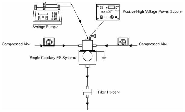
Figure 1 is a schematic diagram of the experimental setup. The ES system was operated in a stable cone-jet mode to generate monodisperse particles. The liquid feed flow rate was fixed at 1 μl/min, and the applied positive voltage was around 4 kV relative to the electrically grounded orifice plate. Two flowrates of particle carrier air (1.5 and 6.0 lpm) were tested. At the exit of the charge reduction chamber, a 47 mm filter holder (Millipore, Billerica, MA) with high efficiency particulate air (HEPA) filter media (Lydall Filtration/Seperation, Inc., Rochester, NH) collected all the particles exiting from the ES system.
FIG. 1.
Schematic diagram of experimental setup to characterize the transmission loss of particles generated by the single-capillary ES system.
Fluorescence analysis was used to characterize the particle loss at various locations of the ES system (Chen and Pui 1995). Uranine was the fluorescent tracer for the quantitative analysis of deposited particles. The electrospray solution was prepared by dissolving 0.1% (v/v) sucrose and 1 g/L uranine in a 2-propanol/water mixture. Each experimental run lasted for 60 min.
After each run, particles deposited at various locations in the ES system were washed off by an aqueous solution of 0.001 N ammonium hydroxide. The uranine deposited on the orifice plate (MP late) was recovered by wiping the surface with cotton swabs wetted in the wash solution. The uranine on the cotton swabs was then dissolved in 25 ml of wash solution. The uranine deposited in the charge reduction chamber (MChamber) was recovered in the same way. The mass of the uranine collected on the filter was measured by immersing the entire filter medium in 25 ml of the wash solution. The uranine deposited on the wall of the tubing connecting the ES system with the HEPA filter was also recovered by cotton swabs, which were then immersed in the same wash solution as the filter. Thus, MF ilter included the uranine that survived passage through the ES system. The concentration of uranine in the various wash solutions was measured by a calibrated fluorometer (GloMax®-Multi Jr Single Tube Multimode Reader, Promega Corporation, CA). For each experimental run, we further checked the mass conservation of uranine by comparing the amount of uranine recovered from various locations in the generator with the total amount of uranine sprayed. In general, the difference between sprayed and recovered amounts was within 5% of the total sprayed.
The transmission efficiency of ES-produced particles was then calculated by Equation (1):
| [1] |
RESULTS AND DISCUSSION
The ES that operates in the cone-jet mode can generate monodisperse particles with diameter varying from nanometer to micrometer. Because particles produced by ES are highly charged, significant particle loss in the system is expected, owing to the presence of the strong DC electrical field for the spray and the mutual repulsion among highly charged particles. Reducing the electric charge of ES-generated particles will help keep them airborne. The transmission efficiency of the studied ES aerosol generator was influenced by factors including the system setup configuration, particle carrier gas flowrate, and the strength of the radioactive sources. In this study, the particle transmission efficiency was characterized under these factors.
Effects of Orifice Diameter and Capillary-to-Plate Distance
The orifice ratio, defined as the ratio of the orifice diameter to the diameter of the charge reduction chamber, was used to characterize the effect of orifice diameter on the transmission efficiency of the ES generator. Three plates were tested, with orifice ratios of 1:5 (plate #1; 1/4″ D), 3:5 (plate #2; 3/4″ D), and 1:1 (plate #3; 5/4″ D). The transmission efficiency was characterized at a carrier gas flowrate of 6.0 lpm, with 4 ionizers installed in the charge reduction chamber. No spacer was used for this part of the experiment, so the spray capillary tip was at the same level as the upper surface of the orifice plate. Figure 2 shows the transmission efficiencies as a function of the orifice ratios.
FIG. 2.
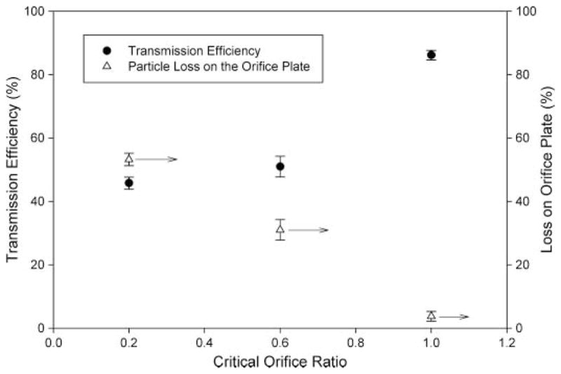
Transmission efficiency and particle loss on the orifice plate for different orifices.
Under the given experimental conditions, approximately 45.8% of particles generated by the single-capillary ES penetrated through the system when plate #1 was installed. The transmission efficiency increased with larger orifices. Compared to the case with plate #1, the transmission efficiency of the aerosol generator was almost doubled (i.e., 86.2%) by using plate #3. Also shown in Figure 2 is the percentage of particles deposited on the orifice plate. With increased orifice diameters, the particle loss on the plate decreased from 53.3% for plate #1 to 3.7% for plate #3.
In addition to the orifice size, another dimension in the system setup was the distance between the tip of the capillary and the upper surface of the orifice plate. In our system, the distance could be adjusted by the spacers. The experimental results for this part of the study are shown in Figure 3. Four ionizers were installed in the charge reduction chamber of the ES generator for these experiments. Recall that with no spacer, plate #1 (1/4″ D) had a transmission efficiency of 45.8% at a carrier gas flowrate of 6.0 lpm. When a 1/4″ spacer was installed, the efficiency at the same flowrate dropped to 11.0%. For plate #3 (5/4″ D), at a gas flowrate of 1.5 lpm, spacers of 1/8″ and 1/4″ thicknesses resulted in transmission efficiencies of 84.9% and 70.1%, respectively. When no spacer was installed, the transmission efficiency for plate #3 was 88.0%. The particle transmission efficiency of the studied ES generator was again decreased by larger distances between the capillary tip and orifice plate.
FIG. 3.
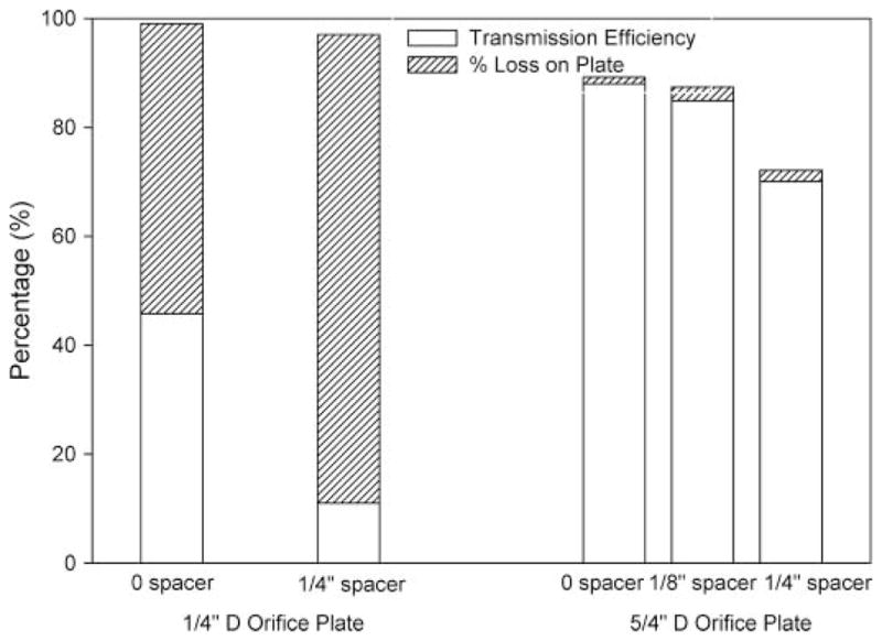
Effect of the spacers and orifice plate on transmission efficiency and particle loss on the orifice plate.
For an ES setup in the point-to-orifice-plate configuration, the electrical field is present in both the spray and charge reduction chambers. The movement of ES-generated droplets results from the flow and electrical fields, the charges on particles, and the gravity of large particles. In general, because of the DC electrical field, particles generated by ES are highly charged with the same polarity. When the electrical field is sufficiently strong, charged droplets are most likely moving in the field direction. When no spacer is used (i.e., the tip of the capillary is in the plane of the orifice plate), the steepest decrease in electrical potential is in the radial direction, from the capillary tip to the edge of the orifice. The gradient of electrical potential decreases with an increase of the orifice diameter. The percentage of the particles lost on the orifice plate thus decreased as the orifice diameter varied from 1/4″ to 5/4″.
When a spacer was used, the capillary tip was located above the orifice plate. Highly charged droplets generated by ES had to first travel through the spray chamber, pass the orifice plate, and enter into the charge reduction chamber, where the particle charge level could be reduced by exposing them to bipolar ions produced by the radioactive sources (Po210). For the case of the 1/4″ D orifice plate, the larger the distance between the capillary tip and orifice plate, the longer the distance droplets had to travel. Consequently, more droplets were likely deposited on the orifice plate. With the 5/4″ D orifice plate, the gradient of the electrical potential was much less than for the case with the 1/4″ D orifice plate. Therefore, the movement of charged droplets in the radial direction was much slower, giving more time for charge reduction. The result was a reduction of particle deposition on the orifice plate. In fact, with 5/4″ D orifice plate, most of the particle loss was in the charge reduction chamber.
Effect of Radioactive Source Strength
Particles generated by ES are highly charged, especially when spraying liquids of high electrical conductivity. ES-produced particles thus tend to follow the electrical field and deposit on the counter electrode (i.e., orifice plate). For applications in which the collection or deposition of particles is essential, the particle collection efficiency can be increased by grounding or applying minor voltage of reverse polarity on the collector, consequently decreasing the particle loss. However, some applications, such as aerosol drug delivery, require particles to remain airborne. In such applications the above methodology will not improve the particle transmission efficiency of the studied generator. To reduce the particle loss due to the electrostatic force, charges on ES-generated particles must be reduced. Several charge reduction techniques, such as corona discharge, radioactive sources, and soft X-ray irradiation, could be applied in ES systems. Using a radioactive source is an effective and reliable way to electrically neutralize charged particles (Liu and Pui 1974). In this study, 210Po α ionization sources (Model P-2042; NRD Inc.) were used in the charge reduction chamber, which could simultaneously hold up to 4 ionizers. The bipolar ion concentration in the chamber, N0, which increases with the radioactive strength, can be estimated as follows (Vivas et al. 2008):
| [2] |
where A0 is the activity of the radioactive source, E is the energy of the α particles, αr is the ion recombination coefficient (1.6 × 10⁻¹² m3s−1), W is the mean ionization potential of air (35 eV), and V is the volume of the charge reduction chamber. The original activity of the Nuclespot ionizers was 5.0 mCi. The actually activity can thus be calculated based on the half-life of 210Po, which is 138 days:
| [3] |
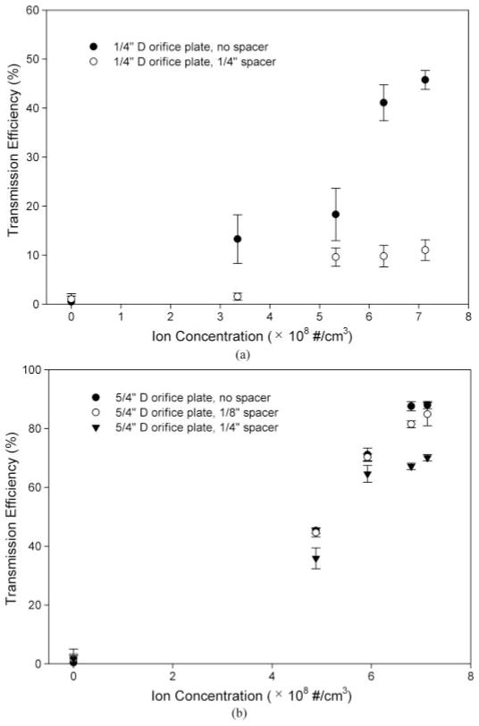
In this part of study, the effect of the ion concentration on the particle transmission efficiency of ES-produced particles was studied by varying the number of sources installed in the charge reduction chamber. Figure 4 shows the transmission efficiency of the generator as a function of ion concentration at a carrier gas flowrate of 6.0 lpm. The data for the cases with Plate #1 (1/4″ D) and #3 (5/4″ D) are compared. In both cases, the transmission efficiency increased with an increase in bipolar ion concentration. When no ionizer was installed, ES-produced particles were more likely to follow the electrical field and be deposited on the grounded surfaces (i.e., the surfaces of the orifice plate and the inner surface of the charge reduction chamber). As a result, the measured particle transmission efficiency was less than 5% for both orifice plate cases. With only 1 ionizer in the prototype, the percentage of ES-produced particles that exited the system were 37.4% for the 5/4″ D orifice and 13.3% for the 1/4″ D orifice, respectively. The particle transmission efficiency kept increasing with an increase in bipolar ion concentration. When more ionizers were used, the bipolar ion density in the charge reduction zone was increased, thus increasing the chance to reduce the charges on ES-produced particles. As shown in Figure 4, the particle transmission efficiency was doubled when the ion concentration increased from about 4.9 × 10⁸ #/cm3 to over 5.9 × 10⁸ #/cm3. However, as the ion concentrations increased from 5.9 × 10⁸ #/cm3 to 7.1 × 10⁸ #/cm3, the particle transmission efficiency increased by less than 10%. The average charges associated with ES-produced particles are directly related to the spray current, which remained constant in our study (the sprayed solutions had the same electrical conductivity). Thus, for a certain average charge level, there existed a minimum ion concentration required to effectively reduce charges on most ES-produced particles. For the given experimental conditions, to reach over 80% of the highest transmission efficiency, the ion concentration was larger than 5.9 × 10⁸ #/cm3, corresponding to more than 2 ionizers used in the prototype. The half-life of Po210 is about 138 days. Using at least 3 ionizers with a total radioactivity larger than 4 mCi is thus recommended for the studied ES generator.
FIG. 4.
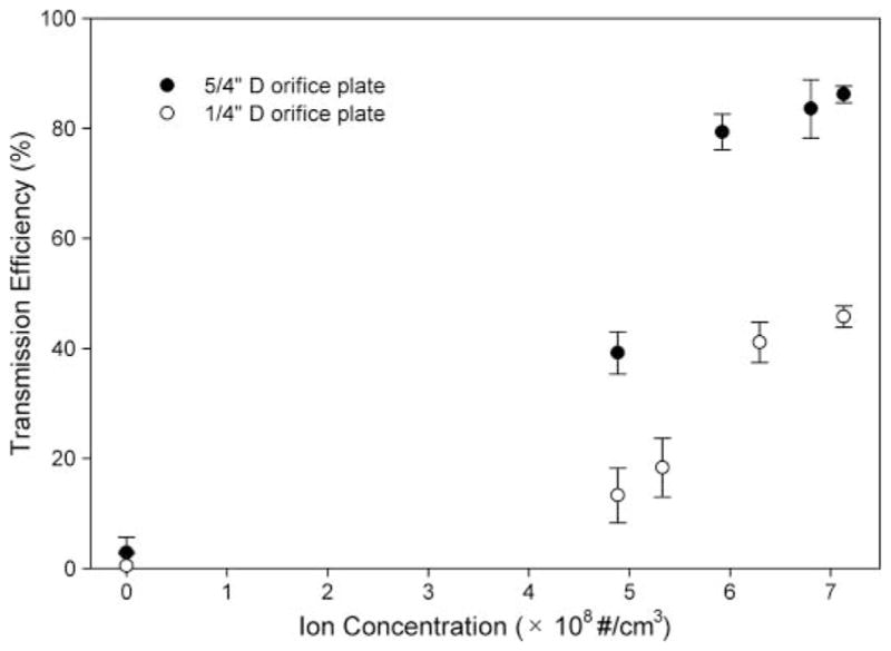
Transmission efficiency as a function of bipolar ion concentration. The flow rate of carrier gas was 6 lpm. No spacer was used.
Similarly, Figure 5 shows the transmission efficiency of ES-produced particles as a function of ion concentration for the cases of (a) the 1/4″ D orifice plate with spacers, and (b) the 5/4″ D orifice plate with spacers. For all spacer cases, the transmission efficiency increased with an increase in bipolar ion concentration. Moreover, the increases in the transmission efficiencies for the cases when the ion concentration was larger than 6 × 10⁸ #/cm3 were all within 5%. For cases with both 1/4″ D and 5/4″ D orifice plates, at a given ion concentration, the use of a spacer increased the particle loss, which is in agreement with the modeling result. Note that the particle transmission efficiency did not vary much for the cases using a 5/4″ D orifice plate (with/without spacers installed). In contrast, a significant difference in the efficiency was observed for the cases using a 1/4″ D orifice plate (with/without spacers).
FIG. 5.
Transmission efficiency as a function of bipolar ion concentration: (a) using orifice plate together with spacers, and (b) using 5/4″orifice plate together with spacers.
Effect of Carrier Gas Flowrate
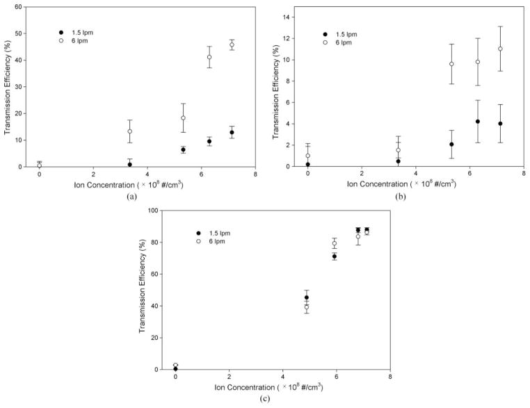
In addition to the bipolar ion concentration, the other factor affecting the charge reduction process is the particle residence time in the charge reduction chamber. The residence time is controlled by the flowrate of particle carrier gas. We used particle carrier gas flowrates of 1.5 lpm and 6.0 lpm, corresponding to residence times of 1.6 s and 0.4 s, respectively. The Reynolds numbers in the ES system were 67 and 267 for 1.5 lpm and 6.0 lpm flow, respectively, indicating that the flow was mostly laminar in the system. Figure 6a shows the transmission efficiency as a function of bipolar ion concentration for the ES generator with the 1/4″ D orifice plate and without a spacer. Figure 6b is for the system with the 1/4D orifice plate and a spacer of 1/4″ thickness, and Figure 6c is for the 5/4″ D orifice plate without a spacer.
FIG. 6.
Effects of carrier gas flowrate on transmission efficiency as a function of bipolar ion concentration. (a) 1/4″ D orifice plate, no spacer; (b) 1/4″ D orifice plate, 1/4″ pacer; and (c) 5/4″ D orifice plate, no spacer.
For the 1/4″ D orifice plate, the transmission efficiency at a carrier gas flowrate of 6.0 lpm was much improved over that at 1.5 lpm. The transmission efficiency for the generator with the 1/4″ D orifice plate, operated at the 1.5 lpm air flowrate, was less than 15%, even with 4 ionizers installed. However, as indicated in Figure 6c, the improvement between the cases with the 1/4″ D orifice plate was not observed with the 5/4″ D orifice plate.
With the 1/4″ D orifice plate installed in the studied ES generator, the spray and charge reduction chambers were separated. Charges on ES-generated particles could not be efficiently reduced before they entered the charge reduction chamber. The major particle loss for the generator with the 1/4″ D orifice plate was thus attributed to particle deposition on the orifice plate. By operating the ES system at a high flowrate, the gas flow velocity was increased and the particle residence time was decreased, leading to less deposition of charged droplets on the orifice plate.
The bore of the spray and charge reduction chambers are each cylinders with an inner diameter of 5/4″. When the 5/4″ D orifice plate was installed in the system, the 2 chambers were effectively merged into 1. The distance between the capillary tip and the chamber wall was at least 5/8″. Under the given ion concentration, the long travel distance increased the chance for particles to be charge-reduced prior to their deposition on the orifice plate. At the same time, their residence time was decreased when the flowrate of carrier gas was increased. The chance for ion-particle interaction was decreased, leading to an increase in particle loss due to ineffective charge reduction. The overall particle transmission efficiency of the studied system was the result of the 2 competitive factors described earlier. Figure 6c shows that the particle transmission efficiencies at 2 carrier gas flowrates were nearly the same for the system with the 5/4″ D orifice plate, indicating that the carrier gas flowrate did not significantly affect the particle transmission. It is possible that the effect of residence time decrease on the transmission efficiency was offset by that of the long particle travel distance in the system prior to their deposition.
Note that we tried to plot the transmission efficiency as a function of the Nit value since the product of the ion concentration Ni and residence time t is normally used as the key parameter in neutralization/charging theories. However, no simple correlation could be found in all the studied cases, indicating that other factors, for example, spatial distribution of ions and chamber geometry, play roles in the loss of ES-generated particles.
Effect of Particle Loss on the Size Distribution of ES-generated Particles
As shown in the previous section, the particle loss in the studied ES system depends on the system setup and operation. We wanted to check whether or not the particle loss affected the size distribution of particles generated. We thus characterized the size distribution of particles using a scanning mobility particle sizer (SMPS, Model 3080, TSI Inc., St Paul, MN) for various system setups and operating conditions. All the data obtained in this part of the experiment were obtained from systems with 4 bipolar ionizers installed.
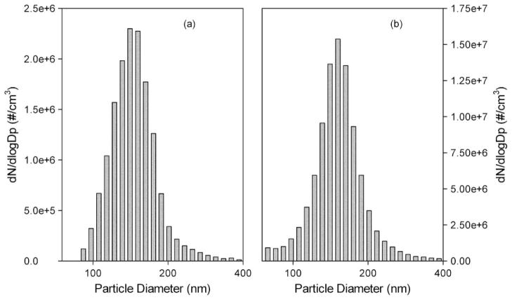
Two typical size distributions are shown in Figure 7. Figure 7a is the size distribution for the case with low particle transmission efficiency (4.0%): the system was operated with the 1/4″ orifice plate and 1/4″ spacer installed (1.5 lpm flowrate). Figure 7b gives the size distribution of particles generated from the system with high particle transmission efficiency (86.2%), with the 5/4″ D orifice plate, and no spacer installed (6.0 lpm flowrate).
FIG. 7.
Particle size distribution generated by the designed ES system: (a) 1/4″ D orifice plate, 1/4″ spacer, 1.5 lpm; and (b) 5/4″ D orifice plate, no spacer, 6 lpm.
The geometric mean diameters and geometric standard deviations for the size distributions in Figure 7 were 145.9 nm and 1.20 for Figure 7a, and 153.7 nm and 1.20 for Figure 7b. The primary particle size distributions are similar in shape for all the tested cases. In general, the monodispersity of generated particles remained good, confirming that the distribution of primary particles was not affected in our system optimization for maximal particle transmission efficiency. The major difference between the distributions was that the case of high particle transmission efficiency (Figure 7b) had more particles with smaller diameters than the low efficiency case (Figure 7a). It is known that particles generated in ES move with different velocities in the radial direction of the spray. Due to their high electrical mobility, more smaller particles moved toward the edge of the spray than the larger particles (Ganan-Calvo et al. 1994). As a result, the loss of smaller particles increased significantly when the orifice diameter was decreased. As shown in Figure 7, more particles with smaller diameters passed through the ES system with the 5/4″ D orifice, while the primary particle size distribution remained similar in shape.
CONCLUSION
A prototype single-capillary electrospray aerosol generator in point-to-orifice-plate configuration was constructed and optimized to achieve high transmission efficiency of produced particles. A systematic study was performed by varying the system setup and flowrate operation. Two key dimensions were varied, the orifice diameter of the counter electrode plate and the distance between the capillary tip and the plate. Fluorescence analysis was used to quantify the particle loss at different locations of the prototype under various setups and operating conditions. Numerical modeling of the electrical field at different system setups was also performed to assist in interpreting the experimental observations. It was found that the particle loss could be significantly reduced by increasing the orifice diameter and/or decreasing the distance between the capillary tip and orifice plate. The particle transmission efficiency of the studied ES system could be further improved by increasing either the ionizing radioactivity or the flowrate of carrier gas. It was concluded that 2 radioactive ionizers with a total radioactivity larger than 4 mCi would be sufficient for the prototype. The flowrate of particle carrier gas more significantly influenced the system with the 1/4″ D orifice plate than that with the 5/4″ D orifice plate, possibly because of the balance between the charge reduction process and particle transportation in the prototype. The quality of particles generated by the prototype ES system was also examined by SMPS, and measured primary particle peaks were not affected by particle loss. Thus, the prototype generated particles with good monodispersity while achieving high particle transmission efficiency. The highest particle transmission efficiency, 88.0%, was achieved with the spray chamber fully open to the charge reduction chamber, the capillary tip at the same level as the orifice plate, and 4 bipolar ionizers installed. The knowledge obtained in this study provides general guidance for the system setup of single-capillary electrospray to achieve high transmission efficiency. It may also provide basic guidelines for the system setup in multiplexing ES.
Supplementary Material
Footnotes
Disclosure of Potential Conflicts of Interest: Da-Ren Chen is a consultant and one of cofounders for Nanocopoeia Inc., St. Paul, MN. Chen may receive income based on equity holdings in Nanocopoeia Inc., although Nanocopoeia did not support this work.
References
- Chen DR, Pui DYH. Experimental Investigation of Scaling Laws for Electrospraying: Dielectric Constant Effect. Aerosol Sci Tech. 1997;27:367–380. [Google Scholar]
- Chen DR, Pui DYH, Kaufman SL. Electrospraying of Conducting Liquids for Monodisperse Aerosol Generation in the 4 Nm to 1.8 Mu-M Diameter Range. J Aerosol Sci. 1995;26:963–977. [Google Scholar]
- Ciach T. Application of Electro-hydro-dynamic Atomization in Drug Delivery. J Drug Deliver Sci Technol. 2007;17:367–375. [Google Scholar]
- Cloupeau M, Prunetfoch B. Electrohydrodynamic Spraying Functioning Modes – a Critical-Review. J Aerosol Sci. 1994;25:1021–1036. [Google Scholar]
- de la Mora JF. The Fluid Dynamics of Taylor Cones. Annu Rev Fluid Mech. 2007;39:217–243. [Google Scholar]
- Ebeling DD, Westphall MS, Scalf M, Smith LM. Corona Discharge in Charge Reduction Electrospray Mass Spectrometry. Anal Chem. 2000;72:5158–5161. doi: 10.1021/ac000559h. [DOI] [PubMed] [Google Scholar]
- Ganan-Calvo AM. Cone-jet Analytical Extension of Taylor’s Electrostatic Solution and the Asymptotic Universal Scaling Laws in Electrospraying. Phys Rev Lett. 1997;79:217–220. [Google Scholar]
- Ganan-Calvo AM, Lasheras JC, Davila J, Barrero A. The Electrostatic Spray Emitted from an Electrified Conical Meniscus. J Aerosol Sci. 1994;25:1121–1142. [Google Scholar]
- Gomez A, Tang KQ. Charge and Fission of Droplets in Electrostatic Sprays. Phys Fluids. 1994;6:404–414. [Google Scholar]
- Hartman RPA, Brunner DJ, Camelot DMA, Marijnissen JCM, Scarlett B. Electrohydrodynamic Atomization in the Cone-jet mode Physical Modeling of the Liquid Cone and Jet. J Aerosol Sci. 1999;30:823–849. [Google Scholar]
- Hartman RPA, Brunner DJ, Camelot DMA, Marijnissen JCM, Scarlett B. Jet Break-up in Electrohydrodynamic Atomization in the Cone-jet Mode. J Aerosol Sci. 2000;31:65–95. [Google Scholar]
- Hogan CJ, Lee MH, Biswas P. Capture of Viral Particles in Soft X-ray-enhanced Corona Systems: Charge Distribution and Transport Characteristics. Aerosol Sci Tech. 2004;38:475–486. [Google Scholar]
- Jaworek A. Electrospray Droplet Sources for Thin Film Deposition. J Mater Sci. 2007;42:266–297. [Google Scholar]
- Jaworek A, Krupa A. Classification of the Modes of EHD Spraying. J Aerosol Sci. 1999;30:873–893. [Google Scholar]
- Jaworek A, Sobczyk AT. Electrospraying Route to Nanotechnology: An Overview. J Electrostat. 2008;66:197–219. [Google Scholar]
- Lee YH, Bai MY, Chen DR. Multidrug Encapsulation by Coaxial Tri-capillary Electrospray. Colloid Surface B. 2011;82:104–110. doi: 10.1016/j.colsurfb.2010.08.022. [DOI] [PubMed] [Google Scholar]
- Liu BYH, Pui DYH. Electrical Neutralization of Aerosols. J Aerosol Sci. 1974;5:465–472. [Google Scholar]
- Marginean I, Nemes P, Vertes A. A stable Regime in Electro-sprays. Phys Rev E. 2007;76:6. doi: 10.1103/PhysRevE.76.026320. [DOI] [PubMed] [Google Scholar]
- Mei F, Chen DR. Investigation of Compound Jet Electrospray: Particle Encapsulation. Phys Fluids. 2007;19:1–10. [Google Scholar]
- Peltonen L, Valo H, Kolakovic R, Laaksonen T, Hirvonen J. Electrospraying, Spray Drying and Related Techniques for Production and Formulation of Drug Nanoparticles. Expert Opin Drug Del. 2010;7:705–719. doi: 10.1517/17425241003716802. [DOI] [PubMed] [Google Scholar]
- Vivas MM, Hontanon E, Schmidt-Ott A. Design and Evaluation of a Low-level (0.24 mu Ci) Radioactive Aerosol Charger Based on Am-241. J Aerosol Sci. 2008;39:191–210. [Google Scholar]
Associated Data
This section collects any data citations, data availability statements, or supplementary materials included in this article.


