Abstract
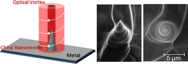
We discovered for the first time that light can twist metal to control the chirality of metal nanostructures (hereafter, chiral metal nanoneedles). The helicity of optical vortices is transferred to the constituent elements of the irradiated material (mostly melted material), resulting in the formation of chiral metal nanoneedles. The chirality of these nanoneedles could be controlled by just changing the sign of the helicity of the optical vortex. The tip curvature of these chiral nanoneedles was measured to be <40 nm, which is less than 1/25th of the laser wavelength (1064 nm). Such chiral metal nanoneedles will enable us to selectively distinguish the chirality and optical activity of molecules and chemical composites on a nanoscale and they will provide chiral selectivity for nanoscale imaging systems (e.g., atomic force microscopes), chemical reactions on plasmonic nanostructures, and planar metamaterials.
Keywords: Metal nanoneedle, laser ablation, optical vortex, chirality, singular optics
Chiral twisted metal nanoneedles will enable us to selectively distinguish the chirality1,2 and optical activity of molecules and chemical composites on a nanoscale and they have the potential to provide chiral selectivity to nanoscale imaging systems (e.g., atomic force microscopes and scanning tunnel microscopes),3,4 chemical reactions on plasmonic nanostructures,5,6 and planar metamaterials.7
However, no technique has been developed for twisting metal on a nanoscale and controlling chiral metal nanoneedles, even by utilizing advanced chemical techniques.8 Laser material processing,9,10 which employs high-intensity laser pulses to break down a target into its constituent elements, is unsuitable for recombining the constituent elements and fabricating structured materials. To date, laser material processing has not been used to produce chiral metal nanoneedles.
Optical vortices11−15 with helical wavefronts and a doughnut spatial form due to a phase singularity expressed by Lφ (where L is an integer known as the topological charge and φ is the azimuthal angle) in the transverse plane carry orbital angular momentum (L). Circularly polarized light also has a spin (S) angular momentum. Consequently, circularly polarized optical vortices carry a helicity known as the total angular momentum (J = L + S), which is given by the vector sum of the orbital (L) and spin (S) angular momenta.11 This helicity has been widely applied in optical tweezers and it can be used to cause submicrometer particles to rotate in an orbit.16−19
In this study, we demonstrate that optical vortices can twist metal to form chiral metal nanoneedles. These chiral metal nanoneedles have a twisted conical surface and their chirality can be controlled by just changing the sign (direction) of the optical vortex helicity. The minimum tip curvature of the nanoneedles was extremely small, being <40 nm, which is less than 1/25th of the laser wavelength (1064 nm).
We have previously reported that laser ablation using optical vortices with nonzero total angular momentum (which we term optical vortex laser ablation) produces metal needles.20,21 However, we did not completely characterize optical vortex laser ablation nor determine the needle formation mechanism. According to the model proposed in our previous studies, needles form due to the magnitude rather than the sign of the optical vortex helicity. Thus, we did not investigate the performance of optical vortex laser ablation by changing the sign of the optical vortex helicity. In this study, we discovered for the first time that the sign of the optical vortex helicity determines the chirality of nanoscale metal structures. The laser energy used in the present experiments was less than one-sixth (<0.3 mJ) that (2 mJ) used in our previous experiments. This low energy permits chiral nanoneedles to form; the chirality of fabricated nanoneedles disappears at higher energies.
The experimental setup is shown in Figure 1. The target was a ∼1-mm-thick polished tantalum (Ta) (complex dielectric constant is approximately −2.54 + 10i at 1064 nm22) plate, which has a relatively low ablation threshold compared with other metals.23 A conventional Q-switched Nd/YAG laser (Quanta-Ray, GCR190) with a wavelength of 1064 nm and a pulse duration of 30 ns was used as the pump laser. Its output was spatially filtered by a 5 mm diameter aperture in combination with a telescope to produce a plane wave beam. A spiral phase plate, fabricated by electron beam etching, was azimuthally divided into 16 parts by an nπ/8 phase shifter (where n is an integer between 0 and 15). A quarter-wave plate was placed in the optical path between the spiral phase plate and a focusing lens (NA = 0.08, 0.09, 0.13, and 0.18) to control the polarization of the optical vortex. To reverse the sign of the optical vortex helicity, the spiral phase plate and the quarter-wave plate were inverted. The pump laser energy in this experiment was controlled in the range 0.075–0.3 mJ; which is less than 1/sixth of the pump laser energies used in our previous experiments. The experiments were performed at atmospheric pressure and room temperature. The ablated surface of the Ta plate was observed by SEM (JEOL, JSM-6010LA) with a spatial resolution of 8 nm at 3 kV.
Figure 1.
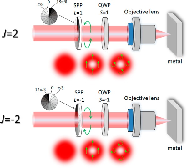
Schematic diagram of experimental setup. SPP, spiral phase plate; QWP, quarter-wave plate. To reverse the sign of the total angular momentum J, the SPP and QWP are inverted. A circularly polarized optical vortex pulse is focused onto a metal target by a focusing lens (NA = 0.08, 0.09, 0.13, and 0.18). The optical vortex pulse energy in this experiment was controlled in the range 0.075–0.3 mJ, which is less than one-sixth that used in our previous experiments.
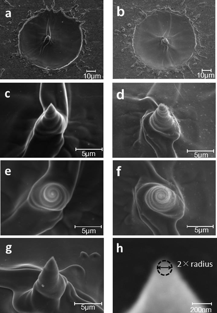
Figure 2 shows SEM images of a metal surface ablated by an optical vortex pulse with a total angular momentum of J = 2 or −2. The vortex beam was focused onto the target. It exhibited an annular spatial form with a diameter of ∼65 μm. Four vortex pulses were overlaid. A needle is created at the center of the ablated zone with a smooth outline (Figure 2a,b). The tip curvature and height of the needle were measured to be ∼72 nm and ∼10 μm, respectively. As shown in Figure 2h, to estimate the tip curvature, we fitted the tip with a circle by utilizing software installed on the SEM. The uncertainty in the measured values was approximately ±15%. As we found in a previous study,21 the nanoneedle height saturated when more than four pulses were superimposed on the surface (Figure 3a). Thus, we used four superimposed pulses in the present study.
Figure 2.
(a,c,e) SEM images of processed surface and a twisted nanoneedle fabricated by an optical vortex with a total angular momentum J of −2 (clockwise). (b,d,f) SEM images of processed surface and a twisted nanoneedle fabricated by optical vortex with a total angular momentum J of 2 (counter-clockwise). (c,d) The 25° views and (e,f) top views of the nanoneedle. (g) The 25° view of the nanoneedle formed using a pulse energy of 2 mJ. The chirality of the fabricated nanoneedle disappears. The focusing lens had an NA of 0.08. We estimated the tip curvature by fitting the tip with a circle utilizing software installed on the SEM, as shown in (h). The uncertainty in the measured values is approximately ±15%.
Figure 3.
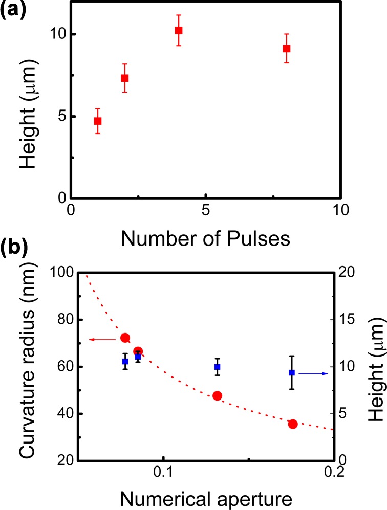
(a) Height of fabricated nanoneedle as a function of the number of superimposed pulses. Pulse energy and NA of the focusing lens were fixed to 0.3 mJ and 0.08, respectively. (b) Tip curvature and height of fabricated nanoneedle as a function of NA of the focusing lens. Fluence of the vortex pulse was fixed to ∼9 J/cm2.
As shown in Figure 2c (25° tilted view) and Figure 2e (top view), the conical surface of the needle was twisted azimuthally in the clockwise direction. In contrast, when an optical vortex with a total angular momentum J of 2 was used, a needle was fabricated at the center of the processed metal surface that was twisted azimuthally in the counter-clockwise direction. Thus, the sign of the helicity of the optical vortex pulse can selectively control the twisting direction (chirality) of the nanoneedle.
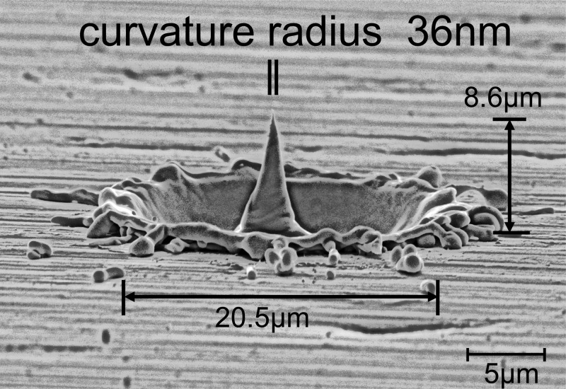
For an optical vortex with a total angular momentum J = 2, the tip curvature of the nanoneedle was found to be inversely proportional to the numerical aperture (NA) of the focusing lens according to conventional diffraction theory. The minimum tip curvature was measured to be ∼36 nm (Figure 3b), which is less than 1/25th of the laser wavelength (1064 nm). The height of the nanoneedle relative to the target surface was in the range 7.5–11.5 μm. Figure 4 indicates that the fabricated nanoneedle has a twisted conical surface, although the image quality is limited by the spatial resolution (∼8 nm) of the SEM.
Figure 4.
Side view of nanoneedle fabricated by an optical vortex with J = 2 produced using a focusing lens with an NA of 0.18. The nanoneedle had a tip curvature of 36 nm and a height of 8.6 μm. The conical side of the needle is twisted.
At energies above millijoule level, the chirality of the fabricated nanoneedle disappeared, as shown in Figure 2g. When the pulse energy is sufficiently high, the leading edge of the optical vortex pulse creates a dense plasma (vaporized material), which blocks the rest of the optical pulse. Thus, the angular momentum of the optical vortex is not sufficiently transferred to the melted material, thereby preventing the formation of chiral nanoneedles. The long confocal length (>100 μm) of the focused optical vortex, which is due to the low NA of the objective lens, made the nanoneedle parameters relatively insensitive to the focusing of the optical vortex pulse and it also suppressed the generation of a longitudinal electric field along the z-axis. Since laser ablation was performed at atmospheric pressure and room temperature, the nanoneedle may be composed of both the metal and its oxide, so it may exhibit a relatively high electrical resistance. The electrical properties of the nanoneedle were investigated by measuring the electrical resistance between the nanoneedle and a metal substrate using two 50 μm diameter tungsten probes with an internal resistance of ∼1.0 Ω. One probe was gradually moved toward the top of the nanoneedle, while the other was tightly pressed against the substrate surface to minimize the contact resistance. Figure 5 shows the current–voltage characteristics between the nanoneedle and the substrate (physical distance: ∼200 μm). The current was directly proportional to the voltage. The measured resistance was ∼1.05 Ω, which is identical to that of the substrate. The actual resistance excluding the internal resistance of the probe was estimated to be ∼50 mΩ. Energy-dispersive X-ray (EDX) spectroscopy was used to estimate the relative amounts of the chemical components of the nanoneedle. As shown in Figure 6, the EDX spectrum of the fabricated needle (shown by the red line) is almost identical to that of the substrate surface (shown by the black line). This indicates that the nanoneedle and the substrate had the same chemical compositions. These results indicate that the fabricated needle is perfectly metallic so that it can potentially be applied as an electrode in nanoimaging techniques such as atomic force microscopy, scanning tunnel microscopy, and plasmonic probes.
Figure 5.
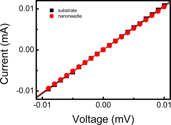
(Red) Current against applied voltage between nanoneedle and substrate measured using two 50 μm diameter tungsten probes. (Black) Current against applied voltage of substrate measured using two 50 μm diameter tungsten probes.
Figure 6.
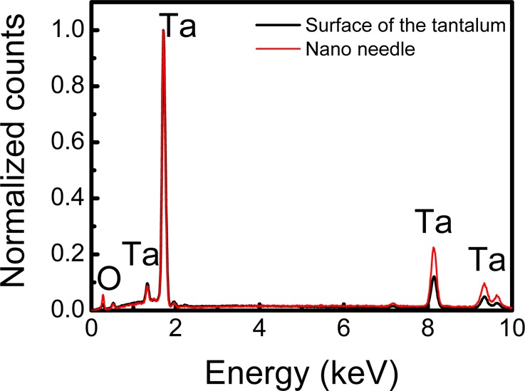
EDX spectra of nanoneedle and substrate.
The above results strongly support the following model. The focused vortex pulse breaks the metal down into its constituent elements (melted material). The optical vortex helicity is then transferred to the melted material, causing it to rotate azimuthally about the annular intensity profile of the optical vortex. (The estimated photon pressure was ∼1 nN.) This results in the formation of smooth processed surfaces with little debris. The angular momentum of the melted material is damped by friction and the material revolving about the optical axis of the optical vortex is efficiently directed toward the intensity hole (stable equilibrium position) of the optical vortex.24 The material accumulates at the center of the processed metal surface, producing a chiral needle. This model, which is based on angular momentum transfer from the optical vortex to the melted material, is evidenced by the observation that the conical surface of the needle is twisted azimuthally with the sign of the optical vortex helicity.
In conclusion, we have demonstrated for the first time that optical vortex laser ablation can twist metal to form chiral nanoneedles due to helicity transfer from the optical vortex to the melted metal. The chirality of the nanoneedles could be controlled by just changing the sign of the optical vortex helicity. The minimum tip curvature of fabricated needles with a height of 7.6 μm was measured to be <40 nm, which is less than 1/25th of the laser wavelength (1064 nm). Optical vortex laser ablation can produce chiral nanoneedles with extremely high aspect ratios (a nanoscale tip curvature with a height of the order of micrometers) rapidly and inexpensively. It has the potential to produce new technologies such as nanoimaging systems, energy-saving displays, and biomedical nanoelectromechanical systems. Chiral twisted nanostructures, which enable us to selectively distinguish the chirality and optical activity of molecules and chemical composites on a nanoscale, also have the potential to provide nanoscale imaging systems with a chiral selectivity, chemical reactions on plasmonic nanostructures, and planar metamaterials.
Acknowledgments
The authors acknowledge support from a Grant-in-Aid for Scientific Research (No. 21360026) from the Japan Society for the Promotion of Science.
The authors declare no competing financial interest.
References
- Bradshaw D.; Claridge J. B.; Cussen E. J.; Prior T. J.; Rosseinsky M. J. Design, chirality, and flexibility in nanoporous molecule-based materials. Acc. Chem. Res. 2005, 38, 273–282. [DOI] [PubMed] [Google Scholar]
- Yao Z.; Ch. H. W.; Postma L.; Balents; Dekker C. Carbon nanotube intramolecular junctions. Nature 1999, 402, 273–276. [Google Scholar]
- Binnig G.; Rohrer H.; Gerber Ch.; Weibel E. Surface Studies by Scanning Tunneling Microscopy. Phys. Rev. Lett. 1982, 49(1), 57–61. [Google Scholar]
- Binnig G.; Quate C. F.; Gerber Ch. Atomic Force Microscope. Phys. Rev. Lett. 1986, 56(9), 930–933. [DOI] [PubMed] [Google Scholar]
- Ozbay E. Plasmonics: Merging Photonics and Electronics at Nanoscale Dimensions. Science 2006, 311(189), 189–193. [DOI] [PubMed] [Google Scholar]
- Maier S. A.; Brongersma M. L.; Kik P. G.; Meltzer S.; Requicha A. A. G.; Atwater H. A. Plasmonics - A Route to Nanoscale Optical Devices. Adv. Mater. 2001, 13(19), 1501–1505. [Google Scholar]
- Shelby R. A.; Smith D. R.; Schultz S. Experimental Verification of a Negative Index of Refraction. Science 2001, 292(5514), 77–79. [DOI] [PubMed] [Google Scholar]
- Kasuga T.; Hiramatsu M.; Hoson A.; Sekino T.; Niihara K. Titania Nanotubes Prepared by Chemical Processing. Adv. Mater. 1999, 11(1), 1307–1311. [Google Scholar]
- Nolte S.; Momma C.; Jacobs H.; Tünnermann A.; Chichkov B. N.; Wellegehausen B.; Welling H. Ablation of metals by ultrashort laser pulses. J. Opt. Soc. Am. B 1997, 14(10), 2716–2722. [Google Scholar]
- Liu X.; Du D.; Mourou G. Laser Ablation and Micromachining with Ultrashort Laser Pulses. IEEE J. Quantum Electron. 1997, 33(10), 1716–1716. [Google Scholar]
- Allen L.; Beijersbergen M. W.; Spreeuw R. J. C.; Woerdman J. P. Orbital angular momentum of light and the transformation of Laguerre-Gaussian laser modes. Phys. Rev. A 1992, 45(11), 8185–8189. [DOI] [PubMed] [Google Scholar]
- Indebetouw G. Optical vortices and their propagation. J. Mod. Opt. 1993, 40(1), 73–87. [Google Scholar]
- Padgett M.; Courtial J.; Allen L. Light’s orbital angular momentum. Phys. Today 2004, 57(5), 35–40. [Google Scholar]
- Soskin M. S., Vasnetsov M. V.Optical vortices. In Progress in Optics; Wolf E., Ed.; Elsevier: North-Holland, 2001; Vol 42. [Google Scholar]
- Watanabe T.; Iketaki Y.; Omatsu T.; Yamamoto K.; Sakai M.; Fujii M. Two-point-separation in super-resolution fluorescence microscope based on up-conversion fluorescence depletion technique. Opt. Express 2003, 11(24), 3271–3276. [DOI] [PubMed] [Google Scholar]
- Grier D. G. A revolution in optical manipulation. Nature 2003, 424(6950), 810–816. [DOI] [PubMed] [Google Scholar]
- Curtis J. E.; Koss B. A.; Grier D. G. Dynamic holographic optical tweezers. Opt. Commun. 2002, 207(1–6), 169–175. [Google Scholar]
- Kuga T.; Torii Y.; Shiokawa N.; Hirano T.; Shimizu Y.; Sasada H. Novel optical trap of atoms with a doughnut beam. Phys. Rev. Lett. 1997, 78(25), 4713–4716. [Google Scholar]
- Čižmár T.; Dholakia K. Shaping the light transmission through a multimode optical fibre: complex transformation analysis and applications in biophotonics. Opt. Express 2011, 19(20), 18871–18884. [DOI] [PubMed] [Google Scholar]
- Hamazaki J.; Morita R.; Chujo K.; Kobayashi Y.; Tanda S.; Omatsu T. Optical-vortex laser ablation. Opt. Express 2010, 18(3), 2144–2151. [DOI] [PubMed] [Google Scholar]
- Omatsu T.; Chujo K.; Miyamoto K.; Okida M.; Nakamura K.; Aoki N.; Morita R. Metal microneedle fabrication using twisted light with spin. Opt. Express 2010, 18(17), 17967–17973. [DOI] [PubMed] [Google Scholar]
- Weaver J. H.; Lynch D. W.; Olson C. G. Optical properties of V, Ta, and Mo from 0.1 to 35 eV. Phys. Rev. B 1974, 10, 501–516. [Google Scholar]
- Torrisi L.; Caridi F.; Picciotto A.; Margarone D.; Borrielli A. Particle emission from tantalum plasma produced by 532 nm laser pulse ablation. J. Appl. Phys. 2006, 100(9), 093306. [Google Scholar]
- Ng J.; Lin Z.; Chan C. T. Theory of optical trapping by an optical vortex beam. Phys. Rev. Lett. 2010, 104, 103601. [DOI] [PubMed] [Google Scholar]


