

Abstract
Screening biomaterial and tissue systems in vitro, for guidance of performance in vivo, remains a major requirement in the field of tissue engineering. It is critical to understand how culture stimulation affects both tissue construct maturation and function, with the goal of eliminating resource-intensive trial-and-error screening and better matching specifications for various in vivo needs. We present a multifunctional and robust bioreactor design that addresses this need. The design enables a range of mechanical inputs, durations, and frequencies to be applied in coordination with noninvasive optical assessments. A variety of biomaterial systems, including micro- and nano-fiber and porous sponge biomaterials, as well as cell-laden tissue engineering constructs were used in validation studies in order to demonstrate the versatility and utility of this new bioreactor design. The silk-based biomaterials highlighted in these studies offered several unique optical signatures for use in label-free nondestructive imaging that allowed for sequential profiling. Both short- and long-term culture studies were conducted to evaluate several practical scenarios of usage: on a short-term basis, we demonstrate that construct cellularity can be monitored by usage of nonpermanent dyes; on a more long-term basis, we show that cell ingrowth can be monitored by GFP-labeling and construct integrity probed with concurrent load/displacement data. The ability to nondestructively track cells, biomaterials, and new matrix formation without harvesting designated samples at each time point will lead to less resource-intensive studies and should enhance our understanding and the discovery of biomaterial designs related to functional tissue engineering.
Keywords: 3D tissue culture, tissue engineering, scaffolds, mechanical stimulation, optical assessment
INTRODUCTION
One of the most important challenges in tissue engineering is to identify the structural components and functional mechanical strength characteristics crucial in natural tissues, and then incorporate these features into a design strategy to build replacement tissues. We and other researchers have previously shown that adding physiological and biophysical factors like mechanical stretch to growing cultures of cells in biomaterial matrices can accelerate tissue maturity 8, promote stem cell differentiation 3,4, and ultimately improve mechanical function of the developing tissue construct 28. Applying mechanical loading to a construct design scheme may, in turn, help narrow the gap between clinical needs and current technologies by i) shortening the time needed to develop surgically-ready implants, ii) aiding in the understanding of construct adaptations to mechanical loading, and iii) enhancing the relevance of tissue model systems that can more faithfully recapitulate the in vivo loading scenario. This loading scenario is often complex and difficult to predict, and thus requires experimentation capable of varying loading parameters over long culture durations. However, there are limited noninvasive tools available to clarify how tissue culture stimulation, especially mechanical, affects the time-course of construct development without sacrificing a large number of samples for destructive evaluation. As a result of these limitations, the field has been forced into more resource-intensive trial-and-error screening development strategies.
To distinguish between cells, the supportive scaffold, and newly formed extracellular matrix (ECM), a number of powerful noninvasive imaging modalities such as Raman and Fluorescence Spectroscopy have been utilized in order to exploit available endogenous sources of contrast14,33,34. These approaches preserve biologically-active components in their native state while time-dependent phenomena such as growth, differentiation35, and biomaterial remodeling can be monitored16,17. In turn, these factors are critical to the maturity of the growing construct and thus readiness for implantation. Furthermore, these noninvasive imaging techniques are simple and widely available for researchers using confocal microscope-based optical approaches. For example, we have used these techniques in order to study silk-based biomaterials by exploiting “intrinsic” sources of contrast, endowed by the protein’s amino acid chemical content and secondary structure34. Using these techniques, researchers can ultimately use a fewer number of biological replicates in order to generate structural information over culture durations that typically spans weeks if not months.
Noninvasive imaging is typically applied to cells or tissue cultures in static conditions; however, several groups have incorporated these imaging methods to study cell-laden constructs undergoing fluid flow, tensile stretch, or compression18,22,33. Webb and coworkers demonstrated that gross fluid-induced dimension changes (micron-scale) could be assessed in growing blood vessels using an online LED micrometer38, while Niklason and coworkers showed that cell-level details and collagen deposition could be tracked online using high magnification objectives and multiphoton microscopy30. Humphrey and coworkers described the first setup to utilize noninvasive optics on an upright microscope after the application of stretch in a single-construct equibiaxial setup21. While all these designs have shown the benefit of noninvasive monitoring to assess construct properties, they are customized for a specific construct type or application and are not meant for large-scale screening work. Since attributes of degradable tissue engineering scaffolds are tightly coupled to applied mechanical loading, including rates of remodeling9, cell ingrowth11, and cell-substrate interactions12, it is likely that the vast array of construct designs available would be better assessed in the context of high-throughput design studies. We thus set out to improve on a bioreactor design for assessing various biomaterials and cell-laden tissue engineered constructs, enabling several parallel chambers to be run in both long- and short-term settings.
The following design specifications were outlined at the onset of the present work to enhance the versatility and usefulness of presently-available designs: (1) the reactor environment where samples are tested and inspected should maintain proper sterility and culture conditions; (2) the immediate environment where a sample is placed should be isolated (using chambers) from the other sample environments to avoid cross-contamination and unintended biochemical signaling; (3) the samples must be optically and spatially accessible (i.e. held <1 mm away from ≥10X objectives); (4) the culture chambers must be compact in size/portable, such that they could be readily exchanged between imaging and stretching modalities without compromising culture conditions or damaging the samples; (4) precise control over loading profiles for each independent sample is required; (5) data pertaining to the mechanical loading and stretch of each sample should be captured with sufficient accuracy and precision; (6) the design should be scalable to large screening experiments, requiring that a large number of testing chambers be available simultaneously. The combination of these design features has not been described in the literature and is likewise not found in any commercially-available testing device.
The objective of the present study was to design a new bioreactor system that would be versatile towards different biomaterial geometries, application and feedback of mechanical forces, and interface directly with imaging. During our preliminary investigations, the possible range of compatible material formats was demonstrated for imaging potential and mechanical sensitivity by preparing different scaffold materials and corresponding gripping strategies, each with unique optical signatures and geometries offering different mechanical responses. We selected porous silk fibroin sponges as a format to validate in situ imaging access and mechanical assessments comparable to commercially-available characterization tools. Following initial validation, a short-term study was then initiated in order to highlight cellular assessment capabilities that could be used at the onset of long-term experiments. For this condition, we employed elastomeric nanofibrous scaffolds stretched shortly after seeding to demonstrate the ability to sense changes in cellularity and morphology, prior to construct maturity in order to avoid obfuscation from surrounding ECM. A long-term study was also designed using a separate cell/material construct in order to demonstrate maintenance of sterility and ability to characterize mechanical properties simultaneously. Taken together, the following work demonstrates the potential of this new bioreactor design to be used as a more high-throughput and physiologically-relevant biomaterial testing device.
MATERIALS AND METHODS
Bioreactor Design
Chamber Housing
The testing chamber design consists of a small liquid-tight enclosure (11.4cm × 3.81cm inner dimensions) penetrated by rods that are adaptable with custom-designed clamp fixtures. Samples can, therefore, be clamped at a fixed initial stretch length while being submerged in culture media (see Figure 1a). The sterile chamber can hold up to 12 mL of cell culture media, while the sample is held ~0.5–1.0 mm below the liquid level, depending on the biomaterial or tissue thickness. Air exchange is facilitated by connecting Wharton™.2μm air filters to ventilation holes. The chamber cover consists of a polycarbonate plate inlaid with a glass slide to allow for visual inspection or accommodate mounting on a microscope condenser. This cover is held in place with stainless steel screws that are removed for routine media replacement. A series of custom-designed clamps are used to accommodate a variety of geometries (see Figure 1b). For instance, one clamp set was designed with smoothed faces and a pivoting head to allow equal stress distribution between textile fibers, while another was designed for clamping onto flat materials, such as porous sponges 24, electrospun mats 23, or polymer films 29. Elastomeric faces of varying thicknesses are inserted in the latter clamp design to accommodate constructs of varying stiffness and thicknesses.
Figure 1. Bioreactor chamber.
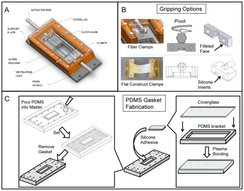
(A) Labeled chamber parts. Corresponding usages and sterilization options can be found in Table 1. (B) Gripping options inside testing chamber: a fiber clamping system with a pivoting head to maintain samples in parallel tension; a flat construct grip with spacing to accommodate constructs of varying thickness when compressed by silicone inserts. (C) PDMS Gasket fabrication: Two-part PDMS mixture is poured into a custom-designed master mold and allowed to cure. The negative part (gasket) is replicated as needed to match chamber needs. In parallel, coverglass is plasma-bonded to a spacer bracket (PDMS). The coverglass-spacer assembly is later glued into the gasket opening using silicone adhesive.
Imaging Access
Below the chamber housing, a liquid-tight seal is maintained by screwing the chamber housing into a gasket made of polydimethylsiloxane (PDMS), which also contains the inlaid coverglass for optical access. In order to fabricate the gasket assembly, a fabrication protocol was utilized, as shown in Figure 1c. Briefly, a gasket base and bracket (to match 50mm×20mm coverglass dimensions) were formed as separate parts from a 2-component PDMS mixture (GE RTV615, Momentive). Using a March™ CS1701F Reactive Ion Etcher, the bracket was then plasma-bonded to a piece of coverglass, which was then glued into the larger PDMS gasket using a silicone adhesive (GE RTV108, Momentive™). The coverglass (1.5 Borosilicate, 170μm thick, Fisher) allows optical penetration and non-obstructive imaging in situ. Use of coverglass that deviate from this intended thickness in conjunction with these standard objective designs will result in spherical aberration and a reduction in resolution and image intensity. The entire gasket assembly was designed as a consumable item, such that it could be readily replaced if the delicate coverglass was damaged during routine assembly, sterilization, or cleaning. The testing assembly, including chamber housing and gripping assembly and all adhesives selected were constructed out of materials which could undergo repeated steam autoclave cycles (see Table 1), including stainless steel, silicone, polycarbonate, and polyetherimide (Ultem™).
TABLE 1.
Parts used in the assembly of bioreactor chambers, their uses, and sterilization methods.
| Part | Material | Function | Sterilization Method |
|---|---|---|---|
| Chamber Housing | Ultem™ | Contain media, access vents | Steam |
| Chamber Base | Stainless Steel | Support chamber | Steam |
| PDMS Gasket | PDMS/Glass | Bonding coverglass, liquid seal | Steam |
| Testing Plate | Aluminum, annodized | Support testing assembly | Ethanol |
| Ventilation | n/a | Connection to Wharton™ filters | Steam |
| Actuator Rods | Stainless Steel | Connections to load cells, actuators | Steam |
| Vessel Lid | Polycarbonate | Maintain sterility, condenser access | Ethanol/Steam |
| Support Plate | Stainless Steel | Fix to testing platform | Steam |
| Clamps | Ultem™, Stainless Steel | Grip specimens, hold fixed for imaging | Steam |
Mechanical Data Acquisition and Control
When not being imaged, the bioreactor is fixed to the stretching platform as shown in Figure 2. The entire stretching platform, including the initial design capacity of 4 chambers, is designed to fit and operate within a standard laboratory incubator, which controls environmental conditions, such as CO2 and temperature (see Figure 3A). This platform can be replicated as needed for more high-throughput needs. Individual linear actuators (35000 Series, Size 12 Linear Actuator; HSI, Waterbury, CT) are controlled by a motor controller board (Peter Norberg Consulting, Inc. SS4D10USB) and National Instruments (NI, Austin, TX) LabVIEW™ software. Based on the actuator specifications and anticipated sample starting dimensions (from ~5–80mm in length), each sample could be stretched upwards of 40% nominal strain, well beyond the anticipated material failure regime of most biomaterials presently employed to replicate soft tissues. The 3500 model linear actuator has a microstep size of <0.1μm linear displacement which corresponds to <0.001% of the sample gage length for constructs used in this study. While in situ calibration studies were not feasible in the confined chamber environment, in controlled comparison studies on known non-biological materials, the stress-strain response corresponded well with data generated on an Instron™ 3366 universal load frame. Depending on the application and material, it is anticipated that a cycling frequency of 1 Hz may be achievable. Load transferred through the sample is recorded using a submersible tensile load cell (Honeywell, Model 31) interfaced with a National Instruments CompactDAQ™ chassis and NI 9219 4-channel universal C Series module. The submersible load cell has a 2.5N capacity, a range commensurate with most early-stage engineered tissue constructs undergoing small (elastic) deformation. A single LabVIEW™ software interface, including a graphical user interface, is used to provide commanded stretch profiles for each sample and record load cell data.
Figure 2. Data collection and control in the bioreactor.

The stretching modality is controlled by stepper motor board (N=4 constructs simultaneously in separate vessels). Data acquisition from load cells (Honeywell, Model 31) is performed by NI CompactDAQ™ chassis with an NI 4-channel universal C Series module. The imaging modality is used in conjunction with either a confocal microscopy or multiphoton microscopy technique, by selecting appropriate laser light sources and/or the use of confocal pinholes. Each individual vessel (shown with top removed) spans the sample across a 1.5 coverglass.
Figure 3. Photos of the bioreactor in regular usage.

(A) Constructs are housed in 4 vessels, as seen in the complete platform assembly (380 mm × 380 mm) that fits within a standard incubator. (B) The testing chamber fits on a stage platform between the condenser and objective of an inverted light or confocal microscope. The glass on the top of the chamber allows for brightfield illumination or to collect light in the forward scattering direction when illuminated from below.
General Imaging Techniques
A schematic of a typical inverted microscope, including laser sources and optics components, is shown in Figure 2B. Each chamber is readied for imaging by unfastening the chamber from the stretching platform and placing it between the objective and condenser for phase contrast or confocal microscopy (CM) (see Fig. 3B). During the current experiments, chambers were imaged using a Leica DMIRE2 microscope stage with TCS SP2 scanner (Wetzlar, Germany). Briefly, the portion of the vessel above the 1.5 coverglass is placed over the objective with extender installed (Leica). Appropriate excitation and emission filter settings were selected to optimize signals from Live/Dead staining used in validation, DiI staining used in the short-term culture study, and GFP-labeled cells in the long-term culture experiment, as described elsewhere24. Slices at 2 μm steps (z-direction, through the construct thickness) were frame averaged three times and collected as stacks, ranging from 200 – 700 μm total thickness depending on the construct type, geometry, and strength of signal. During imaging, static clamping helped to maintain sample height and alignment for samples that would otherwise have a tendency to float in media or leave the field of view due to minor agitation. All images in the present work were acquired using a 10×0.4 NA objective, resulting in image sizes of 1.5×1.5mm; however, 20X objectives have also successfully been employed to visualize greater cell-level details (data not shown). Leica Confocal Software (Wetzlar, Germany) was utilized to record images and optics settings used during each experiment.
Alternatively, Multi-Photon Microscopy (MPM) was employed as a noninvasive method to achieve increased depth of penetration as compared to CM. Second Harmonic Generation (SHG) images can be obtained as previously described7, using an excitation at 800 nm and a tunable Ti:sapphire laser (Mai-Tai, Spectra Physics) emitting 100 fs pulses at 80 MHz. The SHG signal is detected in the forward direction (through the inlaid glass slide on the top of the chamber) using a high transmittance, 20 nm bandpass filter centered at 400 nm designed for two-photon imaging measurements (Chroma, HQ400/20 m-2P). Simultaneously, TPEF emission (specific to silk scaffolds or fluorescently-labeled cells) were detected from a non-descanned PMT with a filter cube containing a 700-nm short pass filter (Chroma SPC700 bp) a dichroic mirror (Chroma 495dcxr), and emitter bandpass filter centered at 455 nm (Chroma 455bp70). Slices at 2.5 μm steps were utilized using MPM techniques for all studies.
Validation: 3D Porous Constructs
In order to validate that imaging accessibility was not compromised due to the construct positioning in the chamber, we prepared highly cellularized and collagen-rich constructs and compared reconstructed cell/scaffold images either clamped and imaged in situ, or removed from the chamber and placed in a commercially-available MatTek petri dish with 1.5um window built into the bottom (MatTek Corporation, Ashland MA). Additionally, we assessed the construct’s mechanical response in the bioreactor system as compared to an Instron™ 3366 testing instrument to validate the load cell’s accuracy. Cell-laden porous scaffolds were prepared as previously described20. Briefly, 700–800um pore-size aqueous-based porous silk-based sponges (n=3) were fabricated24, and isolated cervical fibroblasts were statically seeded prior to 6 weeks of spinner flask culture in Dulbecco’s modified Eagles’ medium (DMEM, Invitrogen), containing 1X Penicillin/Streptomycin/Fungizone (PSF) and 10% Fetal Bovine Serum (FBS). Constructs were then removed from spinner flask culture and loaded into the flat clamps (Figure 1) via a custom-designed clamping stage. An image of the constructs in the clamps and an SEM image of the porous architecture of the scaffold can be seen in Figure 4.
Figure 4. Validation of imaging and mechanics using porous sponge constructs.

A cell-laden porous sponge was assessed following 6 weeks of spinner flask culture and 3 days of bioreactor culture (shown upper left). A representative SEM image of an acellular scaffold porous is included as an inset. Samples were stained by live/dead reagents and imaged in situ inside the reactor vessel or separately in a MatTek petri dish via confocal optics. Calcein AM stained live cells green and the silk scaffold nonspecifically bound to ethidium homodimer-1 for a red stain. A cross-section is visualized (through the dotted midline of each channel) and section thickness recorded beside cross-section. 3D composite stacks were reconstructed with live/dead channel overlays and shown as isometric projections. Using multi-photon microscopy (MPM) samples were visualized for collagen content using second harmonic generation (SHG, false-colored orange) and scaffold/cells were identified using two-photon excitation fluorescence (TPEF, false-colored green). Pure collagen fiber SHG signal is shown as an inset to the SHG image to confirm specificity of this channel. Load cell data recorded during stretch treatment in the bioreactor was compared to that using a separate Instron™ system at the onset of stretch (0hr) and after 2 complete cycles (24hr). All front view optics images x-y overall dimensions 1.5mm × 1.5mm.
The clamped samples were screwed into the bioreactor rods, 12mL of serum-containing DMEM media added, and a three-day loading protocol was administered. Prior to the onset of cyclic loading, the sample was pulled until a 0.1N load was registered on the load cell and sample allowed to relax for 10 minutes. Following the tare loading procedure, the loading protocol consisted of a 10% strain (one load-unload cycle) at a rate of .0033s−1, followed by 2 minutes of rest, for a total of 3 minutes per cycle. This loading regime mimicked that of the female cervix undergoing intermittent contractions lasting 60 seconds, with a strain range (10%) that was the maximum elastic deformation allowable for the tissue engineered construct at full maturity20. This cyclic load was repeated 240 times for a total loading duration of 12 hours, at which point the sample was unloaded and allowed to relax for the remaining 12 hours until the next day of loading. This procedure was repeated 3 times, including taring each day, at which point the loading protocol was completed and samples analyzed.
Mechanical Analysis
Load cell data was obtained during periods of loading at a rate of 10Hz, and was logged throughout the 3 days of loading. Separately, samples were taken from spinner flask culture and were clamped using the flat clamps inside a Biopuls™ testing bath filled with 0.1M Phosphate Buffered Saline (PBS, Sigma) mounted to an Instron™ Model 3366 Testing frame. The sample was loaded as described above for 12 hrs, followed by an additional 12 hrs of loading at the same interval and frequency in order to recreate the same number of cycles as achieved over 2 days of sequential loading in the bioreactor. This was based on the concern that the construct would degrade or become moldy if left in an open container of PBS for more than 24hrs. Load data was normalized to cross-sectional area and converted to stress based on caliper measurements.
Confocal and MPM Imaging Validation
Following 3 days of loading, samples were then stained with a Live/Dead reagent and images recorded after 30 minutes. Samples were also removed from their clamps and imaged in a MatTek petri dish for comparison. In order to demonstrate that MPM imaging was likewise feasible inside the testing chamber, and thus that the emission signal could be collected unobstructed in the forward direction (through the inlaid glass at the top of the chamber), a construct was separately reserved after stretching (but not Live/Dead stained) and imaged using MPM parameters described above. The constructs have previously been assessed to contain 4.7% collagen overall (dry wt.) and are more protein-rich near the scaffold periphery than in the center of the construct as described elsewhere20.
To validate that the optical channel was in fact responding to a collagen signal and not purely background silk, we separately prepared pure collagen fibers with strong SHG signals. Briefly, individual, small-diameter collagen fibers were formed by extruding a collagen suspension derived from bovine tendon (Sigma-Aldrich) through microbore tubing (inner diameter 280 μm) into a fiber-formation phosphate buffer, as previously described 13,32. Following crosslinking and sterilization, fibers were clamped in fiber clamped and submerged in PBS prior, allowed to swell to equilibrium. Following this treatment, images were likewise captured and analyzed as described above using MPM techniques.
Imaging Analysis
Analysis of all imaging described above was performed with ImageJ (Ver. 1.43). In particular, projections were created in each available channel using a sequence of z-stacked images, and the “Volume Viewer” and “ImageJ 3D Viewer” plugins were used to create volume-rendered images and overlays. The bounds of discernable quality scans were used to define the imaging depth of penetration for each imaging technique.
Short-Term Study: MSC-laden Electrospun Mats
Electrospun scaffolds were prepared from a 12 wt% solution of poly(esterurethane urea) (PEUUR) in 1,1,1,3,3,3-hexaflouro-2-propanol (HFIP) as previously described6. Samples (n=4) were cut to 4.5 cm long by 1 cm wide and leached in ethanol then water to remove residual solvent. Samples were dried and then sterilized using an Anprolene Ethylene Oxide sterilizer (Andersen Products, Inc., Haw River, NC), aerated for 24 hours. The samples were coated with 5μg/mL fibronectin (MP Biomedicals, Solon OH) prior to cell seeding. Mouse-derived mesenchymal stem cells (MSC, C3H10T1/2 p15, ATCC), labeled with DiI, were seeded at 15,000 cells/cm2 on the prepared samples in the holding chamber. All culture on electrospun mats was performed using DMEM supplemented with 10% FBS, 2 mM L-glutamine, 1% PSF, and 50 μg/mL L-ascorbic acid. After 24 hours, the constructs were loaded into individual reactor chambers, with the cell-seeded surface closest to the coverglass, and allowed to proliferate for 48 hours prior to stretching. The constructs were preloaded to 0.05 N, then subjected to 4% grip-grip strain (one load-unload cycle) at a rate of 0.001s−1 for 30 minutes per day for a total of 3 days. As controls, additional constructs (n=4) were placed under the fixed-length preload alone (≤0.05N preload) or alternatively left to grow in static, free swelling conditions. Cell attachment on the scaffold was verified following transfer to the reactor and after the initial and final stretching cycles using confocal microscopy settings defined above. After imaging on the final day of the short-term study, electrospun constructs from all three groups (static, preload, cyclic stretch) were destroyed for DNA quantification. Following freezing at −80°C, constructs were digested in 0.5 mg/mL papain buffer (MP Biomedicals) for 20 hours at 65°C and DNA content was measured using the Quant-iT PicoGreen® kit according to manufacturer’s instructions using a fluorescent plate reader (SpectraMax M2, Molecular Devices, Sunnyvale CA).
Long-Term Study: Fibroblast-Laden Silk Fibers
Raw silk yarns (imported by Rudolph-Desco, Inc.) were extracted using an aqueous solution containing 0.02M Na2CO3 (Sigma-Aldrich) and 0.3% Ivory Soap detergent as previously described 2. Prior to extraction, yarns were plied to 4 ends and 4 of these bundles were lightly twisted to form a 16-fiber construct using a Calvani™ Fancy Jet model 6/SP Ring Twister (Milan, Italy). For cell culture studies, silk yarns were RGD-modified based on previously defined methods 10. Human foreskin fibroblasts (HFF-1, SCRC-1041, ATCC) were cultured in DMEM supplemented with 15% fetal bovine serum, and 1x PSF for all studies. To visually track the HFF-1 cells a lentivirus system was employed to provide a stably-expressed GFP-expressing line of HFF-1 as described elsewhere26,36. The efficiency of GFP transduction was evaluated through fluorescence microscopy and fluorescence-activated cell sorting (FACS) (BD, Franklin Lakes, NJ). Two RGD-modified silk fibers were clamped in the custom fiber clamps with pivoting heads. Samples were sterilized using ethylene oxide (Andersen Products, Inc., Haw River, NC), aerated for 24 hours, then rinsed thoroughly with phosphate buffered saline (PBS) prior to air drying in a laminar flow hood. The unseeded fibers were pre-cycled 15 times prior to cell seeding in sterile PBS to obtain a repeatable stress-strain response25. Next, the clamps were removed from the loading chambers and GFP HFF-1 cells were seeded onto the fibers in a custom-designed Teflon well using 2 inoculations of 5×10⁵ cells/mL, one to each side of the fiber bundle. The samples were then left to grow to confluence over 5 days inside the chamber. At day 5, a continuous triangle wave displacement profile was subsequently applied to the sample pair every day for 1 hour at a constant strain rate. The triangular wave had a ramp load-unload rate of 0.1%s−1 (a quasi-static loading rate to avoid viscous effects) with a 2.5% stretch amplitude. The stretch treatment was repeated every day up to and including day 14 (10 total days of stretch), followed by imaging at each day according to the methodology described above. Load cells data was collected at a 10Hz frequency, and was normalized to stress by cross-sectional area measurement, assuming an individual filament was 5μm circular diameter, which was used to multiply by the counted number of fibers in each construct. Unstretched (cell-seeded) static controls were compared to the stretched constructs. The strain range and duration were selected to mimic the stretching conditions for the human ACL experienced during rehabilitation following graft surgery 19, as has been explored in other functional tissue engineering studies 31,37. Histology was used to confirm that at the terminal time point (14 days) the constructs were composed of cells surrounding the fibers as depicted by the confocal images. Briefly, 2-mm end sections of fibers harvested for mechanical tests were fixed and paraffin embedded. 5-micron sections were cut from each block and stained with hemotoxylin and eosin (H&E).
RESULTS
Validation and Defining Limitations: 3D Porous Constructs
In order to delineate the potential for multiple-channel (i.e. cellular vs. biomaterial) visualization and define limitations of imaging depth of penetration, we employed fibroblast-laden porous 3D silk sponge scaffolds. For these constructs, noninvasive imaging was conducted after 3 days of cycling inside the bioreactor and subsequent exposure to a Live/Dead assay. The ethidium homodimer-1 fluorescent dye adsorbed nonspecifically to the scaffold surface and allowed for a strong label while calcein AM stained live cells green; however, both were only visible as a thin rim by cross-section. Constructs imaged while being clamped inside the bioreactor were directly compared to the same constructs imaged inside a MatTEK culture plate (Figure 4). While images presented here indicated 248um penetration depth before loss of signal in the case of the MatTeK dish vs. 162um in the case of the in situ imaging of the bioreactor, we found this varied between samples and was dependent on the surface topography rather than intrinsic differences between setups. In general, there were no discernable resolution differences between the two systems, as “live” cells were easily identified in each system and overlays across the scaffold allowed for localization of cell colonies. Unlabeled cell-laden sponges were also imaged using MPM in the bioreactor. The TPEF signal from the silk scaffold (unlabeled) was visualized much deeper beyond the sample’s surface due to the improved spatial resolution of the MPM approach over confocal approaches. Likewise, collagen was seen deposited up to ~200um deep into pores but localized towards the surface of the samples consistent with histological findings previously described20. As confirmation, pure collagen fibers revealed a strong SHG signal with lateral dimensions that could be verified using phase contrast techniques (data not shown).
Load cell data was collected at the first cycle of the first day of loading as well as the first cycle of the second day of loading. Instron™ test data of a separate sample was used for comparison purposes. The two data sets compared very well – in particular, both systems were able to capture the nonlinear behavior of the stress/strain response. In general, bioreactor measurements appeared to underestimate Instron data; however, the inter-sample variability likely contributed to this discrepancy.
Short-Term Culture Study
Having proven that cell distribution could be observed in 3D cultures, we next investigated whether cell proliferation and morphology could be assessed over time as a means of simulating early-stage maturation of cell-laden tissue engineering constructs. For this, elastomeric electrospun nanofibrous scaffolds were employed because of their flat geometry and potential application for a growing community of researchers27. Cell attachment onto PEUUR electrospun scaffolds was verified prior to initiation of cyclic stretch using the confocal imaging modality of the bioreactor to visualize cell membranes impregnated with a non-permanent tracer dye (DiI) (Figure 5a). Cells were then visualized after mechanical stretch treatments to assess total cellularity and morphology over time. As shown in Figure 5b, confocal images suggest that cell density decreased immediately after the initial day’s 30-minute stretch regime was complete, as cells not securely adhered to the electrospun fibers likely detached. DiI-stained cells were imaged after three days of daily mechanical stimulation, confirming the presence of a dense population of cells on the scaffold (Figure 5c). The elongation and alignment of these cells appeared to coincide with the prevailing fiber direction; however, it was difficult to assess changes in morphological features as the semi-permanent tracker dye likely degraded or dissociated from the intracellular space over the three-day experiment. As an extension of these preliminary studies, cell number was quantified on electrospun constructs under static, preloaded or cyclic mechanical stretch. Cell number was similar in all groups, with a slight but not statistically significant increase in the cyclically stretched group (Figure 5d).
Figure 5. Results from short-term study.

MSCs were visualized on electrospun fiber mats prior to cyclic stretch (a), after one 30-minute stretching treatment (b) and after three days stretching treatment (c) using confocal microscopy (DiI stain, red). After three days of cyclic stretching, cell number was measured on constructs undergoing static, preloaded or cyclic mechanical stress (d). Scale bars = 300 μm
Long-Term Culture Study
We assessed the long-term bioreactor utility with a culture of cell-seeded silk protein fibers under uniaxial stretch, as has been previously investigated without the access of in situ optical approaches 4,11. Neonatal Human Foreskin Fibroblasts (HFF-1) cells were selected as the cell line, as they are known to rapidly remodel the extracellular matrix (ECM)1, and also have been shown to be more mechano-sensitive than aged cells of the same lineage5. Labeling via GFP enhanced the ability to monitor the cellularity of the construct over time while simultaneously the intrinsic fluorescence signal from the silk fibers could be overlaid to assess cellular distribution (see Figure 6). Fibers seeded with cells and left to grow in expansion media reached near confluency by 4 days; however, subsequent loading on day 5 caused a significant initial loss of cells as shown by the diminished green label immediately post-stretching. This observation is similar to the results of the short-term study using MSCs. However, with time, a sheath of cells was seen proliferating on the surface of the construct despite continued daily stretching. After 6 days of active loading, the scaffold was covered with a cell population that appeared indistinguishable compared to the unloaded control condition at day 14.
Figure 6. Results from long-term study.

Green-fluorescent protein (GFP) transfected dermal fibroblasts were statically seeded on silk fibers and grown to near confluency over 5 days prior to daily loading, which was applied every day thereafter until day 14. Confocal scans were taken daily of GFP-labeled cells (green) overlaid on silk fibers (red). Data shown for day 4, prior to stretch, and days 5, 11, and 14 following stretch. Images are shown as an average projection through a z-stack of 10μm sections (ranging from 300–450μm total depth) or below as an isometric 3D rendering of the same overlaid stacks. Live/dead staining for day 1 after seeding as comparison to non-labeled techniques. Scale bar = 300μm for projections and isometric views. For comparison, H&E staining shown for the terminal time point (14 days) in stretched (top) or static (bottom) conditions, scale bar = 100 μm. Black arrows point to silk fibers, white arrows point to cells. Mechanical test data (Stress vs. Stretch λ) corresponding to the 30th loading curve of the cyclic stretch condition at each time point is shown.
Load cell data was captured synchronously on the experimental platform for every load-unload cycle (60 total each day). Load cell data was collected daily at a rate of 10 Hz and converted to stress by assuming the fiber bundle had a nominal cross section of 0.0051 mm2, which was confirmed by the histological sections. Load cell data for 3 days is shown at the bottom of Figure 6. The loading response did not significantly change with time, although a slight softening effect was observed.
DISCUSSION
Online non-invasive monitoring of tissue engineered materials has been described22. Our aim was to design a new bioreactor system that would be versatile to accommodate various biomaterial geometries, higher throughput, more diverse modes of imaging, and the ability to test a statistically-relevant number of samples simultaneously. Importantly, optical access through the inverted optics in the design allows for both epiflourescene (backwards reflected direction) and forward direction through the glass chamber top and microscope condenser (TPEF, SHG). Further, the applied loading protocols and mechanical data collection (via submersible load cells) are combined to a single platform inside the incubator environment, allowing routine stretching data to be collected in situ, rather than requiring additional probing of mechanical properties outside the chamber. The design is modular and can be easily expanded to 10’s of samples running simultaneously. The system is also adaptable, allowing the ability to clamp and image a wide array of biomaterial geometries, from fiber to film to porous scaffold. This flexible design platform and software versatility will allow future users to both prescribe unique independent loading conditions for multiple samples in one experimental run, and better control loading conditions given the compartmentalized design. For example, if samples are a different length, strain-based rates and displacements can be accurately applied for individual chambers. Finally, the sample chambers are easy to install and remove for intermittent access and are subjected to unique fluid environments, avoiding potential contamination or cross-talk issues.
Several other testing systems are available commercially, including the Tissue Train culture system by Flexcell®, the LigaGen™ Bioreactor by Tissue Growth Technologies, and the ElectroForce® BioDynamic® Test Instruments by Bose EnduraTEC®. However, none of these systems currently allow for confocal imaging in combination with the diverse modes and flexibility of the current system. Several design features are necessary in order to overcome challenges introduced by incorporating optical access, including compact gripping mechanisms, a new method to securely incorporate a 1.5 coverglass, as well as overall chamber dimensions. Inverted microscopy was a preferable access approach over upright microscopy techniques so that the overall thickness of the construct would not be restricted. The current platform design provides more high-throughput capabilities as well: n=4 testing platforms can be simultaneously and independently stretched while load cell data is recorded; and many other chambers (16 are currently used) can be cultured statically simultaneously and await stretching later in the same day or left as static controls. These additional chambers can be switched out to other stretch platforms intermittently allowing for scale-up of experiments.
We showed that both confocal and MPM techniques could be used in the chamber, and that access to the samples was not limited based on these alternative means of acquiring emission profiles (in forward vs. backward directions). In fact, the thickness of vertical stacks of confocal images taken of cell-laden silk fibers reached upwards of 450μm, which suggests that the working distance of a 10X objective was not the limiting factor. In general, the penetration depth in confocal microscopy is limited by absorption of excitation energy throughout the beam path, and by specimen scattering of both the excitation and emission photons. This phenomenon resulted in resolution being mostly limited to the first 100–200μm of the porous silk constructs and to the outer periphery of the bundles of GFP cell-laden silk fiber constructs visualized using the confocal approach. Alternatively, multi-photon excitation (specifically two-photon) provides three-dimensional optical sectioning without absorption above and below the plane of focus. Consequently, the technique offers increased depth penetration as compared to confocal microscopy (~2–3x greater), and can be less phototoxic to live specimens. For this reason, SHG and TPEF signals used in validation studies constituted the entire cross-section of the image stacks of porous scaffolds despite their dense cell and ECM-rich structure that was likely to scatter incident light. In future studies, cell labeling techniques can be combined with MPM techniques to improve colocalization of distinct optical species.
The endogenous signatures of each material-cell-ECM system will likely be different depending on the application, but we have demonstrated that all three features can be probed simultaneously without the need to sacrifice samples mid-experiment. This information could be critical in a number of practical scenarios: i) deciding the appropriate time to apply mechanical stretch based on cell layer confluence, ii) immediately screening the effects of varied loading scenarios on cell retention, or iii) understanding the effect of load-induced scaffold changes (such as fiber alignment or plastic deformation) on cell colonies. These improvements should extend the practical window of in vitro screening experiments and allow for more rapid turnover of materials between experiments to accelerate research progress.
We did not observe any significant change in silk fiber mechanical properties over the course of our 2-week screening study. Therefore, in a follow-on study we performed a series of experiments to define the enzymatic susceptibility of silk fibers when actively loaded, including a computational and microstructural model to account for the observed changes in stress-strain response of silk fibers over prolonged culture periods25. In general, more quantitative comparisons of construct mechanics and biological changes will be addressed in future studies. Currently, we do not have the ability to track construct local strain patterns or perform optical strain on-line and in real-time because the system is housed in a confined incubator at elevated temperatures. However, a high resolution camera could be mounted above the coverglass during stretch to record local displacement in future studies.
In conclusion, the newly designed bioreactor system is a versatile and robust experimental system that should significantly extend the scope of ongoing tissue culture experiments incorporating mechanical stretch or routine stimulation. The confluence of mechanics and imaging in one system provides a new tool for the biomaterials and tissue engineering community to permit nondestructive assessments of biomaterials, cells and matrices in a more dynamic and useful fashion. The demonstration of utility of the system for fiber- and sponge-based biomaterial scaffolds suggests a broad range of utility in tissue engineering and biomaterial remodeling studies.
Acknowledgments
We thank those at Tufts University for their technical assistance: Amy Thurber for support with cell culture experiments; Minchul Shin, Kosta Tsioris, and Rob White for their help in gasket fabrication techniques; Scott MacCorkle, Dennis Dupuis, and Larry McMaster in the Dept. of Physics machine shop. Electrospinning of scaffolds and subsequent DNA analysis was performed in the laboratory of Aaron Goldstein at Virginia Tech. Funding supplied by the US National Institutes of Health (NIH) (P41 EB002520, R25 GM073177-01, and F31 AR055872).
References
- 1.Abraham LC, Dice JF, Lee K, Kaplan DL. Phagocytosis and remodeling of collagen matrices. Exp Cell Res. 2007;313:1045–1055. doi: 10.1016/j.yexcr.2006.12.019. [DOI] [PMC free article] [PubMed] [Google Scholar]
- 2.Altman GH, Horan RL, Lu HH, Moreau J, Martin I, Richmond JC, Kaplan DL. Silk matrix for tissue engineered anterior cruciate ligaments. Biomaterials. 2002;23:4131–4141. doi: 10.1016/s0142-9612(02)00156-4. [DOI] [PubMed] [Google Scholar]
- 3.Altman GH, Horan RL, Martin I, Farhadi J, Stark PR, Volloch V, Richmond JC, Vunjak-Novakovic G, Kaplan DL. Cell differentiation by mechanical stress. Faseb J. 2002;16:270–272. doi: 10.1096/fj.01-0656fje. [DOI] [PubMed] [Google Scholar]
- 4.Altman GH, Lu HH, Horan RL, Calabro T, Ryder D, Kaplan DL, Stark P, Martin I, Richmond JC, Vunjak-Novakovic G. Advanced bioreactor with controlled application of multi-dimensional strain for tissue engineering. J Biomech Eng. 2002;124:742–749. doi: 10.1115/1.1519280. [DOI] [PubMed] [Google Scholar]
- 5.Balestrini JL, Billiar KL. Equibiaxial cyclic stretch stimulates fibroblasts to rapidly remodel fibrin. J Biomech. 2006;39:2983–2990. doi: 10.1016/j.jbiomech.2005.10.025. [DOI] [PubMed] [Google Scholar]
- 6.Bashur CA, Shaffer RD, Dahlgren LA, Guelcher SA, Goldstein AS. Effect of fiber diameter and alignment of electrospun polyurethane meshes on mesenchymal progenitor cells. Tissue Eng Part A. 2009;15:2435–2445. doi: 10.1089/ten.tea.2008.0295. [DOI] [PubMed] [Google Scholar]
- 7.Bayan C, Levitt JM, Miller E, Kaplan D, Georgakoudi I. Fully automated, quantitative, noninvasive assessment of collagen fiber content and organization in thick collagen gels. J App Phys. 2009;105 doi: 10.1063/1.3116626. [DOI] [PMC free article] [PubMed] [Google Scholar]
- 8.Butler DL, Juncosa-Melvin N, Boivin GP, Galloway MT, Shearn JT, Gooch C, Awad H. Functional tissue engineering for tendon repair: A multidisciplinary strategy using mesenchymal stem cells, bioscaffolds, and mechanical stimulation. J Orthop Res. 2008;26:1–9. doi: 10.1002/jor.20456. [DOI] [PubMed] [Google Scholar]
- 9.Caruso AB, Dunn MG. Functional evaluation of collagen fiber scaffolds for ACL reconstruction: cyclic loading in proteolytic enzyme solutions. J Biomed Mater Res A. 2004;69:164–171. doi: 10.1002/jbm.a.20136. [DOI] [PubMed] [Google Scholar]
- 10.Chen J, Altman GH, Karageorgiou V, Horan R, Collette A, Volloch V, Colabro T, Kaplan DL. Human bone marrow stromal cell and ligament fibroblast responses on RGD-modified silk fibers. J Biomed Mater Res A. 2003;67:559–570. doi: 10.1002/jbm.a.10120. [DOI] [PubMed] [Google Scholar]
- 11.Chen J, Horan RL, Bramono D, Moreau JE, Wang Y, Geuss LR, Collette AL, Volloch V, Altman GH. Monitoring mesenchymal stromal cell developmental stage to apply on-time mechanical stimulation for ligament tissue engineering. Tissue Eng. 2006;12:3085–3095. doi: 10.1089/ten.2006.12.3085. [DOI] [PubMed] [Google Scholar]
- 12.Discher DE, Janmey P, Wang YL. Tissue cells feel and respond to the stiffness of their substrate. Science. 2005;310:1139–1143. doi: 10.1126/science.1116995. [DOI] [PubMed] [Google Scholar]
- 13.Gentleman E, Lay AN, Dickerson DA, Nauman EA, Livesay GA, Dee KC. Mechanical characterization of collagen fibers and scaffolds for tissue engineering. Biomaterials. 2003;24:3805–3813. doi: 10.1016/s0142-9612(03)00206-0. [DOI] [PubMed] [Google Scholar]
- 14.Georgakoudi I, Rice WL, Hronik-Tupaj M, Kaplan DL. Optical spectroscopy and imaging for the noninvasive evaluation of engineered tissues. Tissue engineering. 2008;14:321–340. doi: 10.1089/ten.teb.2008.0248. [DOI] [PMC free article] [PubMed] [Google Scholar]
- 15.Gilbert TW, Stewart-Akers AM, Sydeski J, Nguyen TD, Badylak SF, Woo SL. Gene expression by fibroblasts seeded on small intestinal submucosa and subjected to cyclic stretching. Tissue Eng. 2007;13:1313–1323. doi: 10.1089/ten.2006.0318. [DOI] [PubMed] [Google Scholar]
- 16.Gupta S, Hunter M, Cebe P, Levitt JM, Kaplan DL, Georgakoudi I. Non-invasive optical characterization of biomaterial mineralization. Biomaterials. 2008;29:2359–2369. doi: 10.1016/j.biomaterials.2008.01.034. [DOI] [PMC free article] [PubMed] [Google Scholar]
- 17.Gupta S, Hunter M, Kaplan D, Georgakoudi I. Optical characterization of the nanoscale organization of mineral deposits on silk films. Appl Opt. 2009;48:D45–51. doi: 10.1364/ao.48.000d45. [DOI] [PubMed] [Google Scholar]
- 18.Hagenmuller H, Hitz M, Merkle HP, Meinel L, Muller R. Design and validation of a novel bioreactor principle to combine online micro-computed tomography monitoring and mechanical loading in bone tissue engineering. Rev Sci Instrum. 2010;81:014303. doi: 10.1063/1.3284787. [DOI] [PubMed] [Google Scholar]
- 19.Heijne A, Fleming BC, Renstrom PA, Peura GD, Beynnon BD, Werner S. Strain on the anterior cruciate ligament during closed kinetic chain exercises. Med Sci Sports Exerc. 2004;36:935–941. doi: 10.1249/01.mss.0000128185.55587.a3. [DOI] [PubMed] [Google Scholar]
- 20.House M, Sanchez CC, Rice WL, Socrate S, Kaplan DL. Cervical tissue engineering using silk scaffolds and human cervical cells. Tissue Eng Part A. 2010;16:2101–2112. doi: 10.1089/ten.tea.2009.0457. [DOI] [PMC free article] [PubMed] [Google Scholar]
- 21.Hu JJ, Humphrey JD, Yeh AT. Characterization of engineered tissue development under biaxial stretch using nonlinear optical microscopy. Tissue Eng Part A. 2009;15:1553–1564. doi: 10.1089/ten.tea.2008.0287. [DOI] [PMC free article] [PubMed] [Google Scholar]
- 22.Humphrey JD, Wells PB, Baek S, Hu JJ, McLeroy K, Yeh AT. A theoretically-motivated biaxial tissue culture system with intravital microscopy. Biomech Model Mechanobiol. 2008;7:323–334. doi: 10.1007/s10237-007-0099-5. [DOI] [PubMed] [Google Scholar]
- 23.Jin HJ, Fridrikh SV, Rutledge GC, Kaplan DL. Electrospinning Bombyx mori silk with poly(ethylene oxide) Biomacromolecules. 2002;3:1233–1239. doi: 10.1021/bm025581u. [DOI] [PubMed] [Google Scholar]
- 24.Kim HJ, Kim UJ, Leisk GG, Bayan C, Georgakoudi I, Kaplan DL. Bone regeneration on macroporous aqueous-derived silk 3-D scaffolds. Macromolecular bioscience. 2007;7:643–655. doi: 10.1002/mabi.200700030. [DOI] [PubMed] [Google Scholar]
- 25.Kluge JA, Thurber A, Leisk GG, Kaplan DL, Dorfmann AL. A model for the stretch-mediated enzymatic degradation of silk fibers. J Mech Behav Biomed Mater. 2010;3:538–547. doi: 10.1016/j.jmbbm.2010.06.008. [DOI] [PMC free article] [PubMed] [Google Scholar]
- 26.Lovett M, Cannizzaro C, Daheron L, Messmer B, Vunjak-Novakovic G, Kaplan DL. Silk fibroin microtubes for blood vessel engineering. Biomaterials. 2007;28:5271–5279. doi: 10.1016/j.biomaterials.2007.08.008. [DOI] [PMC free article] [PubMed] [Google Scholar]
- 27.Mauck RL, Baker BM, Nerurkar NL, Burdick JA, Li WJ, Tuan RS, Elliott DM. Engineering on the Straight and Narrow: the Mechanics of Nanofibrous Assemblies for Fiber-Reinforced Tissue Regeneration. Tissue engineering. 2009;15:171–193. doi: 10.1089/ten.teb.2008.0652. [DOI] [PMC free article] [PubMed] [Google Scholar]
- 28.Mauck RL, Soltz MA, Wang CC, Wong DD, Chao PH, Valhmu WB, Hung CT, Ateshian GA. Functional tissue engineering of articular cartilage through dynamic loading of chondrocyte-seeded agarose gels. J Biomech Eng. 2000;122:252–260. doi: 10.1115/1.429656. [DOI] [PubMed] [Google Scholar]
- 29.Meinel L, Hofmann S, Karageorgiou V, Kirker-Head C, McCool J, Gronowicz G, Zichner L, Langer R, Vunjak-Novakovic G, Kaplan DL. The inflammatory responses to silk films in vitro and in vivo. Biomaterials. 2005;26:147–155. doi: 10.1016/j.biomaterials.2004.02.047. [DOI] [PubMed] [Google Scholar]
- 30.Niklason LE, Yeh AT, Calle EA, Bai Y, Valentin A, Humphrey JD. Enabling tools for engineering collagenous tissues integrating bioreactors, intravital imaging, and biomechanical modeling. Proc Natl Acad Sci USA. 2010;107:3335–3339. doi: 10.1073/pnas.0907813106. [DOI] [PMC free article] [PubMed] [Google Scholar]
- 31.Nirmalanandhan VS, Juncosa-Melvin N, Shearn JT, Boivin GP, Galloway MT, Gooch C, Bradica G, Butler DL. Combined effects of scaffold stiffening and mechanical preconditioning cycles on construct biomechanics, gene expression, and tendon repair biomechanics. Tissue Eng Part A. 2009;15:2103–2111. doi: 10.1089/ten.tea.2008.0335. [DOI] [PMC free article] [PubMed] [Google Scholar]
- 32.Pins GD, Christiansen DL, Patel R, Silver FH. Self-assembly of collagen fibers. Influence of fibrillar alignment and decorin on mechanical properties. Biophys J. 1997;73:2164–2172. doi: 10.1016/S0006-3495(97)78247-X. [DOI] [PMC free article] [PubMed] [Google Scholar]
- 33.Pully VV, Lenferink A, van Manen HJ, Subramaniam V, van Blitterswijk CA, Otto C. Microbioreactors for Raman microscopy of stromal cell differentiation. Anal Chem. 2010;82:1844–1850. doi: 10.1021/ac902515c. [DOI] [PubMed] [Google Scholar]
- 34.Rice WL, Firdous S, Gupta S, Hunter M, Foo CW, Wang Y, Kim HJ, Kaplan DL, Georgakoudi I. Non-invasive characterization of structure and morphology of silk fibroin biomaterials using non-linear microscopy. Biomaterials. 2008;29:2015–2024. doi: 10.1016/j.biomaterials.2007.12.049. [DOI] [PMC free article] [PubMed] [Google Scholar]
- 35.Rice WL, Kaplan DL, Georgakoudi I. Two-photon microscopy for non-invasive, quantitative monitoring of stem cell differentiation. PLoS One. 5:e10075. doi: 10.1371/journal.pone.0010075. [DOI] [PMC free article] [PubMed] [Google Scholar]
- 36.Rubinson DA, Dillon CP, Kwiatkowski AV, Sievers C, Yang L, Kopinja J, Rooney DL, Zhang M, Ihrig MM, McManus MT, Gertler FB, Scott ML, Van Parijs L. A lentivirus-based system to functionally silence genes in primary mammalian cells, stem cells and transgenic mice by RNA interference. Nat Genet. 2003;33:401–406. doi: 10.1038/ng1117. [DOI] [PubMed] [Google Scholar]
- 37.Shearn JT, Juncosa-Melvin N, Boivin GP, Galloway MT, Goodwin W, Gooch C, Dunn MG, Butler DL. Mechanical stimulation of tendon tissue engineered constructs: effects on construct stiffness, repair biomechanics, and their correlation. J Biomech Eng. 2007;129:848–854. doi: 10.1115/1.2800769. [DOI] [PubMed] [Google Scholar]
- 38.Webb AR, Macrie BD, Ray AS, Russo JE, Siegel AM, Glucksberg MR, Ameer GA. In vitro characterization of a compliant biodegradable scaffold with a novel bioreactor system. Ann Biomed Eng. 2007;35:1357–1367. doi: 10.1007/s10439-007-9304-z. [DOI] [PubMed] [Google Scholar]