Abstract
The voltage-sensor domain (VSD) is a modular 4-helix bundle component that confers voltage sensitivity to voltage-gated cation channels in biological membranes. Despite extensive biophysical studies and the recent availability of x-ray crystal structures for a few voltage-gated potassium (Kv-) channels and a voltage-gate sodium (Nav-) channel, a complete understanding of the cooperative mechanism of electromechanical coupling, interconverting the closed-to-open states (i.e. non-conducting to cation conducting) remains undetermined. Moreover, the function of these domains is highly dependent on the physical-chemical properties of the surrounding lipid membrane environment. The basis for this work was provided by a recent structural study of the VSD from a prokaryotic Kv-channel vectorially-oriented within a single phospholipid (POPC; 1-palmitoyl-2-oleoyl-sn-glycero-3-phosphocholine) membrane investigated by x-ray interferometry at the solid/moist He (or solid/vapor) and solid/liquid interfaces thus achieving partial to full hydration, respectively (Gupta et. al. Phys. Rev E. 2011, 84). Here, we utilize neutron interferometry to characterize this system in substantially greater structural detail at the sub-molecular level, due to its inherent advantages arising from solvent contrast variation coupled with the deuteration of selected sub-molecular membrane components, especially important for the membrane at the solid/liquid interface. We demonstrate the unique vectorial orientation of the VSD and the retention of its molecular conformation manifest in the asymmetric profile structure of the protein within the profile structure of this single bilayer membrane system. We definitively characterize the asymmetric phospholipid bilayer solvating the lateral surfaces of the VSD protein within the membrane. The profile structures of both the VSD protein and phospholipid bilayer depend upon the hydration state of the membrane. We also determine the distribution of water and exchangeable hydrogen throughout the profile structure of both the VSD itself and the VSD:POPC membrane. These two experimentally-determined water and exchangeable hydrogen distribution profiles are in good agreement with molecular dynamics simulations of the VSD protein vectorially-oriented within a fully hydrated POPC bilayer membrane, supporting the existence of the VSD’s water pore. This approach was extended to the full-length Kv-channel (KvAP) at solid/liquid interface, providing the separate profile structures of the KvAP protein and the POPC bilayer within the reconstituted KvAP:POPC membrane.
1. INTRODUCTION
Voltage-gated potassium (Kv) and sodium (Nav) channels play a central role in neurological signal transmission, notably the generation and propagation of action potentials.1,2,3 They are also responsible for several “channelopathy” diseases4,5,6,7,8 and are potential sites for anesthetic action.9,10 Kv-channels are prototypical, in that high-resolution X-ray crystal structures of the presumed open-state of a few Kv-channels have recently been determined.11,12,13,14,15 The transmembrane domain of the channel is comprised of four identical subunits arranged about a 4-fold axis normal to the membrane plane, each possessing six transmembrane alpha-helices S1-S6. Helices S5 and S6 from each subunit combine to form the pore domain (PD) in the homo-tetramer that is conserved from archaebacteria to mammals. The PD opens in response to depolarizing transmembrane electrochemical potentials to permit passive ion transport giving rise to “ionic” currents. Helices S1-S4 in each subunit comprise a voltage sensor domain (VSD), including four charged Arg (R) residues in S4 shown to be primarily responsible for voltage-sensing. The N-terminus and C-terminus of each subunit are on the intracellular side of the cell membrane, as is the loop connecting the VSD and PD. The VSD has a “modular” aspect in that it can be interchanged between different Kv-channels,16 and it can impart voltage-sensitivity to an otherwise passive K+-channel possessing only the analogous PD.13
Transmembrane voltage sensing requires an electromechanical coupling between the VSD’s and PD, the mechanism of which remains unresolved, despite intense investigation worldwide,17,18,19,20,21,22 for several reasons. First, the resting, closed state of the Kv-channel occurs naturally only at a transmembrane potential of about −90 to −100 mV, not present with the available 3-D crystal structures. Second, the protein undergoes sequential conformational changes as it opens from the closed state, thereby requiring multiple structures to fully describe the functional system.11,12,20 Initially, the VSD of each subunit must be activated involving two intermediates and charged residue movements along the membrane profile result in “gating” currents, but without ion conduction. When all four VSDs are activated, the channel is poised to open, but not yet conducting ions. This fully activated state then undergoes a rapid cooperative transformation to the open, ion conducting state of the PD. Third, depolarizing transmembrane potentials are required to trigger these structural changes, and this is not feasible with the available 3-D crystal structures. Fourth, there is growing evidence that interactions between the protein, particularly the VSD, and the phospholipid in the membrane affect the protein function. For example, the function is modulated by the micro-environment provided by the host membrane including its fluidity, thickness, and composition.23,24,25,26 Incorporation of a Kv-channel into a lipid bilayer lacking phosphate in its polar headgroup such as DOTAP (2,3-dioleoyloxy-1-propyl)trimethyl-ammonium methyl sulfate) renders the channel insensitive to the transmembrane potential, with the sensitivity restored upon exchanging the DOTAP for phospholipid.27 Therefore, a full understanding of the mechanism likely requires the investigation of the structure of these channels in a host phospholipid membrane under applied transmembrane potentials, making the development of both novel membrane reconstitution approaches and appropriate structural techniques indispensable. This prompted us to focus initially on the structure of the isolated VSD itself, as well as the full-length KvAP channel, incorporated with a uni-directional vectorial orientation within a single phospholipid bilayer membrane environment. We note that investigation of the VSD itself gains additional importance arising from its homology with voltage-gated hydrogen channels such as Hv1, whose biological significance has been increasing steadily since the cloning of the Hv1 gene in 2006. The prokaryotic KvAP (Kv-channel from thermophilic archaebacteria Aeropyrum pernix) is structurally simpler possessing only the transmembrane domain central to electromechanical coupling which is highly similar to its eukaryotic counterparts, but lacking their large cytoplasmic domain.
In a recent publication,28 we described two independent approaches to form a vectorially-oriented monolayer of the detergent-solubilized expressed protein (VSD or full-length KvAP) tethered to the surface of inorganic (multilayer) substrates. The first was designated as Directed-Assembly (DA) and the second was designated as Self-Assembly (SA). Only the SA approach was employed for the KvAP protein. The single monolayer of the vectorially-oriented detergent-solubilized protein was subsequently exchanged against a POPC/detergent mixture in the presence of a solid-phase possessing an affinity for the detergent, intended to reconstitute a POPC bilayer environment for the tethered protein. We then characterized the profile structures of the single monolayers of the detergent-solubilized expressed proteins and the so-reconstituted protein:phospholipid membranes via X-ray interferometry, namely X-ray reflectivity enhanced by interference with a multilayer reference structure,29,30 with the membrane at either the solid/moist He or solid/liquid interface. The latter interface required high-energy X-rays to penetrate the aqueous liquid membrane environment. We note that the “physics” underlying the interferometric approach for both X-ray and neutron reflectivity has been thoroughly described in prior work.30,41 Here, “profile structure” refers to a projection of the 3-D structure of the monolayer or membrane parallel to the plane of the monolayer/membrane onto the normal to that plane, thereby averaging over their respective in-plane structures. Comparison of the resulting asymmetric profile structures for the detergent-solubilized proteins with those calculated from their respective x-ray crystal structures verified the intended vectorial orientation of each protein and indicated retention of the protein’s folded 3-D tertiary structure upon completion of bilayer membrane reconstitution. Difference profile structures for the VSD:POPC membrane versus the VSD:detergent monolayer suggested a successful reconstitution of a POPC bilayer environment for the VSD protein.
Neutron reflectivity, also enhanced via interferometry, has some particular advantages for the investigation of such structures. These arise from the fact that while X-rays are scattered by atomic electrons thereby varying with atomic number, neutrons are scattered by atomic nuclei with most exhibiting potential scattering of comparable amplitude. However, a few isotopes of a few elements exhibit resonance scattering, which changes both the amplitude and phase of the scattered neutrons. Importantly for soft matter, deuterium (2H or D) exhibits potential scattering like most other atomic nuclei of comparable positive amplitude (bD= +6.67×10⁻⁵ Å), while hydrogen (1H) exhibits resonance scattering of negative amplitude (bH= −3.74×10⁻⁵ Å), by convention the change of sign arising from a change in the relative phase of the scattered neutron for potential versus resonance scattering. Likewise, for D2O and H2O–based solvents the scattering length densities are positive (+6.36 × 10⁻⁶ Å−2) and negative (−0.56 × 10⁻⁶ Å−2), respectively. As a result, the neutron scattering contrast between a structure of interest, a membrane, and its solvation environment, an aqueous medium, can be manipulated by varying either the deuterium/hydrogen ratio of the membrane components or that of the aqueous medium (via the D2O/H2O ratio), the latter referred to as “solvent contrast variation”. When these two average contrasts are matched, neutron scattering from the structure of interest is either dramatically minimized or vanishes completely. Coupling these approaches allows the investigator to suppress the contrast for a selected membrane component while enhancing that of another, e.g. for the lipid versus the protein or for selected sub-molecular portions of either. Such isotopic substitution is generally nearly isomorphous for biological structures, thereby allowing the visualization of selected membrane components, or sub-molecular portions thereof, by comparison of the selectively deuterated structure with that fully hydrogenated via a difference structure or profile structure. The same approach is more problematic for the case of non-resonance X-ray scattering because the only way to change the scattering contrast at the atomic level is to change the atom (i.e. its atomic number), which need not be isomorphous, depending on its role in stabilizing the structure of interest, thereby rendering the analogous difference structure irrelevant for this purpose.
In this work, we utilized neutron reflectivity, enhanced by interferometry, to characterize the VSD:detergent monolayer and reconstituted VSD:phospholipid membrane systems in substantially greater structural detail at the sub-molecular level, due to its inherent advantages arising from solvent contrast variation coupled with the deuteration of selected sub-molecular membrane components as described above. This neutron scattering approach is especially effective for the monolayer or membrane at the solid/liquid interface, since for the analogous case of X-ray scattering, the relevant electron density contrast for the monolayer or membrane is more comparable to that of bulk water, and these contrasts cannot be easily varied in an isomorphous manner. For both the solid/vapor and solid/liquid interfaces, we demonstrate the unique vectorial orientation of the VSD and the retention of its molecular conformation manifest in its asymmetric profile structure within the profile structure of this single membrane system. We definitively characterize the asymmetric phospholipid bilayer solvating the lateral surfaces of the VSD protein within the membrane. The profile structures of both the VSD protein and the phospholipid bilayer are thereby shown to exhibit a significant dependence on the hydration state of the membrane. We also determine the distribution of water and exchangeable hydrogen throughout the profile structure of both the VSD itself and the VSD:POPC membrane for the case of full hydration at the solid/liquid interface. These latter two experimentally-determined water and exchangeable hydrogen distribution profiles are in good agreement with molecular dynamics simulations of the VSD protein vectorially-oriented within a fully hydrated POPC bilayer membrane, supporting the existence of the VSD’s water pore.31 Less extensive results are reported for the full-length KvAP channel, that nevertheless provide the profile structure for the KvAP protein and verify reconstitution of a POPC bilayer environment for the vectorially-oriented protein within the KvAP:POPC membrane.
Such a single lipid bilayer membrane, containing either the vectorially-oriented VSD protein or the full-length Kv-channel at high in-plane density at the solid/liquid interface, is essential for the direct investigation of both water penetration into the core of the protein and the protein’s structure as a function of the transmembrane voltage. The latter is necessary for a direct elaboration of the various conformational states of the protein involved in voltage-gating within the VSD itself and in the electromechanical coupling mechanism within the full-length channel, utilizing x-ray and neutron scattering methods.
2. MATERIALS & METHODS
Materials
The voltage sensor domain (VSD) protein from thermophilic archaebacteria Aeropyrum pernix (KvAP) including the S4-S5 linker helix, (residues 5–147, average MW 17.276 kDa), solubilized at 29 μM in buffer containing 3% n-octyl-β-D-glucopyranoside (OG), 20 mM tris(hydroxymethyl) aminomethane (Tris) at pH 7.8 and 100 mM potassium chloride (KCl), prepared via expression and purified via affinity chromatography, was provided by Kenton Swartz’s laboratory at the National Institutes of Health (see Supporting Information for details) and the full-length KvAP channel (residues 5–242, average molecular weight of 100 kDa) solubilized in buffer at 6.4 μM containing 3.2% n-decyl-β-D-maltopyranoside (DM), 50 mM tris(hydroxymethyl)aminomethane (Tris) at pH 7.8 and 100 mM potassium chloride (KCl), was provided by Manuel Covarrubias’ laboratory at Thomas Jefferson University, following a protocol similar to that for VSD (see Supporting Information for details). The one-letter amino acid sequences, schematic representations, and ribbon-representations of the x-ray crystal structures of the VSD and KvAP proteins, are shown in Fig. S1 of the Supporting Information.
Substrate Surface Functionalization
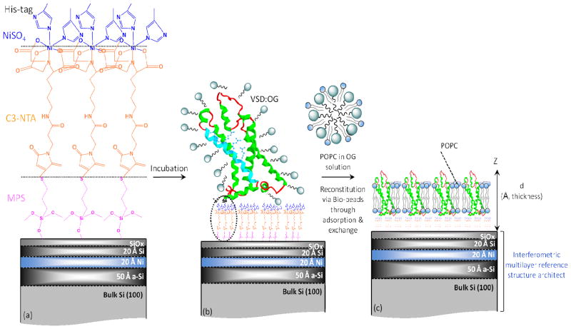
Si-Ni-Si multilayer inorganic substrates fabricated by magnetron sputtering were used as the reference structure for the neutron interferometry. They were immersed and sonicated in methanol, chloroform and acetone consecutively, each for 10 min to remove organic residues. They were subsequently alkylated with 3-mercaptopropyl trimethoxysilane (MPS) by boiling in 0.5% (v/v) MPS in iso-propanol for 10 min with reflux to control the macroscopic polarity of the substrate’s surface possessing the underlying multilayer reference structure. After rinsing with iso-propanol, the alkylated substrates were blow-dried with Ar gas and cured in an oven at 100–110 °C for 10 min promoting cross-linking as well as removal of organic residues. A monolayer of nitrilotriacetate (NTA) was subsequently chemisorbed onto the –SH endgroups of the alkylated surface by self-assembly from a maleimido-C3-NTA solution (2 mg/mL in Tris buffer, 30 min). Lastly, the NTA-terminated alkylated surface of the substrate was incubated with NiSO4 solution (50 mM in deionized water) for 30 min to coordinate a Ni2+ ion with the three carboxylate and one tertiary amine ligands provided by NTA (see Fig. 1).
Figure 1.
Schematic of the fabrication sequence outlining the self-assembly (SA) protocol. (a) A Si-Ni-Si multilayer reference structure with SiOx surface-layer, alkylated with a self assembled monolayer of mercapto-propyl-silane [MPS] ((MeO)3SiCH2CH2CHSH) to functionalize with thiol groups, is subsequently reacted with the linker maleimido–C3-NTA to provide free amino-nitrilotriacetate endgroups for ligation with Ni+2 ions, along with (b) histidine residues from the protein’s C-terminal His6-tag following VSD:OG incubation. (c) Reconstitution of vectorially-oriented VSD in a single phospholipid bilayer environment via exchange against H-POPC/OG (or D4-POPC/OG) in the presence of detergent-adsorbing Bio-beads. For a full-hydration environment, water is expected on both the proximal (near to) and distal (away from) substrate sides of the bilayer. The VSD is shown as ribbon representation of its crystal structure in a membrane-like environment.44
Protein Immobilization and Membrane Reconstitution
For VSD (or KvAP), the Self-Assembly (SA) approach is employed to form vectorially-oriented monolayers of the expressed protein tethered to the surface of inorganic substrates. For the SA approach (shown schematically in Fig. 1), the detergent OG (or DM)-solubilized VSD (or KvAP) is chemisorbed directly from isotropic solution via nickel coordination chemistry, utilizing the NTA (nitrilotriacetate) endgroups of the alkylating chains and the hexa-histidyl tag (His6-tag) of the protein as metal ligands, and subsequently rinsed. These SA-prepared monolayers of VSD:OG were exchanged against two different phospholipid-detergent micellar solutions (H-POPC:OG) and D4-POPC:OG) and the KvAP:DM monolayer against only one (H-POPC:DM) in the presence of Bio-Beads50, possessing a high detergent affinity through high surface area adsorption, and subsequently extensively washed with aqueous buffer only, intended to reconstitute a putative H-POPC (and D4-POPC) bilayer environment for the vectorially-oriented VSD (or KvAP) protein. Further details of preparation are provided in the Supporting Information.
Neutron Interferometry and Data Analyses
Neutron interferometry data (i.e. reflectivity enhanced by interference with the specular neutron reflectivity from the underlying inorganic multilayer substrate) from the self-assembled tethered VSD:OG monolayer and reconstituted VSD:H-POPC and VSD:D4-POPC membranes on Si-Ni-Si multilayer substrates hydrated with water-saturated gas (solid/vapor interface) or bulk aqueous media (solid/liquid interface) were acquired with the Advanced Neutron Diffractometer/Reflectometer (AND/R) in the guide-hall at the National Institute of Standards and Technology (NIST) Center for Neutron Research (NCNR, Gaithersburg-MD).32 These data were collected with monochromatic cold neutrons of wavelength of 5 Å (E=3.3 meV). Neutron interferometry data from the self-assembled tethered KvAP:DM monolayer and reconstituted KvAP:H-POPC membrane were acquired with the BL-4A Magnetism Reflectometer at the Spallation Neutron Source at Oak Ridge National Laboratory (Oak Ridge-TN) at the solid/liquid interface using polychromatic cold neutrons of mean wavelength 3.4 Å (E=3.65 meV).33, 34 The effective momentum transfer (Qz) range was ~0.005 to 0.30 Å−1 at NCNR and ~0.005 to 0.35 Å−1 at SNS. Details of the measurements are provided in the Supporting Information. Figures S3 and S4 therein illustrate the experimental neutron scattering geometry measuring reflectivity from vectorially-oriented VSD at solid/vapor and solid/liquid interfaces, respectively. The bulk solvent contrast for the solid/liquid interface was aqueous buffer with 100% D2O and 60% D2O/40% H2O (v/v). A schematic of the cross-section of the solid/liquid interface cell used at NCNR/NIST is shown in Fig. S4. The data were analyzed by methods analogous to those utilized for X-ray interferometry data at the solid/vapor and solid/liquid interfaces thoroughly described previously.28,35
Molecular Dynamics Simulations
Molecular dynamics simulations were performed on a fully-hydrated VSD:POPC membrane at the solid/liquid interface. Details are provided in the Supporting Information.
3. RESULTS AND DISCUSSION
Protein Immobilization and Membrane Reconstitution via Self-assembly
The Self-Assembly (SA) approach was originally developed to tether a membrane protein to the surface of a solid inorganic substrate via a bifunctional alkyl-chain, whose “headgroup” was specifically reactive toward the inorganic surface and whose “endgroup” was specifically reactive with a selected residue(s) on the protein’s surface.36 Such tethering thereby vectorially-oriented the protein on the inorganic surface allowing its profile structure to be investigated at the solid/moist He or saturated water vapor interface via specular X-ray and neutron reflectivity,37 the moist gas of sufficiently high humidity (~ 95 %) to retain the desired structure and thus the function of protein. The approach was recently extended to proteins prepared by biological expression, gainfully employing the reactivity of a hexa-histidyl tag (His6) appended to their N- or C-terminus (also used for the purpose of their purification via affinity chromatography) toward the iminotriactetate (NTA) endgroup in the presence of a coordinating transition metal.38 The SA approach is particularly relevant for the vectorial-orientation of detergent-solubilized integral membrane proteins, since the detergent can be subsequently exchanged for phospholipid(s) to create a realistic lipid bilayer environment for the protein analogous to that in a biological membrane.39 While the lipid bilayer itself can also be tethered to the surface of an inorganic substrate, it can only be utilized to vectorially-orient a water-soluble amphiphathic or amphiphilic protein within the bilayer,40 due to its instability to detergents. The SA approach was recently used to tether and vectorially-orient both the detergent-solubilized VSD of the prokaryotic Kv-channel KvAP, as well as the detergent-solubilized full-length KvAP itself, on the surface of silicon and specular X-ray reflectivity, enhanced by interferometry, was used to determine their respective profile structures at both the solid/moist He and solid/liquid interfaces.28 A judicious choice of the POPC (1-palmitoyl-2-oleoyl-sn-glycero-3-phosphocholine) as the phospholipid was used to reconstitute a putative lipid bilayer environment for the VSD protein, this pure lipid forming a 2-D fluid bilayer phase with a hydrocarbon core of sufficient thickness anticipated to “hydrophobically-match” the lateral non-polar surfaces of each protein vectorially-oriented within the bilayer. Comparison of the profile structures provided by X-ray interferometry at the solid:aqueous-liquid interface, prior to and following phospholipid exchange, indicated a successful reconstitution of the POPC bilayer environment of the VSD protein.28 However, the validity of this comparison for revealing the profile structure of the reconstituted POPC bilayer environment requires that both the protein structure, as well as its position relative to the inorganic surface, remains relatively unchanged between the two quite different environments.
Neutron Interferometry with Si-Ni-Si Multilayer Substrates
The Si-Ni-Si substrates utilized in these studies were selected for two key reasons. First, the neutron scattering-length density for Ni (9.41×10⁻⁶/Å−2) versus Si (2.1×10⁻⁶/Å−2) provides a contrast of ~4.5 which is roughly comparable to that for X-rays of ~3.0, and therefore such a multilayer substrate exhibits strong specular reflectivity for momentum transfer normal to the substrate surface for both cases. As a result, the specular reflectivity from a bio-organic overlayer on the substrate’s surface is dramatically enhanced through interference with that from the multilayer substrate also for both scattering cases.28 Importantly, this interference effect can also be used to phase the reflectivity data, thereby directly providing the respective scattering-length density profile for the multilayer substrate plus adsorbed or tethered bio-organic overlayer system.41 However, due to the low contrast between Si and Ni for incident neutron spins anti-parallel to the magnetization of the thin Ni layer (e.g. 20–30 Å), instead of magnetic phasing,42 we use a constrained refinement method for phasing the reflectivity data. This method utilizes unpolarized neutrons and both the known profile structure of the multilayer substrate and the finite extent of the gradient profile structure of the multilayer substrate plus bio-organic overlayer system, each determined independently, as key constraints.
Second, the Ni-layer is intended to ultimately serve as an effective working electrode in a three-electrode electrochemical cell, allowing application of transmembrane potentials across the reconstituted membrane on their surface. However, since the alkylation procedure used to tether the protein to the substrate requires a silicon oxide surface, the Ni layer is covered with a thin (20–30 Å) layer of Si oxidized to form a SiOx surface for the multilayer substrate. This has a significant consequence for the derivation of the scattering-length density profiles of the bio-organic overlayers chemisorbed tethered to the substrate’s surface, calculated as a Fourier representation using our phasing method, where the average scattering-length density of the overlayer is much less than the near-adjacent Ni-layer. Fourier transform truncation effects in these profiles arise from both the absence of meaningful data for profile structure determination for momentum transfer Qz less than the critical-angle for total neutron/X-ray reflection (Qc), designated as (Qz)min truncation, as well as for Qz larger than some (Qz)max, the latter (Qz)max truncation effect determining the spatial resolution (or minimum wavelength component) achieved in the derived profile. The former (Qz)min truncation effect is more pronounced in the neighborhood extending from the substrate’s surface in the derived profiles, due to the large scattering-length density of the nearby Ni-layer. Thus, the results described below employ difference scattering-length density (SLD) profiles, namely the difference between the SLD profile for the multilayer substrate with the tethered bio-organic overlayer (protein/detergent monolayer or reconstituted protein/lipid membrane) and the SLD profile for the substrate itself (bare), both in the same environment, namely either water-saturated gas (see Fig. S3) or bulk aqueous solvent (see Fig. S4). Notably, each of the two SLD profiles is calculated independently of the other. With all other aspects of the reflectivity experiment being identical for both environments, this procedure effectively removes the effect of (Qz)min truncation revealing an accurate scattering-length density profile of the desired bio-organic overlayer exhibiting only the effects of (Qz)max truncation, i.e. low-amplitude, minimum wavelength fluctuations. Model calculations justifying this approach for X-ray interferometry (applicable to neutron interferometry as well) are presented in the Supporting Information of the Ref. 28 (see Fig. S6).
The propagation of errors in the neutron reflectivity data into the Fourier representation of the scattering-length density profiles is explicitly addressed in the Supporting Information.
Part I: Profile structures of the VSD:OG Monolayer and the VSD:H-POPC and VSD-D4-POPC Membranes via SA at the Solid/Vapor Interface
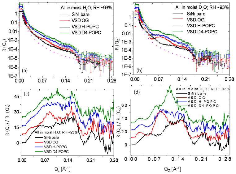
Figure 2 displays the background and footprint corrected (Figs. 2a and 2b) and Fresnel-normalized (Figs. 2c and 2d) neutron reflectivity data from representative specimens of the tethered monolayer of detergent-solubilized VSD (VSD:OG) and the subsequently reconstituted VSD:POPC membrane following exchange of the detergent for H-POPC or D4-POPC, hydrated with moist helium saturated with H2O or D2O (relative humidity, RH ~ 93%), along with similar data for the reference multilayer substrate itself in the same atmosphere. H2O to D2O exchange was monitored by observing the change in the reflectivity data at a selected value of Qz, and the equilibration was achieved within approximately 40 min. While the error bars are omitted for clarity, the signal-to-noise level obviously decreases with higher Qz (i.e. > 0.25 Å−1) as it is readily apparent from point-to-point fluctuations in the data along Qz. The Fresnel reflectivity from an ideal interface without surface roughness is also shown as the dotted line in Figs. 2a and 2b with a critical-angle for the silicon/vapor interface of Qc~ 0.0103 Å−1. These data exhibit significant stage-to-stage variation (e.g. OG versus H-POPC versus D4-POPC as well as H2O versus D2O in the gas-phase) well in excess of counting statistics throughout the accessed Qz range (0.005–0.30 Å−1), most evident by a switching of the interference effects between destructive and constructive in the neighborhood of Qz ~0.07–0.14 Å−1 (Figs. 2c and 2d). While the amplitude of the Fresnel–normalized reflectivity beyond Qz ~0.17 Å−1 relative to that at lower Qz is somewhat larger for H2O than D2O in the moist gas environment, the spatial resolution in the derived neutron scattering-length density profiles is limited by Qzmax ~0.28 Å−1 for both cases.
Figure 2.
The interferometric neutron reflectivity results from a typical VSD:OG specimen prepared via the self-assembly (SA) approach. Semi-log plots of the (a, b) background-corrected and (c, d) Fresnel-normalized reflectivity data, for the bare Si-Ni-Si substrate, tethered VSD:OG monolayer, and putative reconstituted VSD:H-POPC and VSD:D4-POPC bilayer membranes, at the solid/vapor interface utilizing a moist-gas environment with H2O or D2O at a Relative Humidity of ~93% (obtained using a saturated salt solution). The data are offset vertically for visual clarity. The dotted curve in (a) and (b) is the calculated Fresnel reflectivity function, RF. Error bars (all error bars herein represent the standard error) are included in (a) and (b), although the errors are also manifest in the point-to-point fluctuations in the data along Qz.
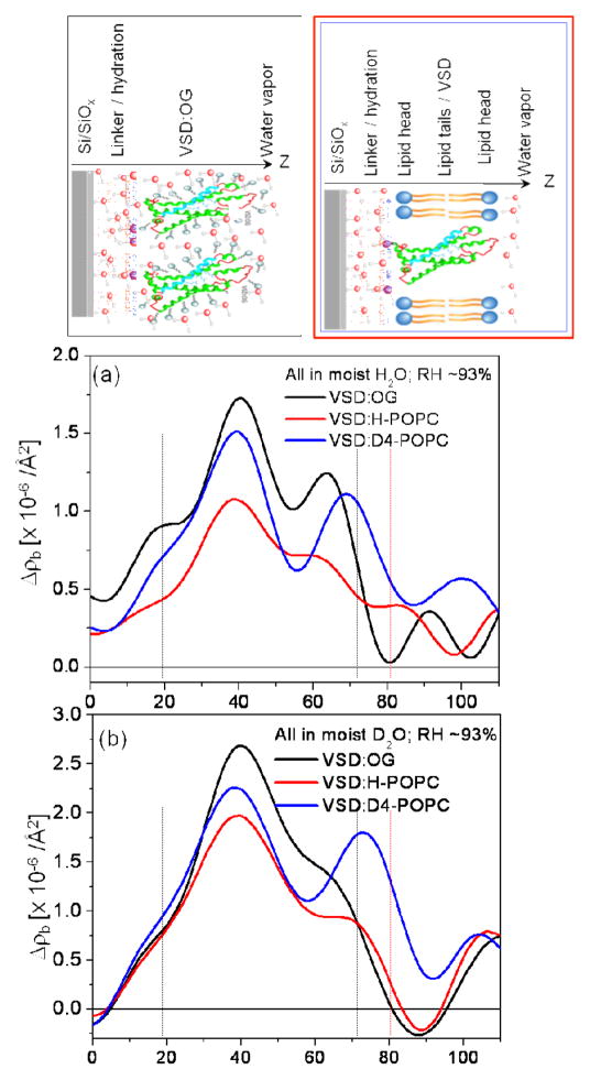
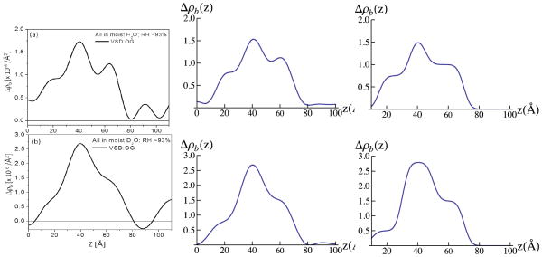
The difference neutron scattering-length density profiles Δρb(z), namely ρb(z) for the multilayer substrate with the tethered bio-organic overlayer minus ρb(z) for the multilayer substrate itself in the same environment, derived from these data for the tethered VSD:OG monolayer and the tethered VSD:POPC (H-POPC or D4-POPC) membranes for both moist gas environments (H2O and D2O) are shown in Fig. 3 [also see Fig. S5 for the scattering-length density profiles prior to generating the respective difference profiles, as well as the autocorrelation functions of the corresponding gradient profiles dρb(z)/dz providing one of the two constraints in the refinement analysis]. Simple cartoon representations for the tethered VSD:OG monolayer and the reconstituted VSD:POPC membrane are shown at the top of the Figure for reference.
Figure 3.
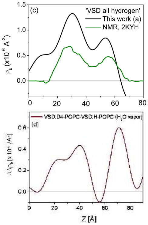
Summary of the neutron interferometry results at the solid/vapor interface in terms of the difference (not offset) scattering length density profiles Δρb(z) for the tethered VSD:OG monolayer and the reconstituted tethered VSD:H-POPC and VSD:D4-POPC membranes in (a) H2O- and (b) D2O-saturated moist-gas. (top) Schematic illustrations of the composite structures showing different components with respect to bilayer normal (z) approximately to scale. The VSD protein (green-turquoise ribbon-representation), OG detergent (gray), POPC lipid (blue-orange) and water molecules in the gas-phase (red and grey) are shown. The major features in the profile for the VSD:OG monolayer are similar to those for the VSD in phospholipid micelles calculated from the NMR solution structure (green; PDB accession code 2KYH) (c), both in profile extent (or dimension) and asymmetric features. (d) The D4-label profile for the H2O-saturated moist-gas environment determined via the double difference profile ΔΔρb(z) for Δρb(z) for the VSD:D4-POPC minus Δρb(z) for the VSD:H-POPC membrane. The dotted vertical lines are shown to visually guide compartmentalization of the different component(s).
VSD Profile Structure
The profile structure of the VSD/OG monolayer occurs within the region 10Å < z < 70Å of the difference profiles shown in Figure 3a and 3b. The multilayer substrate occurs for z < 0Å and the moist gas environment for z > 75Å at near-zero levels in these difference profiles. At this spatial resolution of ~ 20Å, the minimum wavelength Fourier component in the profiles, the VSD:OG profile structure is seen to be highly asymmetric and comprised of three principal regions (or features). The asymmetry for the two major features is predicted qualitatively, as shown in Fig. 3c, from the scattering-length density profiles calculated from the NMR structure of the VSD from the prokaryotic KvAP channel in phospholipid micelles43, with the VSD vectorially-oriented with respect to the inorganic surface anticipated by tethering the VSD via its C-terminal His6-tag. This level of agreement is sufficient to demonstrate the unidirectional vectorial orientation of the VSD protein at the solid/vapor interface. Note that for the VSD employed in this work, the main helices, namely helices S1-S4, form the 4-helix bundle structure of the VSD protein, with the bundle-axis oriented approximately normal to the plane of the inorganic surface. The VSD protein also includes the S4-S5 linker helix, which is amphipathic.44 In the NMR structure of the VSD in a phospholipid micelle, the S4-S5 linker helix is co-linear with the S4 helix, while in a phospholipid bilayer environment, it is likely that this S4-S5 linker helix lies in the plane perpendicular to the bundle axis (i.e. parallel to the plane of the bilayer surface). Here, for the tethered VSD:OG monolayer, the S4-S5 linker helix lies on the proximal side of the protein’s profile structure nearer the surface, it’s orientation with respect to the bundle axis affecting the asymmetry of the VSD’s profile structure (see Fig. 8). The lack of perfect agreement between the neutron and NMR profile structures likely arises from different orientations of the S4-S5 linker helix for the two environments.
Figure 8.
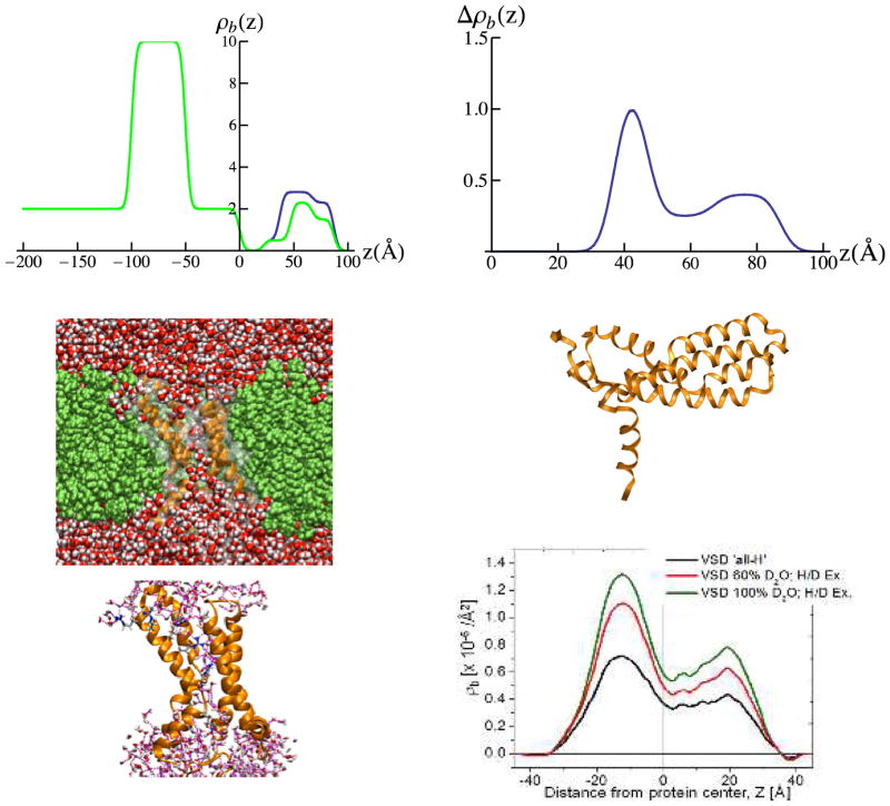
3-slab models for the VSD:OG monolayer for hydration with bulk aqueous buffer allowing for H-D exchange, but as if they were hydrated only with moist-gas (upper left-side), black for 100% D2O and green for 60% D2O/40% H2O for z > 0Å. The difference between these experimental 3-slab-model profiles is shown in the upper right-side panel, revealing the distribution of exchangeable hydrogen within the VSD itself. This experimental exchangeable hydrogen profile is in good agreement with that (right-side, lower at a resolution comparable to the experimental case) predicted by a molecular dynamics simulation of the VSD embedded in a fully-hydrated supported POPC bilayer (lower left-side). Configuration snapshots from the simulation (middle and lower left-side) reveal how H-D exchange may occur within the VSD itself. A cut-away view of the simulation system shows that when the VSD is embedded in a lipid bilayer, water molecules penetrate throughout forming an internal hydrogen bond network with a set of highly-conserved basic and acidic side chains. The middle right-side panel shows the VSD oriented with the membrane normal horizontal for comparison with the profiles shown above and below. In the simulation snapshots, the VSD is shown in ribbon (orange) and molecular surface representation (white, transparent). The lipid bilayer is shown in green in CPK representation. Waters and amino acid side chains are colored by atom (carbon, grey; nitrogen, blue; oxygen, red; hydrogen, white).
The principal features within these resolution-limited difference profiles can be precisely defined by modeling in terms of slabs of uniform scattering-length density. Unlike the more typical slab-model refinement, it is important to note that herein we refine the slab model against the derived difference profile, thereby modeling both the modulus and phase of the Fresnel-normalized reflectivity data from which it was derived, while the more typical refinement utilizes only the modulus data. In Fig. 4, we show the refined slab-models for the tethered VSD:OG monolayer for both moist environments (H2O and D2O), juxtaposed to their respective resolution-limited profiles calculated to the experimental resolution of 20Å. The latter are seen to be in near-perfect agreement with the respective experimentally determined difference profiles for the monolayer shown in Figs. 3a-3b. Thus, 3-slabs, each of uniform neutron scattering-length density, are seen to be sufficient to model the VSD:OG profile in saturated water vapor at this spatial resolution of ~ 20Å, which we will refer to subsequently to as a “3-slab model”. Importantly, we note that because these 3-slab model profiles for the VSD:OG monolayer (and their corresponding resolution-limited profiles) are distinctly different for hydration in moist-gas environment for D2O versus H2O necessarily requires that the differences arise from water penetration and subsequent H-D exchange within the VSD protein, since no rearrangement of the solvating OG molecules would be expected to occur upon the exchange at constant relative humidity. However, we will show in Part II that these profile structures for the VSD protein depend somewhat on the hydration state of the VSD:OG monolayer. As a result, these changes upon H-D exchange will be addressed in detail for the more relevant case of full-hydration with bulk aqueous buffer in Part II.
Figure 4.
Experimental neutron SLD profiles for the VSD:OG monolayer (black; left-side) at the solid/vapor interface with 100% H2O (upper) and 100% D2O (lower). 3-slab-model profiles (right-side), based on error-functions, and corresponding resolution-limited profiles (middle) calculated via Fourier transform-inverse Fourier transform with (Qz)max-truncation for the tethered VSD:OG monolayer. 3-slabs are sufficient to accurately model the experimental profiles for z > 0 Å, since their resolution-limited counterparts (middle) match the experimentally determined profiles (left). The propagation of errors in the neutron reflectivity data into the Fourier representation of the scattering-length density profiles, and their slab-models, is explicitly addressed in the Supporting Information. The differences in the profiles, here due to hydration with moist H2O or D2O, exceed the propagated error.
POPC Profile Structure
The profile structure of the VSD:POPC membrane occurs within the region 10Å < z < 80Å of the difference profiles shown in Figs. 3a and 3b, the reconstituted membrane appearing to be ~10 Å greater in thickness than the precursor VSD:OG monolayer. The difference profile for the VSD:D4-POPC membrane minus that for the VSD:H-POPC membrane results in the double-difference profile ΔΔρb(z), shown in Fig. 3d for vapor saturated with H2O. This is expected to reveal the distribution of POPC polar headgroups within the membrane profile, making the usual assumption that the exchange of H-POPC for D4-POPC is isomorphous. We note that one might expect this particular double difference profile to be similar for the moist environment saturated with H2O versus D2O vapor. However, while there are no exchangeable hydrogen atoms in the phospholipid molecule, a number of water molecules do associate with the polar headgroups (as well as with the loops connecting VSD’s helices on either side of the membrane). As a result, the D4 atoms in the headgroup of D4-POPC should make a larger relative contribution to this double difference profile using moist hydration with H2O vapor (i.e., the change due to the presence of the D4 label atoms is more apparent when they are embedded within a region of low scattering length density than within a region of high scattering length density). The headgroup profile for the POPC for hydration with saturated H2O vapor is thereby seen to be strongly asymmetric, the headgroups distributed over a broader region ~ 20Å in width on the proximal side of the membrane nearest the inorganic surface relative to those on the distal side, which are better localized over a narrower region ~ 10Å in width, in the headgroup profile. However, we will show in Part II that the profile structure for the POPC bilayer depends significantly on the hydration state of the VSD:POPC membrane. As a result, the bilayer structure will be addressed in detail for the more relevant case of full-hydration with bulk aqueous buffer in Part II.
Vapor-to-Bulk Water
Lastly, we note that the 3-slab-model profiles developed here for the VSD:OG monolayer in a moist environment provide an important basis (see Fig. S7 in the Supporting Information) for the interpretation of the experimental difference profiles derived for not only the same VSD:OG monolayer fully hydrated with bulk water, but also for the VSD:POPC membranes also fully hydrated with bulk water, as will be described in the following section.
Part II: Profile structures of the VSD:OG Monolayer and the VSD:H-POPC and VSD-D4-POPC Membranes via SA at the Solid/Liquid Interface
While integral membrane proteins can retain their function in lipid bilayer environments while hydrated only with moist gas at higher relative humidity (≥ 90%), thereby achieving partial to moderate levels of hydration,45,46 full hydration with bulk aqueous media on both proximal and distal sides of the membrane would be indispensable in order to a) retain the mobility of membrane molecular components (e.g. a 2-D fluid in-plane organization) minimally requiring a thin aqueous layer on either side 10–20Å in thickness, b) validate bilayer reconstitution upon exchange of detergent for phospholipid, c) investigate the effect(s) of full hydration on protein-lipid interaction and d) monitor protein structure under transmembrane electric potentials relevant to protein function, herein the conformational states associated with voltage-gating, for example. Moreover, despite the availability of atomic-resolution membrane protein structures from X-ray crystallography and our recent results at the solid/liquid interface using X-ray interferometry,28 direct structural information about membrane proteins in their native, fully-hydrated lipid bilayer environment is scarce and/or less than convincing. While X-ray and neutron reflectivity provide complementary structural information concerning membrane structure arising from the different atomic origin of their respective scattering, neutron reflectivity is particularly powerful for the structural investigation of such a bio-organic material due to the ability to vary the neutron scattering contrast of the hydrating aqueous phase coupled with the enhancement of the neutron scattering contrast of selected molecular, or sub-molecular, components via deuteration.
Since our ultimate goal is the investigation of the structures of such voltage-gated cation channel proteins as a function of transmembrane electric potential, it is essential that the protein dominate the membrane profile structure thereby requiring reconstituted membranes of minimal lipid content. Thus, the introduction of phospholipid for detergent via exchange represents a modification of a “membrane” profile structure (i.e. the VSD:OG monolayer) dominated by the protein, as opposed to the more usual case for membranes with much lower in-plane density of the protein, where the introduction of the protein represents a modification of a membrane profile structure dominated by the lipid. As a result, it is useful to first consider what we would expect for the profile structure of the precursor tethered VSD:OG monolayer hydrated with bulk aqueous media versus that determined in the prior section for hydration with moist gas, as shown in Fig. S7 in the Supporting Information. Our phasing method requires utilization of the Fresnel-normalized reflectivity data and therefore the critical-angle Qc must be observable in the reflectivity data for fitting the Fresnel function. For the VSD:OG monolayer and VSD:POPC membranes, this requires that the aqueous media contain at least 50% D2O. As a result, Fig.. S7 shows that the expected neutron scattering length density profile for the VSD:OG monolayer would be in negative contrast relative to the bulk 100% D2O and 60% D2O/40% H2O aqueous environments employed in this work, as opposed to being in positive contrast for the moist gas (or a bulk 100% H2O) environment. Note that the 3-slab models as shown here allow for no structural changes and no water penetration and/or H-D exchange in the VSD protein upon such an environmental change, and also assume that the VSD occupies 100% of the in-plane area within the VSD:OG monolayer.
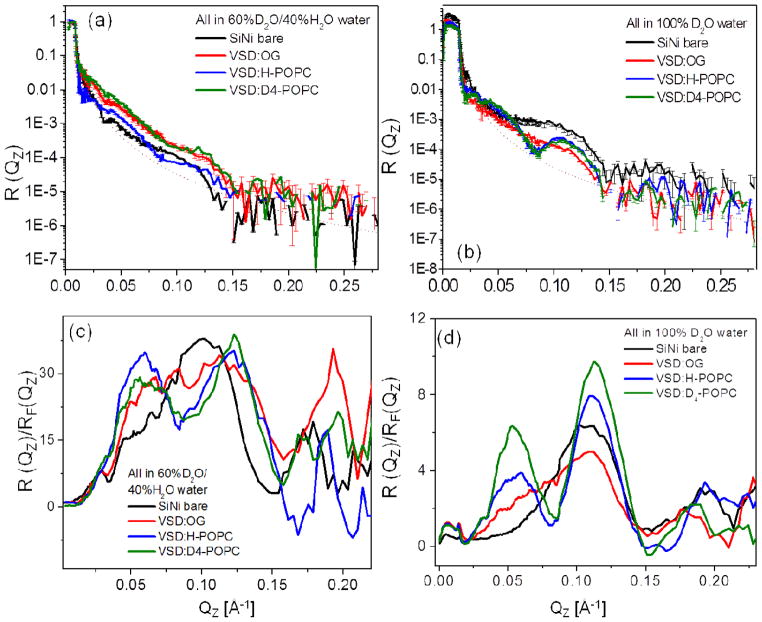
Figure 5 displays the background and footprint corrected (Figs. 5a and 5b) and Fresnel-normalized (Figs. 5c and 5d) neutron reflectivity data from representative specimens of the tethered monolayer of detergent-solubilized VSD (VSD:OG) and the subsequently reconstituted VSD:POPC membrane following exchange of the detergent for H-POPC or D4-POPC, hydrated with aqueous buffer in 60%D2O (Figs. 5a, c) and 100%D2O (Fig. 5b, d), each along with similar data for the reference multilayer substrate itself in the same environment. The signal-to-noise level obviously decreases with larger Qz (i.e. > 0.15 Å−1) as it is readily apparent from both the error bars shown and the point-to-point fluctuations in the data along Qz. The Fresnel reflectivity from an ideal interface without surface roughness is also shown as the dotted line in Figs. 5a and 5b, the critical-angle Qc for the silicon/water interface being dependent on the D2O/H2O ratio of the water environment (see below). Once again the data exhibit significant stage-to-stage variation (e.g. OG versus H-POPC versus D4-POPC as well as for the D2O/H2O ratio) well in excess of counting statistics throughout the accessed Qz range (0.005–0.225 Å−1), also most evident by a switching of the interference effects between destructive and constructive in the neighborhood of Qz ~ 0.06–0.12 Å−1 (Figs. 5c and 5d). While the amplitude of the Fresnel–normalized reflectivity beyond Qz ~0.15 Å−1 relative to that at lower Qz is somewhat larger for 60% D2O/40% H2O than for 100% D2O in the bulk aqueous environment, the spatial resolution in the derived neutron scattering-length density profiles is limited by Qzmax ~0.215 Å−1 for both cases. It’s noteworthy that the stage-to-stage changes in the neutron reflectivity shown here for full hydration with bulk aqueous media are substantially greater than those described previously28 for the X-ray case using essentially identical specimens (only smaller in area).
Figure 5.
The interferometric neutron reflectivity results from a typical VSD:OG specimen prepared via the self-assembly (SA) approach. Semi-log plots of the (a, b) background-corrected and (c, d) Fresnel-normalized reflectivity data, for the bare Si-Ni-Si substrate, tethered VSD:OG monolayer, and putative reconstituted VSD:H-POPC and VSD:D4-POPC bilayer membranes, at the solid/liquid interface utilizing an aqueous buffer environment with 100% D2O and 60% D2O/40% H2O. The data are offset vertically (a,b) for visual clarity. The dotted curve in (a) and (b) is the calculated Fresnel reflectivity function, RF. Error bars are included in (a) and (b), although the errors are also manifest in the point-to-point fluctuations in the data along Qz.
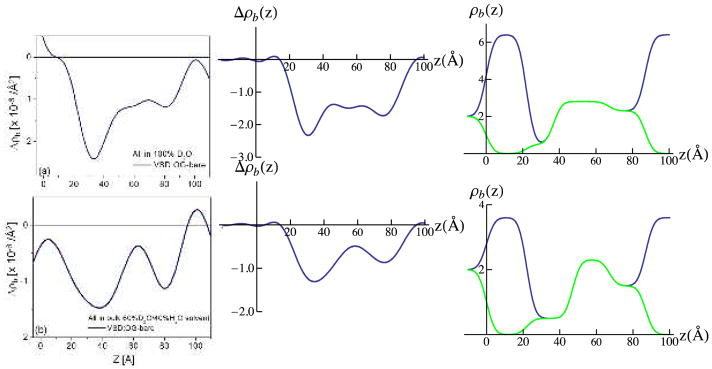
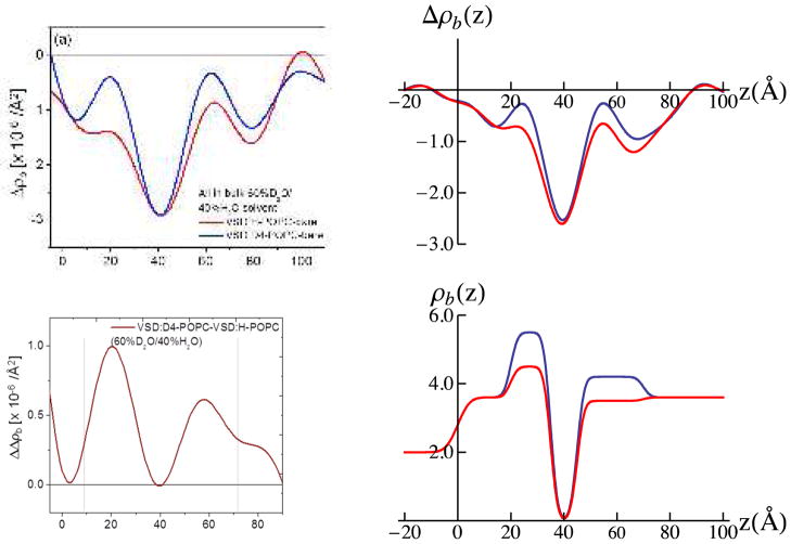
Figure 6 shows the difference neutron scattering-length density profiles Δρb(z), namely ρb(z) for the multilayer substrate with the tethered bio-organic overlayer minus ρb(z) for the multilayer substrate itself in the same environment, derived from these data for the tethered VSD:OG monolayer and the tethered VSD:POPC (H-POPC or D4-POPC) membranes for both bulk aqueous environments (100% D2O and 60% D2O/40% H2O). [also see Fig. S6 for the scattering-length density profiles prior to generating the respective difference profiles, as well as the autocorrelation functions of the corresponding gradient profiles dρb(z)/dz providing one of the two constraints in the refinement analysis]. Simple cartoon representations for the tethered VSD:OG monolayer and the tethered VSD:POPC membrane are shown at the top of the figure for reference.
Figure 6.
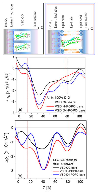
Summary of the neutron interferometry results at the solid/liquid interface in terms of the difference (not offset) scattering-length density profiles Δρb(z) for the tethered VSD:OG monolayer and the reconstituted tethered VSD:H-POPC and VSD:D4-POPC membranes in (a) aqueous buffer with 100% D2O and (b) aqueous buffer with 60% D2O/40% H2O. (top) Schematic illustrations of the composite structures showing different components with respect to bilayer normal (z) approximately to scale. The VSD protein (green-turquoise ribbon-representation), OG detergent (gray), POPC lipid (blue-orange) and bulk water (light-blue) are shown. The dotted vertical lines shown to visually guide compartmentalization of the different component(s)—see text. Note that the zero-level of scattering-length density on the ordinate-scale in these difference profiles is with respect to the average for bulk D2O at +6.36×10⁻⁶/Å2 for 100% D2O in (a) and for bulk 60% D2O/40% H2O at +3.56×10⁻⁶/Å2 in (b).
VSD Profile Structure
We first consider the difference profiles for the tethered VSD:OG monolayer in the two bulk aqueous environments. With reference to Fig. S7, it is immediately apparent that the average contrast between the VSD:OG monolayer and the aqueous environment is substantially less by about 50% compared with that predicted for the VSD:OG occupying 100% of the in-plane area of the monolayer. Water penetration of the monolayer between neighboring OG-solubilized VSD protein molecules would lower this contrast. From our prior work with these tethered VSD:OG monolayer and VSD:POPC membrane systems,28 we learned that for the latter, the VSD protein itself occupies only 50% of the available in-plane area when the precursor tethered VSD:OG monolayer is prepared by self-assembly. The reduction in contrast by about 50% noted above is fully consistent with this expectation. Nevertheless, the 3-slab model profiles shown in Fig. S7, allowing for this expected 50% reduction in contrast when placed in a bulk aqueous environment with the addition of a slab of bulk aqueous media fully hydrating either surface, both proximal and distal with respect to the substrate surface, can only qualitatively predict the features contained within the experimental VSD:OG monolayer profiles shown in Fig. 6 (not shown). However, with minor modifications, 3-slab model profiles for the VSD:OG monolayer itself, with a slab of bulk aqueous media fully hydrating either surface, can provide near-perfect agreement with the respective experimentally determined difference profiles for the monolayer, as shown in Fig. 7. These modifications include an increased total width and small changes in the amplitudes and widths of the slabs to allow for the possibility of H-D exchange, not at all surprising for full hydration versus partial hydration with a moist gas environment. The modifications required are apparent from comparison of Fig. 7 with Fig. S7, more so for hydration with 100% D2O.
Figure 7.
Experimental neutron SLD profiles for the VSD:OG monolayer (black; left-side) in 100% D2O buffer (upper) and 60% D2O/40 % H2O buffer (lower). 3-slab models for the VSD:OG monolayer (right-side) based on those shown in Figure 4, but allowing for H-D exchange and for a slight increase in monolayer thickness upon hydration with bulk aqueous buffer for 100% D2O (black;upper) and 60% D2O/40 % H2O (black;lower). The same 3-slab models as if they were hydrated instead with moist-gas are shown in green (by simply removing the water slabs either side of the monolayer), for comparison with those shown in Figures 4 & S7 to illustrate the changes induced by full hydration. Corresponding resolution-limited profiles (middle) calculated via Fourier transform-inverse Fourier transform with (Qz)max-truncation for the tethered VSD:OG monolayer for hydration in bulk aqueous buffer, assuming that the VSD:OG monolayer occupies only 50% of the monolayer in-plane area, the remainder occupied by the aqueous buffer. 3-slabs are sufficient to reasonably model the experimental profiles for z > 0 Å, since their resolution-limited counterparts (middle) nearly match the experimentally determined profiles (left). Precise matching is achieved with only minor modification of the proximal side of the central (of the three) slab by introduction of a fourth slab (not shown). The propagation of errors in the neutron reflectivity data into the Fourier representation of the scattering-length density profiles, and their slab-models, is explicitly addressed in the Supporting Information. The differences in the profiles, here due to hydration with H2O or D2O, exceed the propagated error.
Importantly, we note that these 3-slab model profiles for the VSD:OG monolayer (and their corresponding resolution-limited profiles) are distinctly different for hydration in bulk aqueous buffer environments for 100% D2O versus 60% D2O/40% H2O. This necessarily requires that water penetration and subsequent H-D exchange occur within the VSD protein, since no rearrangement of the solvating OG molecules would be expected to result from a change in D2O/H2O content in the liquid phase. Given this successful modeling of the experimental difference profiles for the tethered VSD:OG monolayer, the two slabs representing the bulk aqueous media can be simply removed from the model to reveal the penetration of water into the VSD protein and subsequent H-D exchange, as shown in Fig. 8. The difference between the 3-slab model for the VSD:OG monolayer in 100% D2O minus 60% D2O/40% H2O provides an equivalent experimental H-D exchange profile [i.e. exchangeable hydrogen for deuterium (HDX)].49 Importantly, the shape of this experimental H-D exchange profile (i.e., in terms of the positions and relative amplitudes of its features) agrees very well with that predicted from MD simulations of the VSD protein in a fully-hydrated POPC bilayer membrane also shown in Fig. 8. The H-D exchange profile from the simulation assumed that all possible exchangeable hydrogens within the VSD protein would in fact exchange based on their transient access to water over the course of the trajectory. This extensive access would not be expected to occur without the presence of a water channel/pore spanning the core of the VSD structure31, since the lateral surfaces of the VSD should be solvated exclusively by the hydrocarbon chains of the OG detergent within the VSD:OG monolayer. The significance of such a water channel/pore within the core of the VSD structure is suggested by the VSD’s homology with voltage-gated hydrogen channels such as Hv1, where the channel would provide a proton conduction pathway31. The experimental H-D exchange profile indicates a average change in the neutron scattering-length density of the VSD itself of 0.859 × 10⁻⁶/Å2, the average over the length of the profile, upon changing from the 60%D2O/40% H2O to 100% D2O bulk aqueous environment. For a mass density of 1.35 gm/cm3 for the VSD protein and a composition of C779N216O206S2H1284, a change of 10 hydrogen atoms to deuterium would result in an average neutron scattering-length density change of 0.0467 × 10⁻⁶/Å2. Thus, the change in the experimental H-D profile requires an exchange of 184 hydrogen atoms out of the 259 that could potentially exchange if exposed to water, or 71% of the exchangeable hydrogen. The MD simulations provide key insight into water’s access to the protein’s interior within the membrane, including via H-bond networks associated with the VSD’s water pore, collectively described as the protein-solvent energy landscape.47
POPC Profile Structure
We next consider the difference profiles for the reconstituted VSD:POPC membrane in the two bulk aqueous environments. With 100% D2O water hydrating both the proximal and distal side of the membrane, we would not expect much difference between D4-POPC and H-POPC, given that the D4 moiety in the vicinity of choline group occurs in the highly hydrated polar headgroup region of the bilayer. Such a difference would become progressively more pronounced as the average scattering length density of the aqueous medium approaches that of the membrane, the contrast match point. For our case, full hydration 60% D2O/40% H2O is as close as can be attained employing our phasing procedure. In Fig. 9, we show the experimental difference neutron scattering length density profiles Δρb(z) for the VSD:D4-POPC and VSD:H-POPC membrane, along with the double difference profile ΔΔρb(z) for the former minus the latter, expected to reveal the distribution of the D4-label across the profile. This D4-label profile, e.g. essentially that of the POPC polar headgroups, is seen to be highly asymmetric, the headgroup layer more narrowly distributed on the proximal side and more broadly distributed on the distal side of the reconstituted POPC bilayer environment for the vectorially-oriented VSD protein, a majority of the headgroups separated by ~ 40Å across the profile. While this asymmetry is quite different from that for only partial hydration with saturated vapor (shown in Fig. 3d), not surprisingly, it is virtually identical to that for the same bulk aqueous environment as suggested by the previous X-ray interferometry experiments.28 The detailed nature of this asymmetry is also revealed using a 3-slab model for the reconstituted POPC bilayer (D4-POPC versus H-POPC), the model refinement guided by the experimental double difference profile, as shown in Fig. 9. Assuming a) that the VSD and POPC each occupy 50% of the in-plane area within the reconstituted VSD:POPC membrane, the POPC replacing OG and water and b) the 3-slab model for the VSD profile determined for the VSD:OG monolayer in the same environment from Fig. 7, the resulting resolution-limited difference profiles shown in Fig. 9 are seen to reasonably agree well with their experimental counterparts. Thus, from the refined 3-slab models for the POPC bilayer, we see that the POPC bilayer as reconstituted in the VSD:POPC membrane is highly perturbed relative to that expected for a pure phospholipid bilayer. With the expected total thickness of ~50Å, while the polar headgroups are distributed more narrowly over only ~ 10Å on the proximal side, they are distributed more broadly over ~ 20Å on the distal side of the membrane, with an intervening relatively narrow region of pure hydrocarbon chains only ~ 10Å in thickness not overlapped by polar headgroups in this profile, as averaged via projection along the plane of the membrane. The relatively thin pure hydrocarbon layer, coupled with the broader headgroup distribution on the distal side of the membrane profile and total bilayer thickness noted, most likely arises from chain inter-digitation in the profile projection. This is not surprising considering the relatively low lipid content of only 12–13 POPC molecules/VSD molecule on a per monolayer basis.28 We note that utilizing these 3-slab models for the reconstituted POPC bilayer, but in 100% D2O and again assuming a) that the VSD and POPC each occupy 50% of the in-plane area within the reconstituted VSD:POPC membrane, the POPC replacing OG and water, and b) the 3-slab model for the VSD profile determined for the VSD:OG monolayer in the same environment from Fig. 7, that the resulting resolution-limited difference profiles also agree reasonably well (not shown) with their experimental counterparts shown in Fig. 6. However, as anticipated for hydration with bulk aqueous 100% D2O case described at the beginning of this paragraph, the double difference resolution-limited profile resulting from the resolution-limited profile for the reconstituted VSD:POPC membrane with D4-POPC minus that with H-POPC does not reveal the D4-label profile nearly as well as for hydration with 60% D2O/40%H2O, especially upon the introduction of any error in modeling these profiles.
Figure 9.
Experimental neutron SLD profiles for the VSD:POPC membrane at the solid/liquid interface (left-side, upper) in 60% D2O/40% H2O buffer for D-POPC (blue) and H-POPC (red). The difference between these two profiles reveals the experimental D4-label distribution within the VSD:POPC membrane profile (left-side, lower). 3-slab models are shown (right-side, lower), developed from this D4-label distribution, for the D4-POPC (blue) and H-POPC (red) bilayer within the VSD:POPC membrane. Combining these 3-slab models for the POPC bilayer within the membrane with the VSD profile shown in Figure 7 (middle, lower) for hydration with 60% D2O/40 % H2O buffer, assuming the VSD and POPC each occupy 50% of the membrane in-plane area in the area-weighted sum of the VSD and POPC profiles, results in the resolution-limited neutron SLD profiles shown upper right-side, which compare reasonably well their experimental counterparts shown upper left-side. This comparison, together with the experimental D4-label distribution, guided the refinement of the 3-slab models for the POPC bilayer within the VSD:POPC membrane. The propagation of errors in the neutron reflectivity data into the Fourier representation of the scattering-length density profiles, and their slab-models, is explicitly addressed in the Supporting Information. The differences in the profiles, here due to D4-POPC or H-POPC, exceed the propagated error.
H-D Exchange Profile
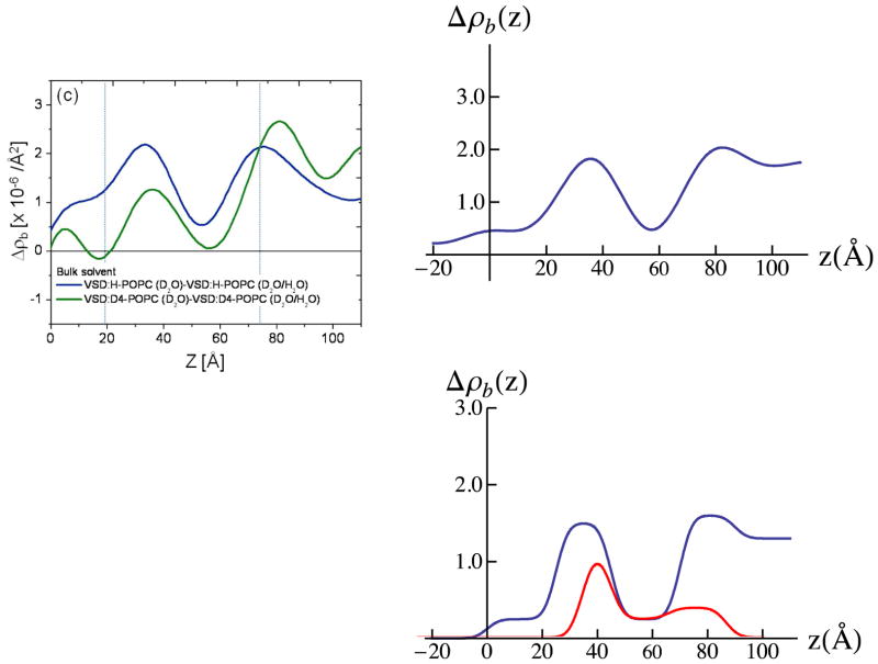
Full hydration of the membrane surface is essential for maintaining the structure and function of membrane proteins. This would include at least the first hydration layer and most likely, the next two-three hydration layers before bulk water properties would be expected. It is therefore important to address the issue of hydration for such reconstituted VSD:POPC membranes, especially with respect to their proximal surface. In this context, we next consider the H-D exchange profile for the reconstituted VSD:POPC membrane. In Fig. 10 we show the difference profiles for the reconstituted VSD:POPC membranes fully-hydrated with 100% D2O versus 60% D2O/40%H2O. Ideally, the H-D exchange profile for D4-POPC would be identical to that for H-POPC, assuming that the exchange of D4-POPC for H-POPC was perfectly isomorphous. While the exchange profiles are qualitatively similar, they are certainly not identical. However, the two exchange profiles do represent two independent measurements, and we have selected the average of these two profiles for further analysis. A 4-slab model for the average H-D exchange profile for the VSD:D4-POPC membrane is shown in Fig. 10, and the corresponding resolution-limited profile shown is in good agreement with the experimental average H-D exchange profile. Although the range of uncertainty in this average H-D exchange profile could be as large as the difference between the two experimental exchange profiles, we suspect that the difference is instead dominated by a lack of perfect isomorphism between the two membranes reconstituted with D4-POPC vs. H-POPC. We first note that the amount of H-D exchange in the VSD itself completely accounts for all of the exchange over the interior region of the membrane (e.g. 45Å < z < 70Å). This would not be expected to occur without the presence of a water pore spanning the core of the VSD structure, since the lateral surfaces of the VSD should be solvated exclusively by the hydrocarbon chains of the POPC within the VSD:POPC membrane.31 It also accounts for a substantial portion of the exchange at the proximal surface of the membrane over the region 35Å < z < 45Å). Notably, the 10Å-wide adjacent region closer to the substrate surface for 25Å < z < 30Å achieves a level of hydration approaching that of bulk water (as for z > 80Å), this level being limited presumably only by the presence of the loops connecting the helices of the VSD and the POPC polar headgroups (see Fig. S8 in the Supporting Information) within this region of the profile. To be more specific, again assuming that VSD and the associated POPC molecules each occupy 750Å2 in the membrane plane, this 10Å-wide slab would contain ~375 water molecules. As a result, there would be about fifteen (15) water molecules/POPC polar headgroup at this level of hydration if the water molecules were divided equally between the areas occupied by the VSD and the 12–13 POPC molecules in the membrane plane.
Figure 10.
Experimental total H-D exchange profiles for the VSD:POPC membranes (left-side) with D4-POPC (green) or H-POPC (blue) obtained by subtraction of the experimental neutron SLD profile for hydration with 100% D2O minus that for 60% D2O/40% H2O shown in Figure 6. 4-slab model for the total H-D exchange profile for the average of the D4-POPC and H-POPC cases (lower right-side) and its resolution-limited counterpart (upper right-side), the latter seen to be in good agreement with the average of the experimental total H-D exchange profiles (left-side). The H-D exchange profile for the VSD itself, from Figure 8, is also shown (red, lower right-side), which is seen to account for the total H-D exchange profile (blue) over the central region of the membrane. The propagation of errors in the neutron reflectivity data into the Fourier representation of the scattering-length density profiles, and their slab-models, is explicitly addressed in the Supporting Information.
Lastly, the utilization of neutron interferometry, coupled with selective deuteration of the POPC headgroup in the vicinity of choline moiety and variation of the contrast of the aqueous medium via manipulation of the D2O/H2O ratio, has provided a determination of the separate profile structures of the VSD protein and the phospholipid bilayer within the reconstituted membrane, as well as the distribution of exchangeable hydrogen within the profile structures of both the VSD itself and the membrane. A direct comparison, via juxtaposition, of the separate profile structures of the membrane components using the refined slab-models, is shown in Fig. S8 of the Supporting Information. The upper and middle panels of the figure show the separate neutron scattering-length density profiles of the VSD protein and the POPC bilayer within the membrane. The lower panel shows a superposition of the slab-model for the H-D exchange profile for the VSD itself, from Fig. 8 and the slab-model for the H-D exchange profile for the VSD:POPC membrane from Fig. 10.
Part III: Profile structures of the KvAP:DM Monolayer and the KvAP:H-POPC Membrane via SA at the Solid/Liquid Interface
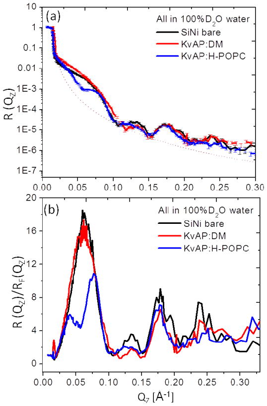
We have also initiated analogous studies of the full-length KvAP channel protein including the tethered KvAP:DM monolayer and the KvAP:H-POPC membrane at the solid/liquid interface in bulk aqueous buffer for 100% D2O. These were prepared in a manner completely analogous to that described for the VSD protein. Figure 11 shows the footprint and background corrected and Fresnel-normalized reflectivity neutron reflectometry data again demonstrating systematic stage-to-stage changes, more evident in the Fresnel-normalized reflectivity, observed for the progression from the Si-Ni-Si substrate to the tethered KvAP:DM monolayer and to the KvAP:H-POPC membrane, following DM-POPC exchange, all in aqueous buffer for 100% D2O. These data were acquired with the BL-4A reflectometer (horizontal reflection plane) at the SNS/ORNL with the monolayer and membrane specimens tethered to the surface of Si-Ni-Si multilayer substrates having 30 Å thickness for the Ni and Si layers. The stage-to-stage changes in the reflectivity are as significant and as readily apparent as for the analogous VSD systems measured in these bulk aqueous media throughout the accessed Qz range of ~0.32 Å−1. We note that the neutron reflectivity data exhibit improved signal-noise level over the larger values of momentum transfer accessed, namely 0.15Å−1 < Qz < 0.30Å−1, utilizing the pulsed polychromatic spallation neutrons at the SNS/ORNL as compared with continuous, monochromatic cold neutrons at the NCNR/NIST. However determining the momentum transfer value for the critical-angle, Qc, can be more challenging.
Figure 11.
The interferometric neutron reflectivity results from a typical KvAP:DM specimen prepared via the self-assembly (SA) approach. Semi-log plots of the (a, b) background-corrected and (c, d) Fresnel-normalized reflectivity data, for the bare Si-Ni-Si substrate, tethered KvAP:DM monolayer, and putative reconstituted KvAP:H-POPC bilayer membrane, in bulk aqueous buffer environments with 100% D2O. The dotted curve in (a) is the calculated Fresnel reflectivity function, RF. Error bars are shown in (a), although the errors are also manifest in the point-to-point fluctuations in the data along Qz.
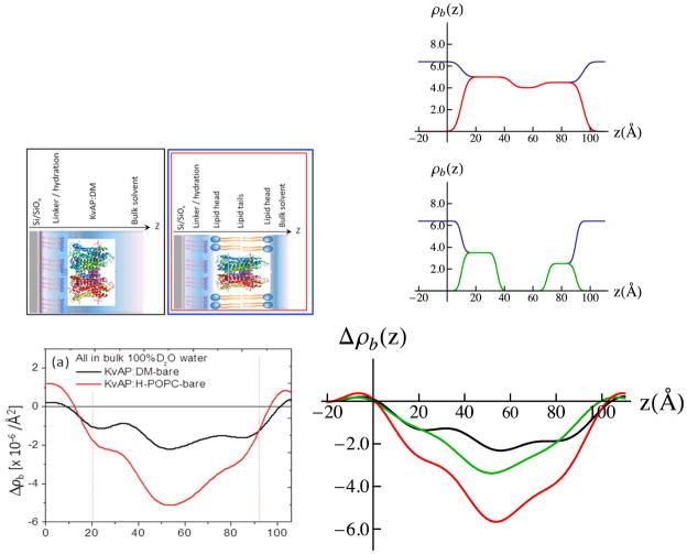
The usual difference neutron scattering-length density profiles Δρb(z) for the tethered KvAP:DM monolayer and the reconstituted KvAP:H-POPC membrane are shown in Fig. 12. We first consider that for the tethered KvAP:DM monolayer. The nature of the difference profile suggests that it can be modeled as three slabs of uniform neutron scattering-length density, all in negative contrast with respect to the average scattering-length density of the aqueous environment at 100% D2O. The refined 3-slab model for the KvAP protein is shown in Fig. 12, along with the corresponding resolution-limited profile for the protein, the latter seen to be in good agreement with the experimental difference profile for the KvAP:DM monolayer. With data available only for the reconstituted KvAP:H-POPC membrane in the same environment, a reasonable 3-slab model for the POPC bilayer within the membrane was refined, combining the corresponding resolution-limited profile for the POPC bilayer model with that for the KvAP protein, assuming that the KvAP protein and POPC bilayer each occupy ~ 50% of the membrane in-plane area in the weighted sum, to predict the experimental counterpart. Reasonably good agreement was achieved, as shown in Fig. 12. We also note that the resolution-limited profile for the refined 3-slab model of the phospholipid bilayer also agrees well with that calculated by subtraction of the experimental difference profile for the KvAP:DM monolayer from that for the KvAP:H-POPC membrane (not shown). This double difference profile ΔΔρb(z) would also be expected to reveal the profile of the reconstituted POPC bilayer within the membrane, with the necessary assumption that both the profile structure of the KvAP protein and its position with respect to the substrate surface remain unchanged upon conversion of the DM environment to that of POPC. The relative in-plane occupancies utilized were determined from MD simulations for the KvAP protein within a fully-hydrated POPC bilayer (see Supporting Information for details), assuming that the KvAP:DM precursor monolayer was densely-packed resulting in a minimal solvation of the KvAP protein by the POPC lipid molecules in the reconstituted membrane upon exchange of the DM detergent for the phospholipid. Selecting minimal solvation of the KvAP with POPC in the simulation resulted in a cylindrical complex with an average area/KvAP:POPC of 8,030 Å2. The KvAP:POPC mole ratio for the minimally-solvated protein was 1:68 on a per monolayer basis. An area of ~59 Å2/POPC molecule provides a total area of 3,835 Å2 occupied by the phospholipid leaving 4,195 Å2 occupied by the protein, namely each component occupying ~50% of the membrane’s in-plane area.
Figure 12.
Experimental difference neutron SLD profiles for the tethered KvAP:DM monolayer and reconstituted KvAP:H-POPC membrane are shown lower left-side, with simple cartoon representations of the systems directly above. In the right-side, upper panel, the refined 3-slab model for the KvAP:VSD is shown in 100%D2O bulk aqueous buffer (black) vs. that as if at the solid/vapor interface in a moist-gas environment (red). In the right-side, middle panel, the refined 3-slab model for the POPC bilayer within the KvAP:H-POPC membrane in shown in 100%D2O bulk aqueous buffer (black) vs. that as if in a moist-gas environment (green). In the right-side, lower panel, the corresponding resolution-limited neutron SLD profiles, calculated via Fourier transform-inverse Fourier transform with (Qz)max-truncation for the 3-slab model for the KvAP:DM monolayer (black) and the KvAP:H-POPC membrane (red) are shown providing reasonably good agreement with their respective experimental counterparts (left-side, lower panel), along with that for the POPC bilayer within the membrane (green). The resolution-limited profile for the membrane (red) was again calculated, assuming that the KvAP protein and POPC bilayer each occupied 50% of the membrane in-plane area in the area-weighted sum of the KvAP (black) and H-POPC (green) profiles. Refinement of the 3-slab models for the KvAP protein and the POPC bilayer was guided in this case only by the comparisons of the experimental profiles with the resolution-limited profiles corresponding to the slab-models for the KvAP:DM monolayer and KvAP:H-POPC membrane systems. The propagation of errors in the neutron reflectivity data into the Fourier representation of the scattering-length density profiles, and their slab-models, is explicitly addressed in the Supporting Information.
The POPC bilayer environment for the KvAP protein within the reconstituted membrane is thereby seen to be more typical compared to the profile of the pure POPC bilayer, unlike the case for the VSD itself described in Part II. Notably, the core comprised of pure hydrocarbon chains is ~25Å in thickness, although the polar headgroups remain more broadly distributed in the profile at either surface of the bilayer, namely over ~20Å instead of ~ 10Å. Interestingly, solvation of the lateral surfaces of the KvAP homo-tetramer with minimal POPC results in a less perturbed phospholipid bilayer environment for the full-length protein compared with that for the VSD itself. Nevertheless, further characterization via neutron reflectivity utilizing specifically deuterated phospholipid is warranted.
4. CONCLUSION
In this work, we have determined the profile structure of the precursor, tethered VSD:OG monolayer and subsequently reconstituted VSD:POPC membrane, both either partially-hydrated with water-saturated gas or fully-hydrated with bulk aqueous media, in substantially greater sub-molecular detail than previously achieved. We demonstrated the unique vectorial orientation of the VSD and the retention of its molecular conformation (secondary and folded 3-D tertiary structure) manifest in the asymmetric profile of the protein within this reconstituted single bilayer membrane system. We definitively characterized the asymmetric phospholipid bilayer solvating the lateral surfaces of the VSD protein. The profile structures of both the VSD protein and the phospholipid bilayer were thereby shown to exhibit significant dependence on the hydration state of the membrane. We also characterized the distribution of hydration water and exchangeable hydrogen throughout the profile structure of both VSD itself and the VSD:POPC membrane for the fully-hydrated case. The two experimentally-determined water and exchangeable hydrogen distribution profiles are consistent with the existence of a water pore within the core of the VSD, first indicated by molecular dynamics simulations of the VSD protein vectorially-oriented within fully hydrated POPC bilayer membranes. These results derived not only from the utilization of neutron interferometry, coupled with solvent contrast variation and selective deuteration in the polar headgroup of the POPC component, but also because the vectorial orientation of the VSD protein within the membrane was necessarily unidirectional, as dictated by the mode of tethering for the precursor VSD:OG monolayer to the surface of the inorganic substrate. Such results cannot be achieved utilizing more typical membrane reconstitution approaches that generally result in the vectorial orientation of the protein being bi-directional, that is, with equally populated opposed unidirectional orientations, which results in the determined profile structures of both the protein and the phospholipid being necessarily completely symmetric about the center of the membrane profile structure.48
Some results were also provided for the full-length KvAP protein for both the tethered KvAP:DM monolayer and the subsequently reconstituted KvPA:POPC membrane. While these are not yet as extensive as those described for the VSD, they demonstrate a successful reconstitution of a phospholipid bilayer environment for the vectorially-oriented KvAP protein, more similar to that of a pure phospholipid bilayer than that for only the VSD itself.
Supplementary Material
Acknowledgments
We thank Kenton Swartz and Dimitry Krepkiy (NINDS/NIH, Bethesda, MD) for providing VSD:OG and Manuel Covarrubias and Aditya Bhattacharji (Jefferson Medical College, Thomas Jefferson University, Philadelphia, PA) for providing KvAP:DM proteins. Chian Liu (X-ray Science Division, Advanced Photon Source, Argonne National Laboratory) provided the fabrication of the inorganic multilayer (Si-Ni-Si) substrates and Richard Chamberlain and Chris Carroll (University of California Irvine, CA) synthesized D4-POPC. We also thank Charles Majkrzak (NIST Center for Neutron Research) for improving the design of solid/liquid interface cell accommodating our smaller substrates at NIST/NCNR, David Worcester for technical assistance at NIST/NCNR, Bill Pennie for fabricating the liquid cell used to measure reflectivity in a bulk aqueous environment at the Spallation Neutron Source at the Oak Ridge National Laboratory, and Valeria Lauter, Haile Ambaye and Richard Goyette (all at the SNS/ORNL) for technical assistance with the initial sample alignment and data reduction software. The authors (S.G. and J.K.B) acknowledge the support of the National Institute of Standards and Technology (Gaithersburg, MD), U.S. Department of Commerce, for use of the neutron research facilities used in a majority of this work, with additional support for the construction of the AND/R instrument from the Cold Neutrons in Biology and Technology Partnership funded via the NIH RR14812 grant, and use of the Oak Ridge National Laboratory Spallation Neutron Source, which is supported by the Scientific Users Facility Division through the U.S. Department of Energy, made possible through the user award no. IPTS-3952 to S.G and J.K.B. Authors S.G., A.F., D.T. and J.K.B acknowledge financial support from the NIH/NINDS Program Project Grant NIH P01 GM086685.
Footnotes
Supporting Information. Details of experimental procedures, autocorrelation (or Patterson) functions, absolute neutron scattering-length density profiles derived from the neutron interferometry data, and the propagation of errors from the interferometry data into the derived neutron scattering-length density profiles. This material will be available free of charge via the Internet at http://pubs.acs.org.
References
- 1.Hodgkin AL, Huxley AF. J Physiol. 1952;117:500–544. doi: 10.1113/jphysiol.1952.sp004764. [DOI] [PMC free article] [PubMed] [Google Scholar]
- 2.Bezanilla F. Physiol Rev. 2000;80:555–592. doi: 10.1152/physrev.2000.80.2.555. [DOI] [PubMed] [Google Scholar]
- 3.Hill B. Ion Channels of Excitable Membranes 3e. Sinauer Associates Inc; 2001. [Google Scholar]
- 4.Aschcroft FM. Ion channels and Diseases. Academic Press; San Diego, CA: 2000. [Google Scholar]
- 5.Borjesson SI, Elinder F. Cell Biochem Biophys. 2008;52:149–174. doi: 10.1007/s12013-008-9032-5. [DOI] [PubMed] [Google Scholar]
- 6.Lehmann-Horn F, Jurkat-Rott K. Physiol Rev. 1999;79:1317–1372. doi: 10.1152/physrev.1999.79.4.1317. [DOI] [PubMed] [Google Scholar]
- 7.Garcia ML, Kaczorowski GJ. Science’s stke. 2005;302:pe46-1–pe46-3. doi: 10.1126/stke.stke.3022005pe46. [DOI] [PubMed] [Google Scholar]
- 8.Jiang Y, Ruta V, Chen J, Lee A, MacKinnon R. Nature. 2003;423:42–48. doi: 10.1038/nature01581. [DOI] [PubMed] [Google Scholar]
- 9.Bhattacharji A, Kaplan B, Harris T, Qu XG, Germann MW, Covarrubias M. Molecular Pharmacology. 2006;70:1542–1554. doi: 10.1124/mol.106.026187. [DOI] [PubMed] [Google Scholar]
- 10.Alkire MT, Asher CD, Franciscus AM, Hahn EL. Anesthesiology. 2009;110:766–773. doi: 10.1097/aln.0b013e31819c461c. [DOI] [PubMed] [Google Scholar]
- 11.Jiang Y, Lee A, MacKinnon R. Nature. 2003;423:33–41. doi: 10.1038/nature01580. [DOI] [PubMed] [Google Scholar]
- 12.Doyle DA, Cabral JM, Pfuetzner RA, Kuo A, Gulbis JM, Cohen SL, Chait BT, MacKinnon R. Science. 1998;280:69–77. doi: 10.1126/science.280.5360.69. [DOI] [PubMed] [Google Scholar]
- 13.Long SB, Campbell EB, MacKinnon R. Science. 2005;309:897–903. doi: 10.1126/science.1116269. [DOI] [PubMed] [Google Scholar]
- 14.Chen X, Wang Q, Ma J. Proc Natl Acad Sci USA. 2010;107:11352–11357. doi: 10.1073/pnas.1000142107. [DOI] [PMC free article] [PubMed] [Google Scholar]
- 15.Mackinnon R. Angew Chem Int Ed. 2004;43:4265–4277. doi: 10.1002/anie.200400662. [DOI] [PubMed] [Google Scholar]
- 16.Long SB, Tao X, Campbell EB, MacKinnon R. Nature. 2007;450:376–382. doi: 10.1038/nature06265. [DOI] [PubMed] [Google Scholar]
- 17.Cuello LG, Jogini V, Cortes DM, Pan AC, Gagnon DG, Dalmas O, Perozo E. Nature Letters. 2010;466:272–275. doi: 10.1038/nature09136. [DOI] [PMC free article] [PubMed] [Google Scholar]
- 18.Yeheskei A, Haliloglu T, Tal NB. Biophysical Journal. 2010;98:2179–2188. doi: 10.1016/j.bpj.2010.01.049. [DOI] [PMC free article] [PubMed] [Google Scholar]
- 19.Ledwell JL, Aldrich RW. J Gen Physiol. 1999;113:389–414. doi: 10.1085/jgp.113.3.389. [DOI] [PMC free article] [PubMed] [Google Scholar]
- 20.Tombola F, Pathak MM, Isacoff EY. Ann Rev Cell Dev Biol. 2006;22:23–52. doi: 10.1146/annurev.cellbio.21.020404.145837. [DOI] [PubMed] [Google Scholar]
- 21.Yellen G. Quaterly Rev of Biophys. 1998;31:239–295. doi: 10.1017/s0033583598003448. [DOI] [PubMed] [Google Scholar]
- 22.Grabe M, Lai HC, Jain M, Jan YN, Jan LY. Nature. 2007;445:550–553. doi: 10.1038/nature05494. [DOI] [PubMed] [Google Scholar]
- 23.Schmidt D, Jiang QX, MacKinnon R. Nature. 2006;444:775–779. doi: 10.1038/nature05416. [DOI] [PubMed] [Google Scholar]
- 24.Butterwick JA, MacKinnon R. J Mol Biol. 2010;403:591–606. doi: 10.1016/j.jmb.2010.09.012. [DOI] [PMC free article] [PubMed] [Google Scholar]
- 25.Shenkarev ZO, Paramonov AS, Lyukmanova EN, Shingarova LN, Yakimov SA, Dubinnyi MA, Chupin VV, Kirpichnikov MP, Blommers MJJ, Arseniev AS. J Am Chem Soc. 2010;132:5630–5637. doi: 10.1021/ja909752r. [DOI] [PubMed] [Google Scholar]
- 26.Lee AG. Nature. 2009;462:420–421. doi: 10.1038/462420a. [DOI] [PubMed] [Google Scholar]
- 27.Simberg D, Weisman S, Talmon Y, Barenholz Y. Crit Rev in Therap Drug Carr Systems. 2004;21:62–68. doi: 10.1615/critrevtherdrugcarriersyst.v21.i4.10. [DOI] [PubMed] [Google Scholar]
- 28.Gupta S, Liu J, Strzalka J, Blasie JK. Phys Rev E. 2011;84:031911–15. doi: 10.1103/PhysRevE.84.031911. [DOI] [PMC free article] [PubMed] [Google Scholar]
- 29.Materlik G, Frahm A, Bedzyk MJ. Phys Rev Lett. 1984;52:441–448. [Google Scholar]
- 30.Krishnan V, Strzalka J, Liu J, Liu C, Kuzmenko I, Gog T, Blasie JK. Phys Rev E. 2010;81:021604-1–021604-10. doi: 10.1103/PhysRevE.81.021604. [DOI] [PubMed] [Google Scholar]
- 31.Freites JA, Tobias DJ, White SH. Biophys Lett. 2006:L90–L92. doi: 10.1529/biophysj.106.096065. [DOI] [PMC free article] [PubMed] [Google Scholar]
- 32.Dura JA, Pierce DJ, Majkrzak CF, Maliszewskyj NC, McGillivray DJ, Losche MV, o’Donovan K, Mihailescu M, P-Salas U, Worcester DL, White SH. Rev Sci Instrum. 2006;77:074301–11. doi: 10.1063/1.2219744. [DOI] [PMC free article] [PubMed] [Google Scholar]
- 33.Lauter V, Ambaye H, Goyette R, Hal Lee W-T, Parizzi A. Physica B- Condensed. Matter. 2009;404:2543–2546. [Google Scholar]
- 34.http://neutrons.ornl.gov/instruments/SNS/MR/userinfo.shtml
- 35.Blasie JK, Zheng S, Strzalka J. Solution to the phase problem for specular X-ray or neutron reflectivity from thin films on liquid surfaces. Phys Rev B. 2003;67:224201–8. [Google Scholar]
- 36.Chupa JA, McCauley JP, Strongin RM, Smith AB, Blasie JK, Peticolas LJ, Bean JC. Biophysical Journal. 1994;67:336–348. doi: 10.1016/S0006-3495(94)80486-2. [DOI] [PMC free article] [PubMed] [Google Scholar]
- 37.Herbette L, DeFoor P, Fleischer S, pascolini D, Scarpa A, Blasie JK. Biophysical Journal. 1985;817:103–122. doi: 10.1016/0005-2736(85)90073-2. [DOI] [PubMed] [Google Scholar]
- 38.Ataka K, Giess F, Knoll W, Naumann R, Haber-Pohlmeier S, Richter B, Heberle J. Journal of the American Chemical Society. 2004;126:16199–16206. doi: 10.1021/ja045951h. [DOI] [PubMed] [Google Scholar]
- 39.Wade D. Chemico-Biological Interactions. 1999;117:191–217. doi: 10.1016/s0009-2797(98)00097-0. [DOI] [PubMed] [Google Scholar]
- 40.McGillivray DJ, Valincius G, Heinrich F, Robertson JWF, Vanderah DJ, Febo-Ayala W, Kasianowicz JJ. Biophysical Journal. 2009;96:1547–1553. doi: 10.1016/j.bpj.2008.11.020. [DOI] [PMC free article] [PubMed] [Google Scholar]
- 41.Kneller LR, Edwards AM, Majkrzak CF, Berk NF, Krueger S, Blasie JK. Biophysical Journal. 2001;80:2248–2261. doi: 10.1016/S0006-3495(01)76197-8. [DOI] [PMC free article] [PubMed] [Google Scholar]
- 42.Majkrzak CF, Berk NF, Kienzle P, Perez-Salas U. Langmuir. 2009;25:4154–4161. doi: 10.1021/la802838t. [DOI] [PubMed] [Google Scholar]
- 43.Butterwick JA, MacKinnon R. J Mol Biol. 2010;403:591–606. doi: 10.1016/j.jmb.2010.09.012. [DOI] [PMC free article] [PubMed] [Google Scholar]
- 44.Lee SY, Lee A, Chen J, MacKinnon R. Proc Nat Acad Soc. 2005;102:15441–15446. doi: 10.1073/pnas.0507651102. [DOI] [PMC free article] [PubMed] [Google Scholar]
- 45.Pierce DH, Scarpa A, Trentham DR, Topp MR, Blasie JK. Biophysical Journal. 1983;44:365–373. doi: 10.1016/S0006-3495(83)84310-0. [DOI] [PMC free article] [PubMed] [Google Scholar]
- 46.Franks S, Mathias S, editors. Biophysics of Water. London: Wiley; 1983. [Google Scholar]
- 47.Gregory RB, editor. Protein-Solvent Interactions. Mercel Dekker, Inc; New York: 1995. Categories Denisov V. P., Halle B. Faraday Discuss. 1996: 103: 227. [Google Scholar]
- 48.Krepkiy D, Mihailescu M, Freites JA, Schow EV, Worchester DL, Gawrisch K, Tobias DJ, White SH, Swartz KJ. Nature. 2009;462:473–479. doi: 10.1038/nature08542. [DOI] [PMC free article] [PubMed] [Google Scholar]
- 50.Disclaimer: Certain commercial equipment, instruments, or materials (or suppliers, or software, …) are identified in this paper to foster understanding. Such identification does not imply recommendation or endorsement by the National Institute of Standards and Technology, nor does it imply that the materials or equipment identified are necessarily the best available for the purpose.
Associated Data
This section collects any data citations, data availability statements, or supplementary materials included in this article.


