Abstract
Small-tip fast recovery (STFR) imaging is a new steady-state imaging sequence that is a potential alternative to balanced steady-state free precession (bSSFP). Under ideal imaging conditions, STFR may provide comparable signal-to-noise ratio (SNR) and image contrast as bSSFP, but without signal variations due to resonance offset. STFR relies on a tailored “tip-up”, or “fast recovery”, RF pulse to align the spins with the longitudinal axis after each data readout segment. The design of the tip-up pulse is based on the acquisition of a separate off-resonance (B0) map. Unfortunately, the design of fast (a few ms) slice- or slab-selective RF pulses that accurately tailor the excitation pattern to the local B0 inhomogeneity over the entire imaging volume remains a challenging and unsolved problem. We introduce a novel implementation of STFR imaging based on non-slice-selective tip-up pulses, which simplifies the RF design problem significantly. Out-of-slice magnetization pathways are suppressed using RF-spoiling. Brain images obtained with this technique show excellent gray/white matter contrast, and point to the possibility of rapid steady-state T2/T1-weighted imaging with intrinsic suppression of cerebrospinal fluid, through-plane vessel signal, and off-resonance artifacts. In the future we expect STFR imaging to benefit significantly from parallel excitation hardware and high-order gradient shim systems.
Keywords: steady state free precession, banding artifacts, inflow suppression, CSF suppression
INTRODUCTION
Small-tip fast recovery (STFR) imaging is a new steady-state imaging sequence that is a potential alternative to balanced steady-state free precession (bSSFP) (1–3). The central idea in STFR, as originally proposed, is to design a slice-selective tip-down excitation pulse which “pre-phases” the spins according to the local off-resonance frequency. After data readout, spins are tipped back toward the longitudinal axis, using a tip-up, or “recovery”, RF pulse. This pulse sequence res,embles the “fast recovery” or “driven equilibrium” sequences proposed previously, but does not require spin-echo refocusing pulses, and hence can deposit less RF energy. Under ideal conditions, STFR imaging has many of the benefits of bSSFP such as high SNR efficiency, good flow properties, and combined T2/T1 weighting (4), but does not suffer from signal variation due to resonance offset (e.g. banding artifacts). STFR therefore has the potential to become a universal replacement for bSSFP, and may obviate the need for special artifact-reduction techniques such as phase-cycled imaging (5) or multiple-TR sequences (6–9).
Unfortunately, the design of fast (a few ms) slice- or slab-selective RF pulses that accurately tailor the excitation pattern to the local B0 inhomogeneity over the entire imaging volume remains a challenging and unsolved problem. The purpose of this article is to introduce a novel implementation of STFR imaging based on non-slice-selective tip-up pulses, which simplifies the RF pulse design problem significantly. Specifically, for 2D single-slice imaging, the dimensionality of the tip-up pulse is reduced from three to two. The proposed method relies on RF-spoiling to suppress out-of-slice transverse magnetization pathways created by the tip-up pulse. We present phantom measurements that show that (i) the tip-up pulse is successful in aligning the spins along the longitudinal axis, and (ii) STFR produces enhanced signal compared to conventional spoiled gradient-echo (SPGR) imaging. We also present the first in-vivo images to be obtained using the STFR principle, which show good gray/white matter contrast similar to bSSFP. A simplified signal model is also presented, which is shown to provide a useful qualitative description of STFR imaging.
THEORY
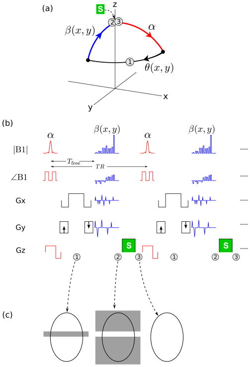
The proposed imaging principle is illustrated in Fig. 1. Just as in bSSFP or SPGR, a simple sliceselective tip-down pulse α is first played out, and the signal is acquired during a free precession interval of duration Tfree, during which the spin precesses in the transverse plane with an angle θ(x, y) = ω(x, y)Tfree, where ω(x, y) = γB0 is the local off-resonance. After data readout, spins within the desired imaging slice are tipped back toward the longitudinal axis (mz) by a spatially-tailored tip-up pulse β(x, y). Note that the tip-up pulse can in principle be designed for arbitrary phase accrual θ(x, y), provided that θ(x, y) is sufficiently smooth relative to the spatial frequency content of the tailored tip-up pulse. In particular, θ(x, y) need not be small. Since the tip-up pulse is non-slice-selective, spins outside the desired imaging slice will be excited (Fig. 1(c)). This out-of-slice signal is removed using spoiling, i.e. by inserting a gradient spoiler S after the tip-up pulse, and cycling the RF phase, for example using a linear phase increment of 117° × n, where n is the RF shot number (10). Note that the tip-down and tip-up pulses have a common RF phase offset.
Figure 1.
Proposed STFR imaging principle. (a) Steady-state spin path for a single spin isochromat. (b) Proposed STFR implementation, illustrative 2D imaging example. (c) Desired transverse magnetization pattern at the time-points labeled “1”, “2”, and “3” in (a) and (b), for an axial slice. At time-point “1”, only the imaging slice is excited and hence imaged (left). Immediately after the non-slice-selective tip-up pulse (“2”), spins within the imaging slice have been realigned with the z-axis, while out-of-slice spins have been excited (middle). After the gradient spoiler S (time-point “3”), no transverse magnetization remains (right). TR-to-TR signal coherence pathways for out-of-slice spins are suppressed using RF-spoiling.
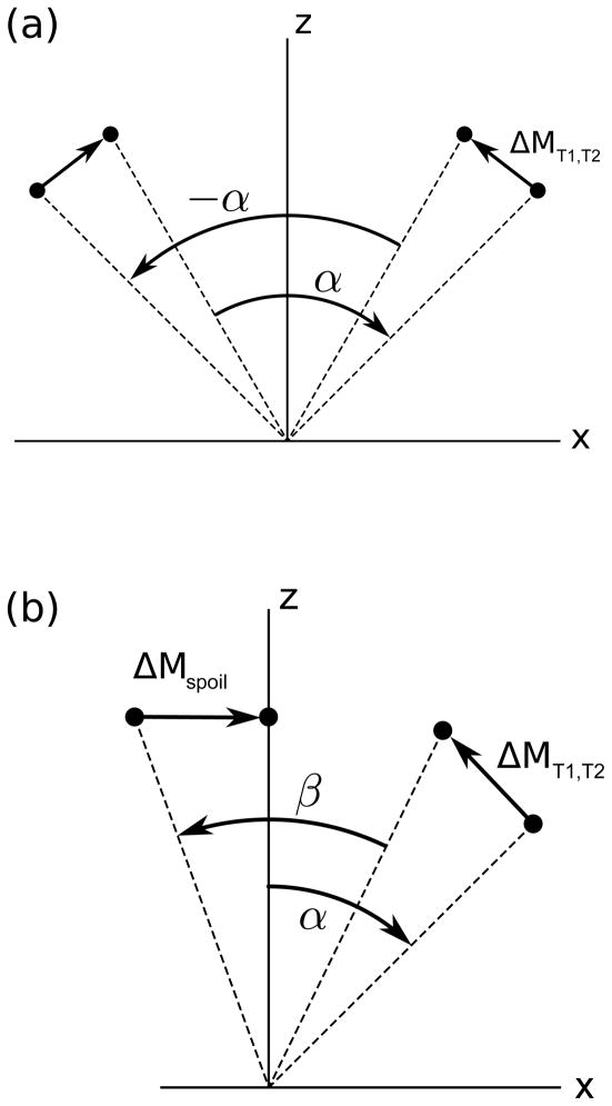
To make the distinction between bSSFP and STFR clear, Figure 2 shows the steady-state spin paths in the xz-plane for a spin with zero off-resonance.
Figure 2.
Graphical illustration of the steady-state spin paths for (a) bSSFP and (b) the proposed STFR method, for an on-resonance spin (not drawn to scale). In bSSFP (a), the T1 recovery and T2 decay that occurs between RF pulses is perfectly balanced between alternating RF shots. In STFR (b), the T1 and T2 decay that occurs after the tip-down pulse α, combined with the effect of the spoiler following the tip-up pulse β, act to bring the longitudinal magnetization back to the same starting point prior to each tip-down pulse.
Signal theory under ideal conditions
To obtain a simple qualitative description of the STFR signal, we assume that the RF pulse duration is negligible. Clearly, this assumption is not met in general, since the RF pulse duration depends on the details of the tip-up pulse design. Nevertheless, we will show that the qualitative predictions based on this assumption is confirmed in-vivo. With this assumption, the steady-state transverse STFR signal M⊥ immediately after the tip-down pulse can be shown to be:
| [1] |
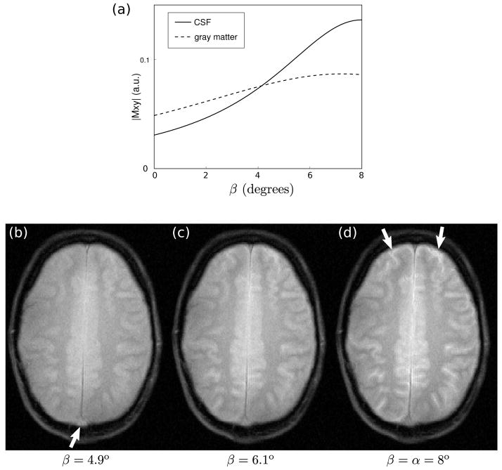
Here Ts is the delay needed for the gradient spoiler, which is played out immediately after the tip-up pulse. Equation [1] predicts that the STFR signal contains both T1 and T2 weighting. Furthermore, in the limits of TR≪T2 and Ts = 0, and assuming β = α, it can be shown that the STFR signal is equal to the bSSFP on-resonance signal with flip angle 2α. We therefore expect STFR images to produce similar tissue contrast as bSSFP. Note that in the limits β = 0 and Ts = 0, Eq. [1] is identical to the Ernst formula with flip angle α. In addition, Eq. [1] predicts that the signal from cerebrospinal fluid (CSF) is high when β(x, y) = α, but drops off rapidly with decreasing β(x, y) (due to the very long T2 of CSF). This is illustrated in Fig. 9(a), which shows the calculated signal for CSF and gray matter based on Eq. [1], assuming T1/T2 = 4000/2000 msec and 1300/80 msec for CSF and gray matter, respectively. 1. This suggests that hyper-enhancement of CSF may be avoided by reducing β(x, y) slightly.
Figure 9.
Effect of varying the tip-up angle (β) on in-vivo image contrast. (a) Calculated steady-state signal for CSF and gray matter at 3T, using Eq. [1] (Tfree/TR = 8/11 msec, α=8°). (b–d) In-vivo results, using a blipped tip-up pulse (as in Fig. 1(b)), with TR=11.1 ms. The same slice was imaged three times, and the amplitude of the tip-up pulse β(x, y) was set to (b) 4.9°, (c) 6.1°, and (d) 8°, respectively. The tip-down pulse α was held fixed at 8°. Note the behavior of CSF (arrows in (d)) and through-plane vessel signal (arrow in (b)).
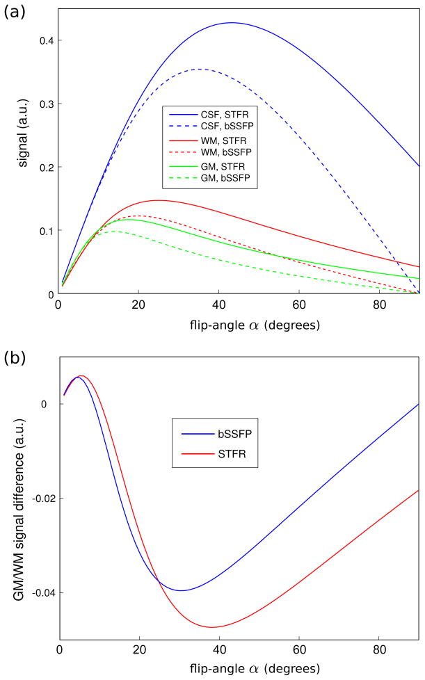
Figure 3 shows the predicted signal for white matter, gray matter, and CSF, for flip angles α ranging from 0 to 90°. These plots show that STFR is expected to produce similar signal and tissue contrast as bSSFP.
Figure 3.
Predicted tissue signal for STFR using Eq. [1] (Tfree/TR = 8/12 msec, α = β), and for bSSFP. Note that the bSSFP curves were calculated using a flip angle of 2α. (a) Theory predicts that STFR produces high CSF signal for all flip angles, similar to bSSFP. (b) Predicted gray/white matter contrast for STFR and bSSFP. STFR and bSSFP are expected to produce similar gray/white matter contrast.
Effect of an imperfect tip-up pulse
In practice, the phase of the tip-up pulse will not match the local spin phase exactly, which will reduce the observed signal relative to the ideal theoretical value expressed in Eq. [1]. We propose to use Eq. [1] to describe the STFR signal even in the case of such a phase mismatch, except that T2 should be replaced by an “effective” transverse relaxation rate T2eff, defined by the relation e−Tfree/T2 cos(Δθ) ≡ e−Tfree/T2eff, or
| [2] |
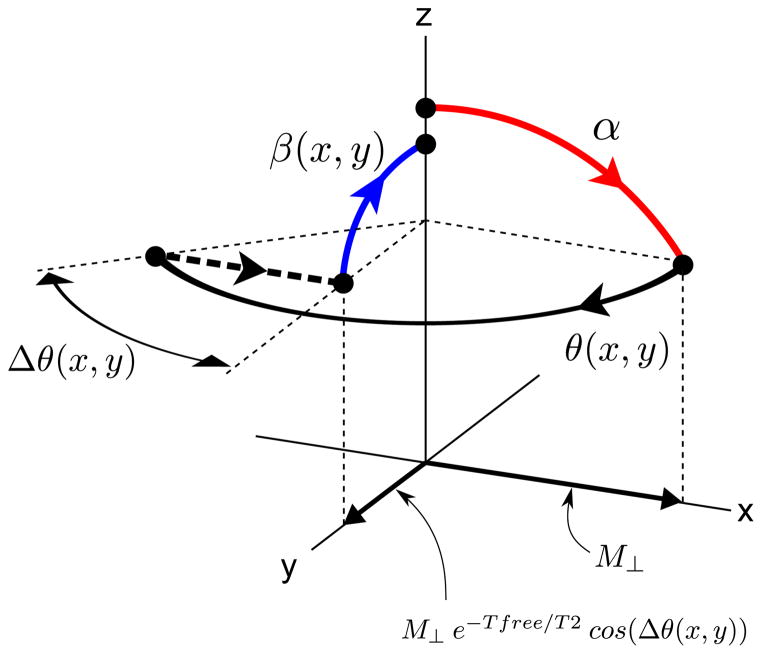
where Δθ is the phase mismatch between the target phase θ(x, y) and the phase of the tip-up pulse. In essence, we are treating the phase mismatch Δθ as an additional “T2-like” transverse relaxation factor. Specifically, we assume that the transverse magnetization vector component M⊥ is reduced by a factor e−Tfree/T2 cos(Δθ), as illustrated in Fig. 4.
Figure 4.
Graphical illustration of the rationale behind Eq. [2]. Immediately after the tip-down pulse α, the transverse signal component has magnitude M⊥ and is aligned with the axis of the tip-down pulse (x). During the free precession interval, the transverse component is reduced to M⊥ e−Tfree/T2 (not indicated in the figure). We then assume that there is a mismatch Δθ between the transverse spin phase and the phase of the tip-up pulse. As a result, only the component of M⊥ e−Tfree/T2 along the axis of the tip-up pulse, i.e. M⊥ e−Tfree/T2 cos(Δθ), is tipped back up. Equation [2] is obtained by defining an effective transverse relaxation rate T2eff defined by the relation M⊥ e−Tfree/T2 cos(Δθ) ≡ M⊥ e−Tfree/T2eff.
METHODS
Experimental validation of Eqs. [1] and [2]
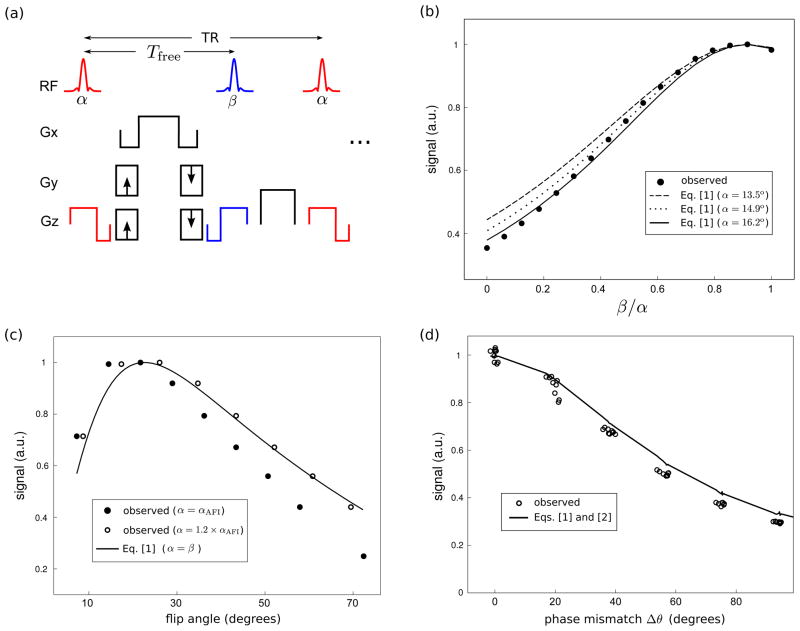
To validate Eqs. [1] and [2], we performed three imaging experiments in a uniform gelatin ball phantom. The pulse sequence consisted of independently-controlled tip-down and tip-up RF segments, and a conventional Cartesian (spin-warp) readout with balanced gradients (Fig. 5(a)). The tip-down pulse was a slice-selective sinc or Shinnar-Le Roux (13) pulse with time-bandwidth product 4. The tip-up pulse was identical to the tip-down pulse, except time-reversed. The flip angle α was measured using AFI (14), with TR1/TR2 = 10/110 msec. The off-resonance map was measured using SPGR with TR=10 msec and echo times of 3 and 5 msec. The acquisition bandwidth was ±31.25 kHz. T1 and T2 were measured using inversion recovery and spin-echo, respectively (T1/T2 = 520/50 msec).
Figure 5.
Experimental validation of Eqs. [1] and [2]. (a) Pulse sequence diagram. The tip-up pulse is identical to the tip-down pulse, except time-reversed. (b) Steady-state signal as a function of tip-up angle β, with the tip-down flip angle α held constant (Tfree/TR = 4.3/7.0 msec). (c) Steady-state signal as a function of flip angle (Tfree/TR = 10.0/15.0 msec). (d) Steady-state signal as a function of phase mismatch Δθ between the phase of the tip-up pulse and the spin phase (Tfree/TR = 9.3/12.0 msec).
The three different experiments were conducted on different days. In the first experiment, we varied the magnitude of the tip-up pulse β from 0 to α, with α held fixed. The middle slice from a 64×64×8 3D acquisition with field-of-view (FOV) 24×24×3 cm3 was used in the analysis. The tip-down pulse was of duration 0.5 ms (not including slice-select gradients), and slab thickness 10 mm. In each resulting image, the mean signal within a region-of-interest (ROI) with near-zero off-resonance was calculated. The resulting signal curve was compared with the calculated values from Eq. [1] (Tfree/TR = 4.3/7.0 msec; T1=520 msec, T2eff=T2=50 msec).
In the second experiment, we varied the flip angle from approximately 10 to 70 degrees, and recorded the mean signal within an ROI with near-zero off-resonance. The resulting signal curve was compared with the calculated values from Eq. [1] (Tfree/TR = 10.0/15.0 msec; T1=520 msec, T2eff=T2=50 msec). The acquisition was 2D with 24×24 cm2 FOV, 64×64 matrix, and a tip-down pulse of duration 2 ms and slice thickness 5 mm.
In the third experiment, we introduced a linear off-resonance across the phantom by adjusting the gradient shim. We then acquired one STFR image, with α = β. The middle slice from a 64×64×8 3D acquisition with FOV 24×24×3 cm3 was used in the analysis. The same tip-down pulse as in the first experiment was used. We selected an ROI consisting of a rectangular region near the center of the phantom, and for each pixel within this ROI, the phase mismatch Δθ, flip angle α, and signal was recorded. The observed signal was plotted against Δθ, and compared with the calculated values from Eq. [1], with Tfree/TR = 9.3/12.0 msec, T1=520 msec, and T2eff given by Eq. [2].
2D RF pulse design
The tip-up pulse β (x, y) is spatially tailored, and hence requires multi-dimensional RF pulse design principles and/or a parallel transmit array. We consider in this work a small-tip design with two different excitation k-space trajectories: “blipped” and spiral (15, 16). A small-tip design is appropriate for brain imaging using the proposed method, since the optimal flip angle for gray matter is only 16°, one-half of the bSSFP optimal flip angle.
Blipped pulses, which consist of a train of weighted sub-pulses (e.g. slice-selective sincs), are relatively insensitive to gradient system imperfections such as unknown gradient delays or eddy currents. Blipped pulses are therefore ideal for assessing the intrinsic image contrast of the proposed STFR sequence. We employ the RF pulse design algorithm in (17), which uses a “greedy” search to obtain the pulse weights that best match the desired excitation pattern. In our previous implementation, each blip consisted of a slice-selective sinc pulse (a “spoke”) of approximately 0.5 ms duration. With the proposed implementation, the tip-up pulse is non-selective, and hence the sinc pulses can be replaced with fast hard pulses. In this article, all tip-up pulses were implemented with 10 rectangular “blips”, each lasting only 40 μs. We found empirically that this pulse train can achieve a maximum flip angle of just under 20° without violating the peak B1 constraints of our system (0.25 Gauss). Note that no gradients are applied during RF transmission. The hard pulses are separated by x and y gradient “blips” that traverse excitation kx-ky space. Note that this is different from an echo-planar trajectory, where time-varying RF and gradient fields are transmitted simultaneously. The total tip-up pulse duration, including all gradients, was 1.4–1.6 ms. A corresponding pulse using slice-selective sinc pulses would require a pulse duration of 6.5 ms.
Spiral tip-up pulses were designed using the small-tip design method in (18), implemented with the IRT Matlab toolbox (Jeff Fessler, University of Michigan). The advantage of spiral tip-up pulses is that they sample excitation k-space much more efficiently than blipped designs, and are therefore expected to produce much better excitation accuracy (i.e. reduced Δθ) for a given total RF pulse duration. The disadvantage of spirals is that they are very sensitive to system imperfections. Since the exact gradient delays with respect to the RF waveform are generally not known, the spiral STFR acquisitions were repeated with different applied gradient delays. The RF waveform duration was approximately 2.3 msec, excluding the gradient prewinder.
In both designs, phase accrual during RF transmission was accounted for. We found in simulation that this was essential for accurate tip-up performance (not shown).
Note that we designed β (x, y) by first creating an intermediate tip-down pulse using eiθ(x,y) as the target excitation pattern, where
| [3] |
is the expected spin precession angle based on the measured local off-resonance ω(x, y) in a 2D slice. In the design of the intermediate tip-down pulse, the off-resonance was set to the negative of the observed B0 map. The resulting tip-down pulse was then used to obtain the final tip-up pulse by traversing excitation k-space in reverse, effectively “undoing” the excitation created by the intermediate tip-down pulse. This procedure was the same for both blipped and spiral tip-up pulses.
Phantom imaging experiments
All imaging experiments were performed on a GE Signa 3T scanner using a commercial quadrature headcoil. A 3D readout was chosen in order to eliminate any possible influence of imperfect slice-profile on the final images. The tip-down pulse was a slice-selective sinc pulse of time-bandwidth product 4, duration 0.5 ms (not including slice-select gradients), and slab thickness 10 mm. We measured the flip angle experimentally by acquiring multiple SPGR images at different TR in the phantom, and fitting to the Ernst formula (not shown). The observed tip-down angle of α = 8° was used because it is approximately equal to the Ernst angle for brain tissue imaging at 3T, and should therefore give maximum SPGR signal. Note that this is less than the optimal flip angle for gray matter imaging using bSSFP or STFR at 3T, which is approximately 32° and 16°, respectively. For the SPGR and STFR acquisitions, the gradient spoiler S after the tip-up pulse consisted of a trapezoidal gradient along z. Off-resonance maps were acquired with a 3D SPGR sequence (64×64×8 matrix; FOV 24×24×3 cm; flip angle 8°; TR=10 ms; acquisition bandwidth ± 125 kHz), and only the central 2D slice was used in the design of the tailored tip-up pulse.
Phantom observations were made in the same uniform gelatin ball phantom used in the theory validation experiments. (Tfree = 5.7 ms; 64×64×8 matrix; FOV 24×24×3 cm; tip-down angle α = 8°; TR/TE=9/2 ms; acquisition bandwidth ±125 kHz). We imaged the residual transverse magnetization after the tip-up pulse, in order to verify that the tip-up pulse brings the spins within the desired imaging slice back toward the longitudinal axis. We also performed SPGR, bSSFP, and STFR acquisitions with the same tip-down angle α, to verify that STFR produces enhanced signal compared with SPGR.
Human volunteer imaging
One healthy human volunteer was imaged in three different sessions using the same pulse sequence as in the phantom imaging experiments (Table 1). In each session, we acquired SPGR, bSSFP, and STFR images, to compare image contrast. Both blipped (Session 1) and spiral (Sessions 2–3) tip-up pulses were tested, using both 3D (Sessions 1–2) and 2D (Session 3) imaging. The 2D imaging session was added to assess the practicability of STFR brain imaging of a thin 2D slice, using the theoretically optimal flip angle of 16° (and 32° for bSSFP) for gray matter at 3T. The 3D imaging sessions used TE=3.7 ms, Tfree =6.8 ms, acquisition bandwidth ±31.25 kHz, and the same tip-down pulse as in the phantom experiments (sinc, 8°). The 2D imaging session used TE=4.4 ms, Tfree =7.4 ms, acquisition bandwidth ±31.25 kHz, and a 4 mm slice-selective Shinnar-Le Roux pulse of time-bandwidth product 4 (13). In the blipped acquisition (Session 1), we varied the magnitude of the tip-up pulse β, in order to investigate its effect on image contrast. In each case the minimum achievable TR was used, except where noted otherwise.
Table 1.
Summary of phantom and human imaging experiments.
| tip-down angle α | readout | tip-up pulse | |
|---|---|---|---|
| Phantom | 8° | 3D | blipped |
| Session 1 | 8° | 3D | blipped |
| Session 2 | 8° | 3D | spiral |
| Session 3 | 16/32° | 2D | spiral |
RESULTS
Experimental validation of Eqs. [1] and [2]
Figure 5(b) shows the dependence of the steady-state signal on tip-up angle β, for fixed tip-down angle α, and for zero phase mismatch (Δθ=0). Since the actual flip angle may deviate from the AFI measurement, we calculated three different curves, corresponding to α = 13.5° (the mean observed value), 14.9°, and 16.2°. The latter value, which was obtained by multiplying the measured flip angle by 1.2, produces a reasonably good fit to the observed signal curve.
Figure 5(c) shows the calculated and observed steady-state signal as a function of flip angle, with β = α. Since the actual flip angle α may deviate from the AFI measurement αAFI, we calculated two different experimental curves, corresponding to α = αAFI and α= 1.2 × αAFI. Measurements were made within voxels that were close to on-resonance, such that Δθ ≃ 0. Again, the observed curve is in reasonable agreement with the theoretical curve calculated from Eq. [1], particularly for α= 1.2 × αAFI. We see that the acquired signal peaks at a low flip angle.
Figure 5(d) shows the calculated and observed steady-state signal as a function of phase mismatch Δθ for β = α. The calculation was based on the measured flip angle in each pixel (using AFI), multiplied by 1.2. Again, we generally observe good agreement between observation and theory.
Figure 5 shows that Eqs. [1–2] provide a reasonably accurate description of the STFR signal. For gray matter at 3T, these equations predict that it is necessary to achieve tip-up phase accuracy of approximately ±40° in order to avoid signal loss of more than 50%.
Phantom observations
Figure 6(a) shows the residual transverse magnetization immediately after the tip-up pulse (time-point “2” in Fig. 1). The signal in the desired imaging region (center slice) is significantly suppressed compared with neighboring slices, indicating that the tip-up pulse aligns most of the magnetization with the z axis, as desired.
Figure 6.
Ability of the tip-up pulse to align magnetization within the imaging slice along the longitudinal axis. (a) Residual transverse magnetization immediately after the tip-up pulse (time-point “2” in Fig. 1), phantom observations. Seven slices are shown. The signal in the desired imaging region (center slice) is significantly suppressed compared with neighboring slices, indicating that the tip-up pulse aligns most of the magnetization with the longitudinal axis, as desired. (b) Predicted magnetization for the center slice, Bloch simulation results. Simulated and observed residual magnetization patterns are in good agreement.
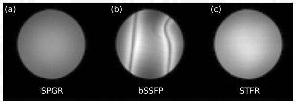
Figure 7 shows matched SPGR, bSSFP, and STFR images, and illustrates that STFR can produce enhanced signal compared to a fully spoiled acquisition (SPGR). Note the absence of banding artifacts in the STFR image.
Figure 7.
Comparison of (a) SPGR, (b) bSSFP, and (c) STFR acquisitions in a uniform gel phantom. In the STFR acquisition (c), the signal was acquired at time-point “1” in Fig. 1. STFR produces higher signal than SPGR, and no banding artifacts.
Human volunteer observations, blipped tip-up pulse
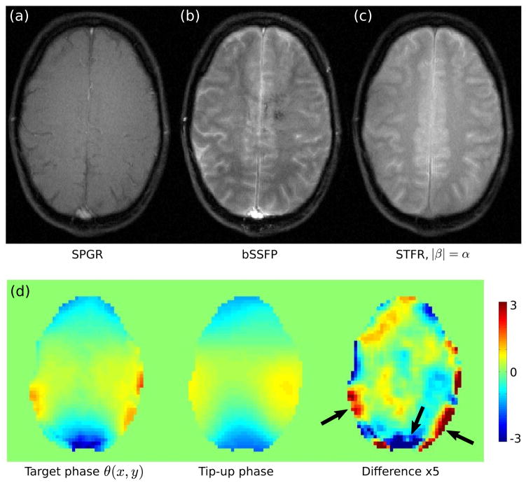
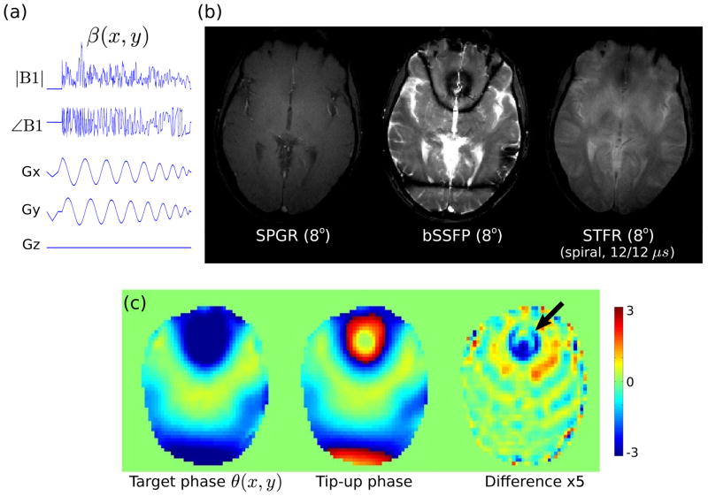
Figure 8 shows brain imaging results using SPGR, bSSFP, and the proposed STFR method. SPGR produces relatively low tissue signal, dark CSF, and bright vessel signal due to in-flow enhancement. Balanced SSFP produces bright CSF in accordance with its high T2/T1 ratio and high vessel signal, both of which are generally undesirable. However, the gray/white matter contrast in bSSFP is excellent, which makes this sequence useful for T2 lesion imaging, for example. The origin of the dark u-shaped band in Fig. 8(b) is unclear, but may be due to aliasing from spins outside of the imaging slice that reside in the so-called bSSFP “transition band”. STFR (Fig. 8(c)) produces excellent gray/white matter contrast similar to bSSFP, indicating that the tip-up pulse introduces T2-weighting into the steady-state magnetization, as expected. However, we observe some signal shading across the image, in the areas indicated by the arrows in Fig. 8(d). These regions generally coincide with regions that have high phase mismatch between the spin phase and the phase of the tip-up pulse (> π/5), as expected. Note that the phase difference in some pixels exceed π/5, and therefore appear truncated in the phase-difference image in (c).
Figure 8.
Comparison of (a) SPGR (TR=10.9 ms), (b) bSSFP (TR=9.5 ms), and (c) the proposed STFR sequence (|β|= α, TR=11.1 ms). The tip-down excitation pulse was the same for all acquisitions (α = 8°). In (c), the tip-up pulse consisted of a train of 10 blips, similar to the pulse sequence shown in Fig. 1(b). SPGR (a) produces relatively low tissue signal, consistently dark CSF, and bright vessel signal due to in-flow enhancement. Balanced SSFP (b) produces bright CSF in accordance with its high T2/T1 ratio, and high vessel signal. STFR produces good gray/white matter contrast similar to bSSFP, indicating that the tip-up pulse introduces T2-weighting. (d) Comparison of target phase θ (x, y) (left), and the simulated phase of the tip-up pulse (units of radians). The phase of the tip-up pulse is in good agreement with the target phase, as desired.
Figure 9 shows the effect of varying the tip-up angle β on image contrast. For the highest value of β (8°, Fig. 9(d)), the anterior CSF signal is bright, just as in bSSFP. As β decreases, we observe that the gray and white matter signals also decrease, and that the gray/white matter contrast decreases. This behavior is in qualitative agreement with theory. We also observe that the anterior CSF signal decreases relatively rapidly with decreasing β also in accordance with theory (Fig. 9(a)). Finally, we observe that the vessel signal increases with decreasing β, indicating increased in-flow enhancement (19). In other words, the image contrast becomes increasingly SPGR-like with decreasing β.
Human volunteer observations, spiral tip-up pulse
Figure 10 shows the results of 3D STFR imaging using a 2D spiral tip-up pulse tailored to the central slice. STFR fails to recover the signal in the frontal sinus, indicating that the B0 inhomogeneity is too large for this particular spiral tip-up pulse. In particular, Fig. 10(c) shows that the phase mismatch in the frontal sinus exceeds π/5 (≃ 40°), and pixels in this region therefore appear truncated in the phase-difference image in (c). Furthermore, the magnitude of the tip-up pulse also shows relatively large deviations in this region (not shown), which may further contribute to the signal loss. Nevertheless, most of the image exhibits good tissue contrast. However, CSF appears somewhat suppressed in the STFR image compared to bSSFP. This is unexpected, since our theory predicts relatively bright CSF for both bSSFP and STFR, independent of flip angle (Fig. 3(a)). The source of the low CSF signal in Fig. 10(c) is currently unknown, but may be due to low tip-up angle β (see e.g. Fig. 9(a)).
Figure 10.
Feasibility of STFR imaging using a tip-up pulse with a spiral excitation k-space trajectory of duration 2.3 msec. (a) Tip-up pulse sequence diagram. (b) Comparison of SPGR, bSSFP, and STFR acquisitions, using the same tip-down angle α (8°) and TR (11.8 ms). Note that the TR of bSSFP was slightly longer than strictly necessary, which reduces the spacing between the bands somewhat. As in Figs. 8–9, the middle slice from a 3D acquisition is shown. The numbers below the STFR image indicate the applied x/y gradient delays in microseconds. (c) The target phase θ(x, y) and the (simulated) phase of the tip-up pulse are in good agreement, except near the frontal sinus.
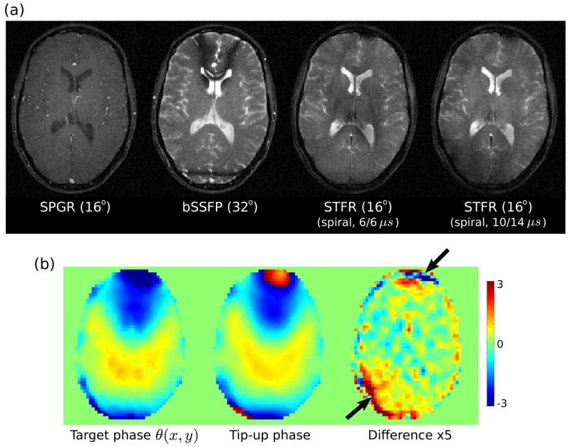
Figure 11 shows the results of 2D STFR imaging using a similar tip-up pulse as that shown in Fig. 10(a). These results are in good overall agreement with the 3D imaging results. In particular, we observe bright CSF and good gray/white matter contrast, except in regions of relatively high phase mismatch (arrows in Fig. 11(b)).
Figure 11.
Feasibility of 2D STFR imaging with a spiral tip-up pulse, using the theoretically optimal flip angle of 16° for gray matter at 3T. The tip-up pulse was similar to that shown in Fig. 10(a). (a) Comparison of SPGR (TR=14.2 ms), bSSFP (TR=9.9 ms), and STFR (TR=14.2 ms) acquisitions. (b) The target phase θ(x, y) and the (simulated) phase of the tip-up pulse are in good agreement, except in the regions indicated by the arrows.
DISCUSSION
The proposed method relies on the ability of the tip-up pulse to align the magnetization with the longitudinal axis. Our simplified STFR signal model, expressed in Eqs. [1–2], predicts that the phase of the tip-up pulse must be within a few tens of degrees in order to avoid significant signal loss. Our in-vivo observations, using both blipped and spiral tip-up pulses, confirm this prediction. In particular, we have observed that a phase mismatch of approximately π/5, or approximately 40°, produces a noticeable loss in image contrast. Generally speaking, for a given RF pulse duration and excitation k-space trajectory, the accuracy of the tip-up pulse decreases with increasing B0 inhomogeneity. Similarly, for a given phase accrual θ(x, y) and a given excitation k-space trajectory, the accuracy of the tip-up pulse decreases with decreasing RF pulse duration. For example, we have found that using a blipped excitation k-space trajectory of total duration 1.5 ms, it is not possible to design accurate tip-up pulses in axial slices at the level of the sinuses. We anticipate that the preferred implementation of the proposed method will use spiral or other echo-planar excitation k-space trajectories, which offer improved performance in theory, but also introduce practical challenges such as sensitivity to eddy currents and gradient delays.
The tip-up pulse performance can be improved by reducing the free precession time Tfree. In our current implementation using a ±31.25 kHz acquisition bandwidth, the total duration of the frequency-encode gradients was approximately 6 ms, including the defocusing and refocusing gradient lobes. Alternative readout trajectories such as partial Fourier and radial can reduce Tfree, and hence improve the homogeneity of the target phase pattern used in the tip-up pulse design (Eq. [3]). A similar strategy can in principle be used to reduce the TR in bSSFP, although we anticipate that bSSFP may be more sensitive to the changing eddy currents caused by a radial acquisition scheme. In addition, it may be possible to reduce the time from the peak to the end of the tip-down pulse, e.g. using VERSE RF pulse design (20).
In the future, we anticipate that the proposed implementation will benefit directly from hardware improvements in two areas: (1) parallel excitation, which refers to the use of multiple independently controlled transmission coils, and (2) high-order gradient shim systems. Parallel excitation allows improved pulse performance or reduced pulse length, in a manner analogous to parallel imaging. The goal of high-order gradient shimming is to reduce the static B0 inhomogeneity, which makes the target excitation phase pattern smoother and hence easier to produce.
We have observed that CSF is suppressed when the tip-up angle β is less than the tip-down angle α, and that through-plane vessel signal is also suppressed due to partial saturation of out-of-slice spins. These observations suggest that steady-state T2-weighted imaging with intrinsic CSF suppression and lack of in-flow enhancement may be possible using the proposed sequence, which could be useful as an alternative to FLAIR spin-echo or FLAIR bSSFP imaging of T2 lesions in e.g. multiple sclerosis patients.
Fat resonates at a frequency offset of −440 Hz compared to water protons at 3T, and the tip-up pulses designed from water-only B0 maps will therefore not be appropriate for fat. As a result, the signal level in local fat deposits is unpredictable and may vary spatially. It may be possible to account for fat explicitly in the RF design algorithm, with the goal of suppressing fat uniformly across the slice. Alternatively, it may be possible to incorporate a fat suppression pulse, analogous to the fat-saturated bSSFP sequence in (21).
We do not yet know whether the discrepancies between the bSSFP images and the spiral STFR acquisitions observed in Figs. 10 and 11 can be fully explained by the transverse phase mismatch, or whether other sources of error such as spiral gradient imperfections (i.e. trajectory errors during tipup RF transmission) or imperfect spoiling also play a significant role. Further studies are needed to address this issue.
Figure 5 shows that the proposed STFR signal theory, expressed in Eqs. [1] and [2], provides a good description of the STFR signal under ideal imaging conditions. The discrepancies between theory and observation in Fig. 5 may be due to several possible sources, including non-ideal slice profile, inaccurate flip angle measurements, or intrinsic errors in our signal model (e.g. due to the simplifying assumption that the tip-up pulse is instantaneous).
CONCLUSIONS
We have presented a proof-of-principle demonstration of STFR imaging with 2-dimensional tailored RF pulses, and have shown that brain imaging is feasible using a standard head coil and a short tip-up pulse (~2 ms). The resulting images show excellent gray/white matter contrast, and point to the possibility of rapid steady-state T2/T1-weighted imaging with intrinsic suppression of CSF, vessel signal, and off-resonance artifacts. The performance of the proposed method depends on the accuracy of the tip-up pulse, and in the future we expect STFR imaging to benefit significantly from parallel excitation hardware and high-order gradient shim systems.
Acknowledgments
Grant Sponsors: National Institutes of Health (R01NS058576, R21EB012674)
Footnotes
References
- 1.Heilman JA, Derakhshan JJ, Riffe MJ, Gudino N, Tkach J, Flask CA, Duerk JL, Griswold MA. B0 and B1 correction using the inherent degrees of freedom of a multi-channel transmit array. Proc., ISMRM, 17th Annual Meeting; Honolulu. 2009. p. 251. [Google Scholar]
- 2.Nielsen JF, Yoon D, Noll DC. Suppression of banding and transient signal oscillations in balanced SSFP using a spoiled RF pre-phasing approach. Proc., ISMRM, 18th Annual Meeting; Stockholm. 2010. [Google Scholar]
- 3.Nielsen JF, Yoon D, Hollingsworth NA, Moody KL, McDougall MP, Wright SM, Noll DC. Joint optimization of tip-down and tip-up rf pulses in small-tip (non-spin-echo) fast recovery imaging. Proc., ISMRM, 19th Annual Meeting; Montreal. 2011. p. 209. [Google Scholar]
- 4.Scheffler K, Lehnhardt S. Principles and applications of balanced SSFP techniques. Eur Radiol. 2003;13:2409–2418. doi: 10.1007/s00330-003-1957-x. [DOI] [PubMed] [Google Scholar]
- 5.Bangerter NK, Hargreaves BA, Vasanawala SS, Pauly JM, Gold GE, Nishimura DG. Analysis of multiple-acquisition SSFP. Magn Reson Med. 2004;51:1038–1047. doi: 10.1002/mrm.20052. [DOI] [PubMed] [Google Scholar]
- 6.Overall WR, Nishimura DG, Hu BS. Steady-state sequence synthesis and its application to efficient fat-suppressed imaging. Magn Reson Med. 2003;50:550–559. doi: 10.1002/mrm.10542. [DOI] [PubMed] [Google Scholar]
- 7.Cukur T, Nishimura DG. Multiple repetition time balanced steady-state free precession imaging. Magn Reson Med. 2009;62:193–204. doi: 10.1002/mrm.21990. [DOI] [PMC free article] [PubMed] [Google Scholar]
- 8.Nayak KS, Lee HL, Hargreaves BA, Hu BS. Wideband SSFP: alternating repetition time balanced steady state free precession with increased band spacing. Magn Reson Med. 2007;58:931–938. doi: 10.1002/mrm.21296. [DOI] [PubMed] [Google Scholar]
- 9.Leupold J, Hennig J, Scheffler K. Alternating repetition time balanced steady state free precession. Magn Reson Med. 2006;55:557–565. doi: 10.1002/mrm.20790. [DOI] [PubMed] [Google Scholar]
- 10.Zur Y, Wood ML, Neuringer LJ. Spoiling of transverse magnetization in steady-state sequences. Magn Reson Med. 1991;21:251–263. doi: 10.1002/mrm.1910210210. [DOI] [PubMed] [Google Scholar]
- 11.Hsu JJ, Glover GH, Zaharchuk G. Optimizing saturation-recovery measurements of the longitudinal relaxation rate under time constraints. Magn Reson Med. 2009;62:1202–1210. doi: 10.1002/mrm.22111. [DOI] [PubMed] [Google Scholar]
- 12.Wong EC, Liu TT, Luh WM, Frank LR, Buxton RB. T1 and T2 selective method for improved SNR in CSF-attenuated imaging: T2-FLAIR. Magn Reson Med. 2001;45:529–532. doi: 10.1002/1522-2594(200103)45:3<529::aid-mrm1071>3.0.co;2-l. [DOI] [PubMed] [Google Scholar]
- 13.Pauly JM, Le Roux P, Nishimura DG, Macovski A. Parameter relations for the Shinnar-Le Roux selective excitation pulse design algorithm. IEEE Trans Med Imaging. 1991;10:53–65. doi: 10.1109/42.75611. [DOI] [PubMed] [Google Scholar]
- 14.Yarnykh VL. Actual flip-angle imaging in the pulsed steady state: a method for rapid three-dimensional mapping of the transmitted radiofrequency field. Magn Reson Med. 2007;57:192–200. doi: 10.1002/mrm.21120. [DOI] [PubMed] [Google Scholar]
- 15.Zhang Z, Yip CY, Grissom W, Noll DC, Boada FE, Stenger VA. Reduction of transmitter B1 inhomogeneity with transmit SENSE slice-select pulses. Magn Reson Med. 2007;57:842–847. doi: 10.1002/mrm.21221. [DOI] [PMC free article] [PubMed] [Google Scholar]
- 16.Pauly JM, Nishimura DG, Macovski A. A k-space analysis of small tip excitation. J Magn Reson. 1989;81:43–56. doi: 10.1016/j.jmr.2011.08.008. [DOI] [PubMed] [Google Scholar]
- 17.Yoon D, Fessler JA, Gilbert AC, Noll DC. Simultaneous signal loss correction from B1 and B0 inhomogeneity in BOLD fMRI with parallel excitation. Proc., ISMRM 3rd International Workshop on Parallel MRI; Santa Cruz. 2009. p. 38. [Google Scholar]
- 18.Yip CY, Fessler JA, Noll DC. Iterative RF pulse design for multidimensional, small-tip-angle selective excitation. Magn Reson Med. 2005;54:908–917. doi: 10.1002/mrm.20631. [DOI] [PubMed] [Google Scholar]
- 19.Han M, Hargreaves BA. Reduction of flow artifacts by using partial saturation in RF-spoiled gradient-echo imaging. Magn Reson Med. 2011;65:1326–1334. doi: 10.1002/mrm.22729. [DOI] [PMC free article] [PubMed] [Google Scholar]
- 20.Hargreaves BA, Cunningham CH, Nishimura DG, Conolly SM. Time-optimal VERSE excitation for 3d balanced SSFP imaging. Proc., ISMRM, 12th Annual Meeting; Kyoto. 2004. p. 260. [Google Scholar]
- 21.Scheffler K, Heid O, Hennig J. Magnetization preparation during the steady state: fat-saturated 3D trueFISP. Magn Reson Med. 2001;45:1075–1080. doi: 10.1002/mrm.1142. [DOI] [PubMed] [Google Scholar]


