

Abstract
An 8-channel receive coil array was constructed and implanted adjacent to the skull in a male rhesus monkey in order to improve the sensitivity of (functional) brain imaging. The permanent implant was part of an acrylic headpost assembly and only the coil element loop wires were implanted. The tuning, matching, and preamplifier circuitry was connected via a removable external assembly. Signal-to-noise ratio (SNR) and noise amplification for parallel imaging were compared to a single-, 4-, and 8-channel external receive-only coil routinely used for macaque fMRI. In vivo measurements showed significantly improved SNR within the brain for the implanted versus the external coils. Within a region-of-interest covering the cerebral cortex, we observed a 5.4-, 3.6-fold, and 3.4-fold increase in SNR compared to the external single-, 4-, and 8-channel coil, respectively. In the center of the brain, the implanted array maintained a 2.4×, 2.5×, and 2.1× higher SNR, respectively compared to the external coils. The array performance was evaluated for anatomical, diffusion tensor and functional brain imaging. This study suggests that a stable implanted phased-array coil can be used in macaque MRI to substantially increase the spatial resolution for anatomical, diffusion tensor, and functional imaging.
Keywords: fMRI, macaque, parallel imaging, implanted coil, high resolution
1. Introduction
The awake macaque monkey is an important animal model in neuroscience for detailed invasive studies of perceptual and cognitive processes. During the last decade, MR image techniques such as fMRI and DTI have proven to be highly valuable for studying cognitive processing and anatomy in these monkeys (Adluru et al., 2012; Arcaro et al., 2011; Bell et al., 2009; Disbrow et al., 2000; Logothetis et al., 1999; Logothetis et al., 2001; Makris et al., 2007; Matsui et al., 2011; Moeller et al., 2008; Stefanacci et al., 1998; Tsao et al., 2003a; Vanduffel et al., 2001). Compared to human MRI, additional technical challenges have to be addressed for monkey MRI (Goense et al., 2010b). Firstly, because of the smaller head size of the macaque monkey a higher spatial resolution is required to reveal similar anatomical detail as in the human. This means that the signal-to-noise ratio (SNR) per voxel is inherently lower for monkey MRI than for human MRI. While smaller coils can help bridge this SNR gap, the SNR of external small coil elements is decreased by the considerable brain-coil distance arising from the large temporal muscles, from the head fixation post, and from possible recording wells and auditory equipment. Secondly, monkey MRI is more sensitive to susceptibility artifacts and temporal instability due to animal motion, especially for awake monkey fMRI experiments. In addition, multiple scan sessions are often required for monkey fMRI experiments, resulting in differences in sensitivity and image quality across sessions due to variability in coil position.
Early functional imaging studies in monkeys used BOLD contrast at voxel volumes of 10–30 mm3 and field strengths of 1.5 T (Disbrow et al., 2000; Stefanacci et al., 1998). One strategy to improve the SNR and resolution of monkey fMRI is to use high field imaging at 4.7 T and 7 T (Goense et al., 2010b; Logothetis et al., 2001; Pfeuffer et al., 2007). Unfortunately high field scanners are expensive and yield an additional increase in susceptibility artifacts arising from non-head motion, even when the head position is fixed. Another method to improve sensitivity of fMRI was the introduction of cerebral blood volume (CBV) contrast (Kim and Ugurbil, 2003; Mandeville et al., 1999) for monkey fMRI using an exogenous contrast agent (Leite et al., 2002; Vanduffel et al., 2001). The CBV method increases the contrast-to-noise ratio with a factor of 3–5 (depending on the field strength) and therefore the statistical power of typical fMRI experiments. Its introduction made functional imaging of alert monkeys at field strengths of 1.5 T and 3 T feasible and resulted in many successful sensory and cognitive studies (Ekstrom et al., 2009; Hadj-Bouziane et al., 2008; Moeller et al., 2008; Nelissen et al., 2006; Tsao et al., 2003b; Vanduffel et al., 2001).
The use of parallel imaging with phased-array coils (Pruessmann et al., 1999; Roemer et al., 1990; Wiggins et al., 2006; Wright and Wald, 1997) to improve SNR and image distortions was only recently introduced for alert monkey functional imaging studies (Ekstrom et al., 2008; Ekstrom et al., 2009; Goense et al., 2010a; Kolster et al., 2009; Mantini et al., 2011; Nelissen et al., 2011; Nelissen and Vanduffel, 2011), and for diffusion tensor imaging (DTI) experiments in anesthetized monkeys (Khachaturian, 2010; Khachaturian et al., 2008; Liu et al., 2010). Although conventional phased-array coils, containing up to 8-channels, yielded a significant increase in SNR, the arrays never reached their full potential due to the distance between the external coil and the monkey brain. An approach to this problem is to reduce this distance by implanting the coil in or on top of the skull, as demonstrated by Logothetis and colleagues, who implanted a single-loop coil intraosteally for ultra-high resolution local imaging at high field strengths in anesthetized monkeys (Logothetis et al., 2002).
In this study we have sought to extend the implanted coil method to an array of surface coils to allow parallel imaging which mitigates susceptibility shifts induced by animal motion. This approach also allows us to integrate the array with the standard implanted head-post used in the awake preparation. We embedded an 8-channel phased-array coil inside the headpost acrylic of a monkey on top of its skull. Except for the need to cover an increased area of the skull with headpost acrylic, this approach does not require any additional invasive procedures relative to previous methods (Vanduffel et al., 2001). A larger sized headpost acrylic is common for experiments with macaques when multiple recording wells are integrated in the dental acrylic. Compared to a single implanted loop, an implanted array coil will significantly increase the field-of-view (FOV) up to near full-brain coverage. Moreover, an implanted phased-array coil allows us to apply accelerated imaging which reduces image distortions. We compared the performance of the array to conventional external coils for monkey imaging (a single-, 4-, and 8-channel coil). In addition, we demonstrate the performance of the implanted array for high-resolution anatomical imaging (200 μm isotropic) and DTI (0.7 mm isotropic) with near full-brain coverage and for functional echo-planar imaging (EPI, 0.5 mm isotropic) with near-full brain coverage.
2. Materials and Methods
2.1 Animal model
Data were acquired on a male rhesus monkey (Macaca mulatta; 6.5 kg, 4 years old). All procedures were approved by the Massachusetts General Hospital Subcommittee on Research Animal Care (Protocol 2003N000338; PI Vanduffel) and are in accordance with National Institutes of Health guidelines for the care and use of laboratory animals. For short scan sessions anesthesia was induced and maintained with ketamine (Ketalar®, Pfizer, New York, NY, USA) supplemented with dexmedetomidine (Dexdomitor®, Pfizer, New York, NY, USA). For longer scan sessions (> 4 hours) and during surgery, gas anesthesia was maintained with isoflurane (1.5%) via an endotracheal tube. During the experiments the anesthetized monkey was fixed in the ‘sphinx’ position inside a plastic box using a physical head restraint to mimic conventional awake monkey fMRI experiments (Vanduffel et al., 2001). During anesthesia the monkey’s heart rate, oxygen saturation, end-tidal CO2, breathing rate and blood pressure were continuously monitored.
2.2 8-Channel Implant Coil Design and Construction
The implant array coil consisted of an implanted part and a removable external assembly (Fig. 1). The implanted part consists of the wires that form the individual loops and 8 connectors to connect these wires to the external assembly, which contained all the electrical circuit components (e.g. capacitors).
Figure 1. The 8-channel implanted coil array.

(a) 8-channel coil before implantation. The coil is shown on a 3D replica of the monkey’s skull. The loops were constructed to cover as much of the skull as possible without interfering with the muscles and ears. (b) Setup of the coil on the 3D replica with the exterior circuits and preamplifiers connected. (c) Close-up of the exterior circuit board. The electrical components are indicated: matching capacitor C1, tuning capacitor C2, diode D, and inductor L. (d) Schematic 3D representation of the implanted part of the coil. The frontal part of the skull, including the orbits of the eye, and the central loop are visible. (1) magnet wire, (2) polyester coating of the wire, (3) liquid layer of Teflon, (4) layer of dental acrylic, (5) bone tissue, (6) part of the peek head post, (7) MCX connector. All the components (1–7) are completely covered with dental cement during the surgery. The dashed lines indicate the position of other loops.
The implanted part was tailored onto the monkey’s skull. For construction purposes we used a 3D printed plastic skull replica from the monkey, obtained from an MR image with an ultrashort TE pulse sequence (repetition time (TR)/echo time 1 (TE1)/echo time 2 (TE2)/flip angle (α) = 6.1 ms/0.1 ms/3.8 ms/14°, slice = 0.8 mm, matrix: 192 × 192, field-of-view (FOV): 159 × 159 mm2). The coil consisted of one central loop surrounded by seven loops (Fig. 1a–b). The loop diameters ranged from 3 to 5 cm, although the loops were not perfectly circular to optimally cover the upper part of the skull without causing any discomfort for the subject. Based on extensive experience from multiple macaque headpost and recording well surgeries the possible size limits of the coil were determined. The central loop was large enough to accommodate the peek headpost while maintaining the correct overlap with the other seven loops for geometric decoupling (Fig. 1a and d). The anterior loop was limited in size by the pronounced orbits of the eyes. The two lateral loops on each side of the skull reached as deep as possible without removing any muscle tissue or interfering with the ear canal. The two posterior loops reached up to 5 mm above the occipital ridge.
The eight overlapping coil elements were formed manually from 16 AWG heavy-armored poly-thermaleze high-temperature magnet wire (Belden, St. Louis, MO, USA). Bridges were bent into the wire to allow the coil conductors to crossover one another without touching (Keil et al., 2011; Wiggins et al., 2009). All the points of crossover were fixed using dental acrylic (C&B metabond, Parkell, Inc., Edgewood, NY, USA). Each loop contained an MR-compatible MCX connector (Amphenol, Wallingford, CT, USA) for interfacing the coil element via a tuning and matching circuitry. A layer of Teflon was applied to have additional electrical insulation (Fig. 1d).
The external part of the coil contained all the resonant coil circuit components. The components were positioned on small external circuit boards (Fig. 1c and 2) manufactured with a rapid prototyping circuit board router (T-Tech-7000, T-Tech, Inc., Norcross, GA, USA). The boards included the male MCX connector, the matching capacitor (C1, Series 11, Voltronics, Danville, NJ, USA), a tunable capacitor (C2, JR150, Voltronics, Danville, NJ, USA), and an active detuning circuit. This detuning circuit consisted of the capacitor C1, a hand-wound inductor L and a PIN diode (D, Macom, MA4P4002B-1072, Lowell, MA, USA). Furthermore, C1 is also used to impedance match the element’s output to an optimized noise-matched impedance ZNM, desired by the preamplifier (VV TRIO XX D380 preamplifiers 3T 123.2MHz, Siemens Healthcare, Erlangen, Germany) (Hergt et al., In: Proceedings of the 15th Annual Meeting of ISMRM 2007). The optimal use of these preamplifiers was previously described by Keil and colleagues (Keil et al., 2011). Optimal preamplifier decoupling was achieved by carefully controlling the coaxial cable length (~42 mm, experimentally determined) between preamplifier and coil output circuitry, so that it transforms the input impedance of the preamplifier to a short circuit across the diode D. This introduces a high serial impedance in the coil loop, where minimal current flows in the loop and inductive coupling to other coils is minimized.
Figure 2. Circuit schematic of one coil element and preamplifier chain.
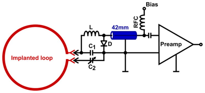
The implanted part is indicated in red. The coil element uses two capacitors: a matching capacitor C1 and a variable tuning capacitor C2 that fine-tunes the resonance frequency. A detuning trap is formed around C1 using a hand-wound inductor L and a Diode D. A small coaxial cable, indicated in blue, connects coil and preamp transforming the element impedance to ZNM, the noise matched impedance for the preamplifier input. The coaxial cable also transforms the input impedance of the preamplifier to a short across D.
All preamplifiers were orientated in z-direction to minimize Hall effect issues within the GaAs FET (Possanzini and Boutelje, In: Proceedings of the 16th Annual Meeting of ISMRM, Toronto, Canada, 2008). The preamplifier circuit boards also contain a bias-T for the PIN diode, which allows biasing the PIN diode via the 42-mm coaxial cable.
A local detunable single-loop coil (d = 15 cm, inner diameter; 1 cm thickness) was used as a transmit coil. This transmit coil was made from printed circuit board and slightly curved to increase the space for the placement of the exterior part (circuit boards and preamplifiers) of the implanted coil. To mimic an awake fMRI setup, the coil was placed horizontally and as low as possible over the top of the head of the monkey without covering his eyes. The primary B1-field of the transmit coil is in the y-direction. This setup with local transmit makes the constructed coil system feasible for MR scanners with no body coil (e.g. head-only scanners) or with strong gradient inserts (such as the AC88, Siemens, Erlangen) where the body coil is disabled.
2.3 Coil Surgery
Before the surgery the implanted part was sterilized using ethylene oxide gas. The headpost and coil were implanted during a single surgery and were fixed to the skull using dental acrylic (C&B Metabond) and 13 ceramic screws. The surgery was similar to a standard head post surgery (Vanduffel et al., 2001). The only difference was that besides the plastic headpost, the implanted coil was fully embedded in the dental acrylic. During surgery, gas anesthesia was maintained with isoflurane (1.5%) via an endotracheal tube.
Ultimately, this procedure created a three-layer electrical insulation that also increases the biocompatibility between the conductive part of the coil and the biological tissue (Fig. 1d). First the polyester coating of the wire, second the liquid Teflon layer, and third the embedding of the coated wires in dental acrylic. During the surgery and when the monkey was not being scanned, small caps protected the 8 implanted connectors. These protective caps were constructed from the male counterparts of the MCX connectors. These caps were made as small as possible and the backside was closed with solder. To make sure that the monkey could not remove these caps, small ridges of dental acrylic were implemented in the headpost around the caps.
Antibiotics (25 mg/kg Cephazoline, Noveplus LLC, Irving, TX, USA) and analgesics (0.01mg/kg Buprenex, Reckitt Benckiser Healthcare Ltd., Slough, UK) were given daily for, respectively 5 and 3 days following the surgery. The surgical procedures conformed to National Institutes of Health (NIH) guidelines for the care and use of laboratory animals. The total size of the constructed headpost acrylic was comparable to those of other macaques in our institution with multiple recording wells. More than six months after implantation, the monkey is currently being trained to perform behavioral tasks inside the scanner. The monkey does not show any signs of discomfort from the implanted array and the array is still working without any signs of deterioration.
2.4 External Coils
Three external monkey fMRI coils were used for comparing the performance of the implanted array: a horizontal receive-only coil (d = 10 cm) and a tight-fitting 4- (d = 6 cm), and 8-channel (4.5 cm) array coil.
The single loop coil was constructed out of printed circuit board and contains 12 equally spaced capacitors. The external phased array coils consist of two panels, each with two or four channels on both sides of the monkey’s head (Mareyam et al., In: Proceedings of the 19th Annual Meeting of ISMRM, Montreal, Canada, 2011). The array loops consisted of 16 AWG wire (Wiggins et al., 2006) that was positioned into a 3D-printed plastic holder. Each loop is broken up at one location, opposite to the driving point, at which a tunable capacitor was placed. The two panels of the arrays are positioned as close as possible to both sides of the monkey head while not obstructing the head post and eyes. The same local transmit coil as for the implant coil was also used for the external 4- and 8-channel coils. However, the standard body transmit coil was used during measurements with the single-channel receive coil.
2.5 Coil Bench Tests
The procedures for bench testing during construction were described previously (Keil et al., 2011). In short, bench measurements verified the element tuning, active detuning, nearest-neighbor coupling, and preamplifier decoupling for each coil element. In addition, the ratio of unloaded-to-loaded quality factor (QU/QL) was measured for each of the eight coil elements. QU/QL ratios were obtained with the element under test placed as an isolated resonant loop (no coaxial cable or preamplifier) within the populated but detuned array.
After populating all of the elements, the detuning trap circuits were adjusted so that elements not under test could be actively detuned using the coil-plug simulator. Active detuning was measured with a S21 measure between two decoupled (~80 dB) inductive probes slightly coupled to the array element under test. Nearest-neighbor coupling was measured using a direct S21 measurement between pairs of elements with coaxial cables directly connected to the preamplifier sockets of the two elements under test. The wires forming the loops were bent to empirically optimize the decoupling, while watching the S12 measure between the two loops under test to optimize the decoupling. When measuring the S21 between an adjacent coil pair, all other elements of the array were detuned.
We measured the preamplifier decoupling of a given loop with all other loops detuned. Preamplifier decoupling was measured as the change in the double-probe S21, when the coil drive coax was terminated in each of two different match conditions (Reykowski et al., 1995). In the first case, the coil is terminated with the powered low-impedance pre-amplifier. In the second case, the coil is terminated with a “power match” load by a dummy preamp consisting of a lumped element termination of impedance ZNM*.
2.6 MRI Data Acquisition and Reconstruction
Anesthetized monkey data were acquired on a 3 T clinical MRI Siemens scanner (MAGNETOM, Trio Tim system, Siemens Healthcare, Erlangen, Germany) with an insert head gradient (AC88, 80 mT/ m, slew rate = 400 T/ m/ s, Siemens Healthcare, Erlangen, Germany).
To measure SNR, proton density-weighted gradient echo images (TR/TE/α = 30 ms/6 ms/30°, slice = 1.5 mm, 40 slices, matrix: 128 × 128, FOV: 128 × 128 mm2, and BW = 200 Hz/pixel) were acquired. Coil array noise correlation information was acquired using the same pulse sequence but with no RF excitation. The SNR maps were calculated for images formed from noise covariance-weighted root sum-of-squares (cov-rSoS) combination of the individual channel images (Kellman and McVeigh, 2005; Roemer et al., 1990). The same gradient echo sequence was used for G-factor calculations. For the G-factor calculations the FOV and matrix size were cropped offline according the size of the monkey to achieve a tight FOV (96 mm × 96 mm). The G-factor maps were calculated to assess noise amplification in SENSE reconstructions caused by the numerically ill-conditioned unaliasing of the accelerated images and are estimated from the complex-valued coil sensitivity profiles and coil channel noise covariance matrix (Pruessmann et al., 1999). The maximum G-factor was determined after applying a 5×5 pixel mean filter to the G-factor maps to avoid biasing the maximum G-factor by outliers. In addition to the SNR data acquired with the implanted 8-channel array, data were compared with those obtained with the external single, 4-, and 8-channel coils in the same monkey.
High-resolution anatomical imaging with the implanted coil was demonstrated using a T1-weighted three-dimensional MPRAGE sequence, with TR/ inversion time (TI)/TE/α = 2.7 s/850 ms/3.74 ms/9°, matrix = 512 × 512 × 240, 200 μm isotropic voxel size, BW = 180 Hz/pixel, 4 averages, and an acquisition time per run of 23 min. In addition, high-resolution DTI images were acquired with the implanted array. 2D single-shot twice-refocused DW-SE-EPI were acquired at 0.7 mm isotropic using TR/TE = 6960/77 ms, matrix size = 148 × 148, R = 3, partial Fourier = 6/8, 61 slices, BW = 1408 Hz/pixel, 5 averages of 256 directions at b=1000 s/mm2, and 50 b = 0 images interspersed every 9 volumes. Total diffusion acquisition was 3 hrs. Slices were prescribed axially with the monkey in the sphinx position. Finally, to demonstrate the possible use of the implant coil for high-resolution fMRI, GRE-EPI images were acquired at 0.5 mm isotropic acceleration rates R = 1–4. Images were acquired using parameter values appropriate for functional imaging using BOLD contrast (axial slices, phase encoding direction = head-foot, TR/TE = 3000 ms/31 ms, matrix = 150 × 150, 0.5 mm isotropic voxel size, BW=1010 Hz/pixel, 100 time points). Due to hardware limitations in gradient strength, it was impossible to collect full-brain images using these parameters. To reach near full-brain coverage the number of slices (Nsl) was maximized for a fixed TR/TE, a distance factor of 20%, and partial Fourier acquisition (PF-factor) was used (R = 1: PF = 5/8, Nsl = 25; R = 2: PF = 6/8, Nsl = 38; R = 3: PF = 7/8, Nsl = 47; R = 4: PF = 8/8, Nsl = 53). To quantify the temporal stability of the GRE-EPI images, the time-course SNR (tSNR) was determined for each voxel as the mean value across the 100 time points divided by its temporal standard deviation.
3. Results
The QU/QL-ratios of the constructed implanted 8-channel coil ranged from 135/75 = 1.8 (for the smallest, frontal loop) to 155/35 = 4.4 (for the largest, central loop). Thus, the latter shows still sample-noise dominance, whereas, the smaller sized loops show equal distribution between coil noise and sample noise. The coupling between nearest neighbor elements as measured on the bench ranged from -13 dB to -27 dB with an average of -18 dB (Fig. 3a). The next-to-neighbor coupling ranges from -5 to -12 dB. Similar values were obtained for the external array coils. The elements received an average additional reduction of 22 dB from preamplifier decoupling (Fig. 3b). During the transmit state, the active detuning provided an isolation of the receive elements of on average -46 dB (Fig. 3c).
Figure 3. Typical s-parameter plots.

(a) Typical geometric decoupling of two adjacent loops of the coil. S11 (blue) and S22 (red) measures are shown on a Smith chart. The S21 measurement is depicted in a log-mag format. The S11 and S22 measurement shows that both elements are impedance matched to 50 Ω at 123.25 MHz. The S21 parameter shows a coupling between the channels of -18 dB. (b) Preamplifier decoupling of typical loop as measured with two decoupled inductive probes. For this element the difference in S21 at 123.25 MHz between the states with the preamplifier (red) and with a dummy load (black) at the preamplifier input is -19 dB. (c) Active detuning of a typical loop as measured with two decoupled inductive probes. For this loop the difference in S21 at 123.25MHz between the states with (red) and without (black) the 10V bias voltage is -52dB.
Figure 4 shows the representative noise correlation coefficient matrix for the external 4- and 8- channel and implanted 8-channel coils obtained from noise-only in vivo images. For the implanted array the noise correlation coefficients range from 0.16% to 27% with an average over all channels of 10% for the off-diagonal elements. These values are in between those of the external 4- and 8-channel coils, which range from 10% to 32% with an average of 19% and from 0.16% to 10% with an average of 5%, respectively.
Figure 4. Noise correlation matrices of the external 4- and 8-, and implanted 8-channel coil.

The mean noise correlation between two individual channels is 19%, 5%, and 10%, respectively; the minimum noise correlation is 10%, 0.2%, and 0.2%, respectively; the maximum noise correlation is 32%, 12%, and 27%, respectively. Noise covariance information was acquired using the same pulse sequence as for the SNR measurement but with no RF excitation.
Figure 5 shows an in vivo SNR comparison for images combined with the noise-covariance weighted root sum-of-squares (cov-rSoS) in 3 orthogonal planes. The same subject was used for all coils. In comparison with the external single-, 4-, and 8-channel coil, the implanted 8-channel coil showed an SNR increase in the periphery of the brain of 5.4-, 3.6-, and 3.4-fold respectively. In a region-of interest (ROI) covering the center of the brain, the SNR improvement with the implanted 8-channel coil was still 2.4-, 2.5, and 2.1-fold compared to the single-channel, 4-, and 8-channel coil, respectively. Both ROIs used for this measurement are shown in Fig. 5 as an overlay on the single-channel coil SNR map (center ROI in red; brain periphery ROI in white). For a ROI covering the entire brain, the relative SNR improvements obtained with the implanted array were 3.8, 3.0, and 2.8 compared to the external single-, 4-, and 8-channel coil respectively.
Figure 5. In vivo SNR comparisons in 3 orthogonal slices between the external 1-, 4-, and 8-and implanted 8-channel coil.

The SNR produced by the implanted coil is significantly higher than by the external coils. The SNR maps (log scale) were calculated for images formed from noise-covariance weighted root sum-of-squares (cov-rSoS) of the individual channel images. The central and peripherical ROI are indicated on the images obtained with the 1-channel coil.
Figure 6 shows the in vivo inverse G-factor maps in the transverse plane for one-dimensional and two-dimensional acceleration for all the multi-channel coils. Table 1 shows the average and peak G-factors, where the latter reflect the worst-case scenario regarding noise amplifications during parallel image reconstruction. Compared to the external 4-, and 8-channel coils, the constructed implant coil produce overall lower G-factors in all cases. To quantify the regional G-factor improvement compared to the external coils, Table 1 contains the average G-factor in a central ROI and peripheral ROI of the brain. The improvements (lower G-factors) for the implanted array compared to the external coils were comparable in the central and peripheral brain region.
Figure 6. In vivo transverse maps of 1/G- factor obtained from the external 4- and 8-channel coil and the 8-channel implant array coil.

The square FOV (96mm × 96mm) was chosen as tight as possible around the monkey head to avoid underestimation of G-factors. The implanted array shows over-all lower average and peak G-factor values compared to the external 4- and 8-channel coil. Only after the G-factor calculations, the results were masked with an ROI covering the brain. The central and peripheral ROI are indicated next to the images of the 4-channel coil. For the 4-channel the images for acceleration rates 2 × 3 and 3 × 2 are not shown because for those cases the acceleration rate is larger than the number of coils.
Table 1.
Measured average G-Factor values for the external 4- and 8- and implanted 8-channel coil for one and two-dimensional acceleration directions in the periphery and center ROI. For the 4-channel coil, the acceleration rates R = 2×3 and R = 3×2 are not determined because the acceleration rate would be larger than the number of channels
| R = 2×1 | R = 3×1 | R = 4×1 | R = 1×2 | R = 1×3 | R = 1×4 | R = 2×2 | R = 2×3 | R = 3×2 | ||
|---|---|---|---|---|---|---|---|---|---|---|
| ROI = periphery | External 4CH | 1.06 | 2.35 | 9.79 | 1.04 | 1.74 | 4.80 | 1.30 | - | - |
| External 8CH | 1.04 | 1.37 | 2.24 | 1.03 | 1.31 | 2.00 | 1.12 | 1.68 | 1.64 | |
| Implanted 8CH | 1.02 | 1.14 | 1.36 | 1.02 | 1.16 | 1.69 | 1.08 | 1.37 | 1.42 | |
|
| ||||||||||
| ROI = center | External 4CH | 1.09 | 2.69 | 11.55 | 1.05 | 2.53 | 6.78 | 1.55 | - | - |
| External 8CH | 1.11 | 1.70 | 3.28 | 1.07 | 1.86 | 3.56 | 1.26 | 2.47 | 2.19 | |
| Implanted 8CH | 1.04 | 1.17 | 1.55 | 1.01 | 1.31 | 2.43 | 1.14 | 1.67 | 1.44 | |
Figure 7 shows a full-brain unaccelerated MPRAGE image (average over 4 acquisitions, 200 μm isotropic resolution) acquired with the 8-channel implanted coil. The higher SNR translates to improved image quality in the MPRAGE for high-resolution spatial imaging of the entire cerebral cortex. In the dorsal and posterior regions the SNR and contrast are high enough to visualize detailed structures, such as the line of Gennari in area V1 in the occipital lobe. Only in the most ventral and anterior part of the brain the SNR becomes relatively low due to the physically restricted geometry of the coil.
Figure 7. High-resolution anatomical MPRAGE images acquired with the implanted coil.
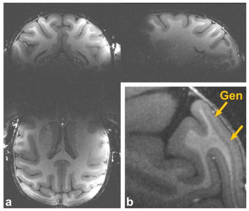
(a) 3 orthogonal views of an anatomical MPRAGE image acquired with the implanted coil at 200 μm isotropic spatial resolution, 4 averages, total scan time = 92 min. (b) A closeup of a sagittal slice showing a part of the area around V1. The line of Gennari in V1 is indicated with yellow arrows.
Figure 8 shows a high-resolution diffusion tensor image in the axial, sagittal, and coronal direction, including maps of directionally encoded color and fractional anisotropy. The images were acquired in a single session with 0.7 mm isotropic spatial resolution using the implanted 8-channel array. The higher SNR and temporal stability can be used to acquire high-resolution DTI with less image distortions in a shorter acquisition time.
Figure 8. High-resolution diffusion tensor images acquired with the implanted coil.

DTI including maps of (a) directionally encode color (red, green and blue representing L-R, A-P and S-I respectively) and (b) fractional anisotropy. Images were acquired at 3 T with a head-insert gradient (Gmax = 80 mT/m) and an 8-channel implant coil. Imaging parameters were R=3, b=1000 s/mm2, 256 directions and 5 averages. The total scan time was 3 hours.
Figure 9a shows a transversal slice for a near-full brain EPI volume acquired using parameter values chosen for BOLD imaging (TR/TE = 3 s/31 ms) using acceleration rates R = 1–4. In figure 9b the tSNR images of the same slice and acceleration rates is shown. For acceleration rates R=1–3 the majority of gray matter voxels have a tSNR level higher or equal to 20, which is sufficient for an fMRI analysis. Only in the most anterior areas the tSNR is rather low at this high resolution. The noise in the EPI volumes is consistent with the inverse G-factor maps. The noise level increases with the acceleration rate, yet only at 4-fold acceleration does the additional noise amplification begin to significantly degrade the image quality. Furthermore, the susceptibility and motion artifacts at the edges of the brain diminish as the acceleration rate is increased.
Figure 9. High-resolution GRE-EPI images acquired with the implanted coil.

(a) Horizontal slices from a near-full brain GRE-EPI volume acquired at acceleration rate 1–4 in 3s. (b) Time-course SNR maps of the same slices and acceleration rates. The applied partial Fourier encoding is indicated on the figure. Imaging parameters: TR/TE = 3000 ms/31 ms, single volumes, BW = 1010 Hz/Px, 100 time points.
4. Discussion
In this study, we present the design, construction, and characterization of an 8-channel receive-only array coil implanted onto the skull of a macaque monkey. The characterization of coil performance included the evaluation of noise correlation, SNR, G-factor maps, and high resolution in vivo imaging of a healthy adult male rhesus monkey.
The range between QU/QL-ratios shows non-uniform noise source contributions between the constructed array coil elements. While the larger loops show moderate sample-noise dominance (155/35 = 4.4), the smaller array loops show noise equally distributed between sample and coil components (135/75 = 1.8). The noise correlation coefficient between the coil elements of the implanted array revealed a mean coupling value of 10%—all correlation values were in the same range as those of the external 4- and 8-channel coil.
The SNR gain from the external 8-channel coil was only slightly higher than that of the external 4-channel coil. Due to the limited space around the head of a monkey, the placement of a coil with a large number of channels becomes difficult. This suggests that an even further increase in the number of channels for a monkey array coil would not translate into large gain factors. The use of the implanted 8-channel coil, however, resulted in an average SNR gain in the monkey brain of 3.8, 3.0, and 2.8 compared to an external single-, 4-, and 8-channel coil, respectively. This gain in SNR can be used to increase the spatial resolution of the MRI measurements. Because of the spatial SNR variation associated with array coils, the SNR gain of the constructed implanted array coil was higher at the periphery of the brain, but significant improvements at the center were also found. Higher SNR can also be obtained by acquiring multiple images and averaging, although this method is less efficient because the SNR only increases with the square root of the number of acquisitions. In addition, the implanted array provides improved temporal signal stability within and across scan sessions due to the fact that the array is always in the same position relative to the monkey’s brain.
G-factors for the implanted 8-channel coil show the highest noise amplification in the anterior and central brain regions. Comparisons between G-factor maps obtained with the external coils and the constructed implanted 8-channel array coil show overall significantly more favorable G-factors for the 8-channel implant array. The G-factor improvements compared to the 8-channel coil can be attributed to the closer fitting elements that offer a stronger spatial modulation of signal intensity and thus improved ability to unalias folded images (SENSE method) or synthesize spatial harmonics (SMASH or GRAPPA methods).
The improved SNR and acceleration capabilities obtained with the implanted coil allow us to increase spatial resolution for structural, diffusion tensor, and functional imaging. Here, we showed full-brain structural images that have enough contrast and SNR to reveal detailed structures at 200 μm isotropic after 4 acquisitions, obtained in only 92 min. Furthermore, detailed diffusion tensor-weighted images were acquired in a single session at 0.7 mm isotropic. This spatial resolution is almost 3 times higher as recently reported in vivo high-resolution DTI experiments on macaque at 3 T (Liu et al., 2010). The diffusion weighted data shown here have been used by McNab and colleagues in a comparative study with human data (McNab et al., In: Proceedings of the 20th Annual Meeting of ISMRM, Melbourne, Australia, 2012), indicating the quality of the data. Thirdly, the quality of the acquired GRE-EPI images suggest that, with an implanted phased array, functional imaging using BOLD contrast at 3 T with a spatial resolution of 0.5 mm isotropic and near full-brain coverage is within possibility. For such functional studies using this 8-channel implanted coil, the optimum acceleration rate would be 2- or 3-fold, making a compromise between minimizing the partial Fourier factor, maximizing the FOV, and limiting the decrease in SNR caused by the G-factor. The obtained tSNR maps can be tentatively compared to recently reported results by Goense and colleagues (Goense et al., 2010a) in which the use of a flexible, linear receive array for macaques was presented. In this study an image of the inverse of the coefficient of variation was presented, which corresponds to our definition of tSNR. Taking into account the 4 times smaller voxel size and the difference in flip angle used in the tSNR measurements, we approximately estimate the gain factor of the implanted coil to be around 1.5–2 in tSNR compared to the results reported by Goense and colleagues, even though the latter study was done at 7 T. In addition, the implanted array coil approach, as reported here, provides improved coverage of the brain.
5. Conclusions
An 8-channel array coil for macaque imaging was implanted in an adult macaque monkey and tested with in vivo MRI scans. We compared the capabilities of the implanted array to a conventional external single-, 4-, and 8-channel coil. The implanted coil provided significant SNR gain over both external coils. Significant improvements in parallel imaging performance were also obtained. The use of the implanted coil allowed us to acquire very high spatial resolution structural images (200 μm isotropic) and DTI volumes (0.7 mm isotropic) with full-brain coverage and GRE-EPI volumes that are suited for high-resolution fMRI (0.5 mm isotropic) with near full-brain coverage.
Acknowledgments
The authors thank H. Deng for the technical support during the scans. This work received support from Inter University Attraction Pole 6/29, Program Financing PFV/10/008, Geconcerteerde Onderzoeks Actie 10/19, Hercules funding, Fonds Wetenschappelijk Onderzoek (FWO)–Vlaanderen, G062208N10, G083111N10, and G043912N, and NSF grant BCS-0745436. TJ is an aspirant of the FWO-Vlaanderen. The Martinos Center is supported by National Center for Research Resources grant P41RR14075.
Footnotes
Publisher's Disclaimer: This is a PDF file of an unedited manuscript that has been accepted for publication. As a service to our customers we are providing this early version of the manuscript. The manuscript will undergo copyediting, typesetting, and review of the resulting proof before it is published in its final citable form. Please note that during the production process errors may be discovered which could affect the content, and all legal disclaimers that apply to the journal pertain.
References
- Adluru N, Zhang H, Fox AS, Shelton SE, Ennis CM, Bartosic AM, Oler JA, Tromp do PM, Zakszewski E, Gee JC, Kalin NH, Alexander AL. A diffusion tensor brain template for rhesus macaques. Neuroimage. 2012;59:306–318. doi: 10.1016/j.neuroimage.2011.07.029. [DOI] [PMC free article] [PubMed] [Google Scholar]
- Arcaro MJ, Pinsk MA, Li X, Kastner S. Visuotopic organization of macaque posterior parietal cortex: a functional magnetic resonance imaging study. J Neurosci. 2011;31:2064–2078. doi: 10.1523/JNEUROSCI.3334-10.2011. [DOI] [PMC free article] [PubMed] [Google Scholar]
- Bell AH, Hadj-Bouziane F, Frihauf JB, Tootell RB, Ungerleider LG. Object representations in the temporal cortex of monkeys and humans as revealed by functional magnetic resonance imaging. J Neurophysiol. 2009;101:688–700. doi: 10.1152/jn.90657.2008. [DOI] [PMC free article] [PubMed] [Google Scholar]
- Disbrow EA, Slutsky DA, Roberts TP, Krubitzer LA. Functional MRI at 1.5 tesla: a comparison of the blood oxygenation level-dependent signal and electrophysiology. Proc Natl Acad Sci U S A. 2000;97:9718–9723. doi: 10.1073/pnas.170205497. [DOI] [PMC free article] [PubMed] [Google Scholar]
- Ekstrom LB, Roelfsema PR, Arsenault JT, Bonmassar G, Vanduffel W. Bottom-up dependent gating of frontal signals in early visual cortex. Science. 2008;321:414–417. doi: 10.1126/science.1153276. [DOI] [PMC free article] [PubMed] [Google Scholar]
- Ekstrom LB, Roelfsema PR, Arsenault JT, Kolster H, Vanduffel W. Modulation of the contrast response function by electrical microstimulation of the macaque frontal eye field. J Neurosci. 2009;29:10683–10694. doi: 10.1523/JNEUROSCI.0673-09.2009. [DOI] [PMC free article] [PubMed] [Google Scholar]
- Goense J, Logothetis NK, Merkle H. Flexible, phase-matched, linear receive arrays for high-field MRI in monkeys. Magn Reson Imaging. 2010a;28:1183–1191. doi: 10.1016/j.mri.2010.03.026. [DOI] [PubMed] [Google Scholar]
- Goense JB, Whittingstall K, Logothetis NK. Functional magnetic resonance imaging of awake behaving macaques. Methods. 2010b;50:178–188. doi: 10.1016/j.ymeth.2009.08.003. [DOI] [PubMed] [Google Scholar]
- Hadj-Bouziane F, Bell AH, Knusten TA, Ungerleider LG, Tootell RB. Perception of emotional expressions is independent of face selectivity in monkey inferior temporal cortex. Proc Natl Acad Sci U S A. 2008;105:5591–5596. doi: 10.1073/pnas.0800489105. [DOI] [PMC free article] [PubMed] [Google Scholar]
- Hergt M, Oppelt R, Vester M, Reykowski A, Huber K, Jahns K, Fischer H. Proceedings of the 15th Annual Meeting of ISMRM 2007. Low noise preamplifier with integrated cable trap; Berlin, Germany. p. 1037. [Google Scholar]
- Keil B, Alagappan V, Mareyam A, McNab JA, Fujimoto K, Tountcheva V, Triantafyllou C, Dilks DD, Kanwisher N, Lin W, Grant PE, Wald LL. Size-optimized 32-channel brain arrays for 3 T pediatric imaging. Magn Reson Med. 2011;66:1777–1787. doi: 10.1002/mrm.22961. [DOI] [PMC free article] [PubMed] [Google Scholar]
- Kellman P, McVeigh ER. Image reconstruction in SNR units: a general method for SNR measurement. Magn Reson Med. 2005;54:1439–1447. doi: 10.1002/mrm.20713. [DOI] [PMC free article] [PubMed] [Google Scholar]
- Khachaturian MH. A 4-channel 3 Tesla phased array receive coil for awake rhesus monkey fMRI and diffusion MRI experiments. J Biomed Sci Eng. 2010;3:1085–1092. doi: 10.4236/jbise.2010.311141. [DOI] [PMC free article] [PubMed] [Google Scholar]
- Khachaturian MH, Arsenault J, Ekstrom LB, Tuch DS, Vanduffel W. Focal reversible deactivation of cerebral metabolism affects water diffusion. Magn Reson Med. 2008;60:1178–1189. doi: 10.1002/mrm.21810. [DOI] [PMC free article] [PubMed] [Google Scholar]
- Kim SG, Ugurbil K. High-resolution functional magnetic resonance imaging of the animal brain. Methods. 2003;30:28–41. doi: 10.1016/s1046-2023(03)00005-7. [DOI] [PubMed] [Google Scholar]
- Kolster H, Mandeville JB, Arsenault JT, Ekstrom LB, Wald LL, Vanduffel W. Visual field map clusters in macaque extrastriate visual cortex. J Neurosci. 2009;29:7031–7039. doi: 10.1523/JNEUROSCI.0518-09.2009. [DOI] [PMC free article] [PubMed] [Google Scholar]
- Leite FP, Tsao D, Vanduffel W, Fize D, Sasaki Y, Wald LL, Dale AM, Kwong KK, Orban GA, Rosen BR, Tootell RB, Mandeville JB. Repeated fMRI using iron oxide contrast agent in awake, behaving macaques at 3 Tesla. Neuroimage. 2002;16:283–294. doi: 10.1006/nimg.2002.1110. [DOI] [PubMed] [Google Scholar]
- Liu X, Zhu T, Gu T, Zhong J. Optimization of in vivo high-resolution DTI of non-human primates on a 3T human scanner. Methods. 2010;50:205–213. doi: 10.1016/j.ymeth.2009.06.008. [DOI] [PubMed] [Google Scholar]
- Logothetis N, Merkle H, Augath M, Trinath T, Ugurbil K. Ultra high-resolution fMRI in monkeys with implanted RF coils. Neuron. 2002;35:227–242. doi: 10.1016/s0896-6273(02)00775-4. [DOI] [PubMed] [Google Scholar]
- Logothetis NK, Guggenberger H, Peled S, Pauls J. Functional imaging of the monkey brain. Nat Neurosci. 1999;2:555–562. doi: 10.1038/9210. [DOI] [PubMed] [Google Scholar]
- Logothetis NK, Pauls J, Augath M, Trinath T, Oeltermann A. Neurophysiological investigation of the basis of the fMRI signal. Nature. 2001;412:150–157. doi: 10.1038/35084005. [DOI] [PubMed] [Google Scholar]
- Makris N, Papadimitriou GM, van der Kouwe A, Kennedy DN, Hodge SM, Dale AM, Benner T, Wald LL, Wu O, Tuch DS, Caviness VS, Moore TL, Killiany RJ, Moss MB, Rosene DL. Frontal connections and cognitive changes in normal aging rhesus monkeys: a DTI study. Neurobiol Aging. 2007;28:1556–1567. doi: 10.1016/j.neurobiolaging.2006.07.005. [DOI] [PubMed] [Google Scholar]
- Mandeville JB, Marota JJ, Ayata C, Moskowitz MA, Weisskoff RM, Rosen BR. MRI measurement of the temporal evolution of relative CMRO(2) during rat forepaw stimulation. Magn Reson Med. 1999;42:944–951. doi: 10.1002/(sici)1522-2594(199911)42:5<944::aid-mrm15>3.0.co;2-w. [DOI] [PubMed] [Google Scholar]
- Mantini D, Gerits A, Nelissen K, Durand JB, Joly O, Simone L, Sawamura H, Wardak C, Orban GA, Buckner RL, Vanduffel W. Default mode of brain function in monkeys. J Neurosci. 2011;31:12954–12962. doi: 10.1523/JNEUROSCI.2318-11.2011. [DOI] [PMC free article] [PubMed] [Google Scholar]
- Mareyam A, Blau J, Polimeni J, Keil B, Farivar R, Benner T, Vanduffel W, Wald LL. Proceedings of the 19th Annual Meeting of ISMRM, Montreal, Canada. 2011; Eight-channel array coil optimized for functional imaging of awake monkeys at 7T; Montreal, Canada. p. 1823. [Google Scholar]
- Matsui T, Tamura K, Koyano KW, Takeuchi D, Adachi Y, Osada T, Miyashita Y. Direct comparison of spontaneous functional connectivity and effective connectivity measured by intracortical microstimulation: an FMRI study in macaque monkeys. Cereb Cortex. 2011;21:2348–2356. doi: 10.1093/cercor/bhr019. [DOI] [PubMed] [Google Scholar]
- McNab JA, Polimeni JR, Wang R, Augustinack JC, Fujimoto K, Player A, Triantafyllou C, Janssens T, Farivar R, Vanduffel W, Wald LL. Proceedings of the 20th Annual Meeting of ISMRM, Melbourne, Australia. 2012; Comparison of In Vivo Human, In Vivo Macaque and Ex Vivo Human Measurements of Diffusion Orientation in the Cerebral Cortex; Melbourne, Australia. p. 3756. [Google Scholar]
- Moeller S, Freiwald WA, Tsao DY. Patches with links: a unified system for processing faces in the macaque temporal lobe. Science. 2008;320:1355–1359. doi: 10.1126/science.1157436. [DOI] [PMC free article] [PubMed] [Google Scholar]
- Nelissen K, Borra E, Gerbella M, Rozzi S, Luppino G, Vanduffel W, Rizzolatti G, Orban GA. Action observation circuits in the macaque monkey cortex. J Neurosci. 2011;31:3743–3756. doi: 10.1523/JNEUROSCI.4803-10.2011. [DOI] [PMC free article] [PubMed] [Google Scholar]
- Nelissen K, Vanduffel W. Grasping-related functional magnetic resonance imaging brain responses in the macaque monkey. J Neurosci. 2011;31:8220–8229. doi: 10.1523/JNEUROSCI.0623-11.2011. [DOI] [PMC free article] [PubMed] [Google Scholar]
- Nelissen K, Vanduffel W, Orban GA. Charting the lower superior temporal region, a new motion-sensitive region in monkey superior temporal sulcus. J Neurosci. 2006;26:5929–5947. doi: 10.1523/JNEUROSCI.0824-06.2006. [DOI] [PMC free article] [PubMed] [Google Scholar]
- Pfeuffer J, Shmuel A, Keliris GA, Steudel T, Merkle H, Logothetis NK. Functional MR imaging in the awake monkey: effects of motion on dynamic off-resonance and processing strategies. Magn Reson Imaging. 2007;25:869–882. doi: 10.1016/j.mri.2007.03.002. [DOI] [PubMed] [Google Scholar]
- Possanzini C, Boutelje M. Proceedings of the 16th Annual Meeting of ISMRM, Toronto, Canada. 2008; Influence of magnetic field on preampli- fiers using GaAs FET technology; Toronto, Canada. p. 1123. [Google Scholar]
- Pruessmann KP, Weiger M, Scheidegger MB, Boesiger P. SENSE: sensitivity encoding for fast MRI. Magn Reson Med. 1999;42:952–962. [PubMed] [Google Scholar]
- Reykowski A, Wright SM, Porter JR. Design of matching networks for low noise preamplifiers. Magn Reson Med. 1995;33:848–852. doi: 10.1002/mrm.1910330617. [DOI] [PubMed] [Google Scholar]
- Roemer PB, Edelstein WA, Hayes CE, Souza SP, Mueller OM. The NMR phased array. Magn Reson Med. 1990;16:192–225. doi: 10.1002/mrm.1910160203. [DOI] [PubMed] [Google Scholar]
- Stefanacci L, Reber P, Costanza J, Wong E, Buxton R, Zola S, Squire L, Albright T. fMRI of monkey visual cortex. Neuron. 1998;20:1051–1057. doi: 10.1016/s0896-6273(00)80485-7. [DOI] [PubMed] [Google Scholar]
- Tsao DY, Freiwald WA, Knutsen TA, Mandeville JB, Tootell RB. Faces and objects in macaque cerebral cortex. Nat Neurosci. 2003a;6:989–995. doi: 10.1038/nn1111. [DOI] [PMC free article] [PubMed] [Google Scholar]
- Tsao DY, Vanduffel W, Sasaki Y, Fize D, Knutsen TA, Mandeville JB, Wald LL, Dale AM, Rosen BR, Van Essen DC, Livingstone MS, Orban GA, Tootell RB. Stereopsis activates V3A and caudal intraparietal areas in macaques and humans. Neuron. 2003b;39:555–568. doi: 10.1016/s0896-6273(03)00459-8. [DOI] [PubMed] [Google Scholar]
- Vanduffel W, Fize D, Mandeville JB, Nelissen K, Van Hecke P, Rosen BR, Tootell RB, Orban GA. Visual motion processing investigated using contrast agent-enhanced fMRI in awake behaving monkeys. Neuron. 2001;32:565–577. doi: 10.1016/s0896-6273(01)00502-5. [DOI] [PubMed] [Google Scholar]
- Wiggins GC, Polimeni JR, Potthast A, Schmitt M, Alagappan V, Wald LL. 96-Channel receive-only head coil for 3 Tesla: design optimization and evaluation. Magn Reson Med. 2009;62:754–762. doi: 10.1002/mrm.22028. [DOI] [PMC free article] [PubMed] [Google Scholar]
- Wiggins GC, Triantafyllou C, Potthast A, Reykowski A, Nittka M, Wald LL. 32-channel 3 Tesla receive-only phased-array head coil with soccer-ball element geometry. Magn Reson Med. 2006;56:216–223. doi: 10.1002/mrm.20925. [DOI] [PubMed] [Google Scholar]
- Wright SM, Wald LL. Theory and application of array coils in MR spectroscopy. NMR Biomed. 1997;10:394–410. doi: 10.1002/(sici)1099-1492(199712)10:8<394::aid-nbm494>3.0.co;2-0. [DOI] [PubMed] [Google Scholar]