Abstract
The in vitro investigation of many optically opaque biological microstructures requires 3D analysis at high resolution over a large field of view. We demonstrate a new nondestructive volumetric imaging technique that eliminates the structural and computational limitations of conventional 2D optical microscopy by combining x-ray phase-contrast tomography with critical point drying sample preparation. We experimentally demonstrate the enhancement of small features afforded by phase-contrast imaging and show the contrast improvement afforded by the drying of a hydrated specimen. We further demonstrate the biological application of this technique by imaging the microstructure of the accommodative apparatus in a primate eye using a benchtop phase-contrast tomography system.
OCIS codes: (110.7440) X-ray imaging; (170.3880) Medical and biological imaging; (170.4470) Ophthalmology; (170.6935) Tissue characterization; (170.6960) Tomography; (330.7322) Visual optics, accommodation; (350.5030) Phase
1. Introduction
Although biological cells, tissues, and organs are three-dimensional (3D) structures, their in vitro physiology and pathophysiology are to this day primarily studied with two-dimensional (2D) imaging techniques (see, e.g., [1-3]). If the 3D nature of biological structures is not accounted for, key phenotypic and functional characteristics are often not recognized resulting in misinterpretations of the mechanisms responsible for both normal and disease processes.
Analysis of microscopic 3D biological structures is not a simple task. In fact, the microscopic analysis of biological structures generally requires destructive manipulation of the 3D tissue structures that are to be studied. In order to examine tissue under a light or transmission electron microscope, for example, the tissue is generally embedded in wax or plastic and then sliced into sections. Although the sectioning process is well known to introduce structural artifacts [4,5], the process allows light or electron beams to pass through the tissue and thereby enables a 2D image of the sliced material to be captured. Only as the 2D images of successive slices are layered together is the 3D nature of the tissue restored (see, e.g., [6]). Although computational techniques have facilitated and improved the accuracy of this process, a full accounting of 3D structures in intricate biological tissues remains a difficult, destructive, and time-consuming proposition.
Overcoming these limitations is key to advancing our understanding of how biological form follows function and how malformation leads to malfunction. In this work, we describe a new nondestructive method that combines benchtop high-resolution phase-contrast x-ray tomography with critical point drying to more fully account for microscopic 3D structures in opaque specimens.
In x-ray phase-contrast tomography, variations in the spatial distribution of a sample’s x-ray refractive index are employed to produce image contrast that augments or replaces conventional x-ray absorption contrast. Planar in-line phase-contrast imaging is a Gabor holography technique [7] that uses a highly-coherent input x-ray beam and a significant post-sample propagation distance to generate interference effects at tissue discontinuities. The resulting images contain a characteristic enhancement along sample edges and include intensity responses from small objects that can be practically invisible in traditional radiographic imaging. Gabor holography has been widely implemented with visible light sources [8,9]. In the x-ray regime, this technique was originally employed at synchrotron facilities [10-12] due to the brightness and high coherence of synchrotron x-ray sources, but the more recent use of microfocus x-ray tube sources, which produce fields with a high degree of spatial coherence, has enabled the creation of laboratory and clinical systems [13-15].
As in-line phase-contrast imaging derives contrast from refractive index variations, it is ideally suited for using air as a contrast agent. For example, studies have shown that the air-filled vasculature in liver specimens generates significant contrast by creating air-tissue refractive index discontinuities [16]. In an effort to study fine structures, such as the ciliary structures and zonules in the primate eye, we seek to exploit the contrast from air interfaces that may be introduced into these delicate microscopic structures. By marrying the critical point drying sample preparation technique, which is commonly used for electron microscopy, with x-ray phase-contrast tomography, the delicate structures of interest may be preserved while introducing contrast-rich air boundaries. The technique presented in this work allows for simultaneous large-scale and microscopic analysis without the destructive sectioning process that is required for microscopic evaluation.
2. Materials and methods
The benchtop in-line phase-contrast tomography system used in this work included a microfocus x-ray tube source (Thermo Kevex PXS10-65W; W anode, 7-100 μm spot size, 65 W maximum tube power, 45-130 kV peak voltage), a cooled high-resolution digital x-ray camera (Princeton Instruments Quad RO 4096; 16 μm pitch, 14-bit quantization), a three-axis sample positioning system (Thorlabs LTS150, XT95SP-1000), and a rotation stage for tomographic imaging (Thorlabs NR360S). The detector and sample positions were varied over the length of the table (2.4 m) to accommodate various specimen magnifications, system resolution requirements, and fields of view. In this study, the source-to-object distance varied from 14.3 cm to 68.4 cm and the object-to-detector distance varied from 25.2 cm to 120.3 cm. The system spatial resolution was calculated as
| (1) |
where s is the manufacturer-characterized spot size measured per the British Standard Method [17] and μm is the spatial detector blur estimated from a measured edge-spread function. Note that the tube current, which is directly related to the spot size and output flux from the microfocus tube source, was chosen to achieve the appropriate spot size and exposure time for a given experimental system geometry. The x-ray spectrum from the microfocus tube, when operated at 55 kV peak voltage, had an approximate minimum energy of 4 keV, a maximum energy of 55 keV, and an approximate mean energy of 16 keV.
The imaging model for boundary-enhanced phase-contrast tomography is described in detail elsewhere [18]. Briefly, under a thin-object approximation, which is valid for tissue due to the high x-ray energy employed here, the measured intensity can be expressed in terms of the complex sample refractive index , the system magnification , and as
| (2) |
where is the unperturbed intensity with the object absent, k is the wave number, is the position vector, z is the direction of propagation, and is the 2D Laplacian operator acting on the detector-plane coordinates x and y. Note that the Laplacian operator acting on the right-hand term brings about edge-enhancement by acting on the real part of the projected complex refractive index, while conventional absorption contrast is brought about by the Beer-Lambert Law as described by the first term on the right-hand side of the equation.
The function is the projection data used for tomographic reconstruction of the 3D volume data via the Feldkamp-Davis-Kress (FDK) algorithm for circular cone-beam imaging [19]. The FDK algorithm is a direct reconstruction weighted convolution-backprojection formula that attempts to compensate for the finite cone-angle in contrast to slice-by-slice reconstruction techniques using parallel- or fan-beam data. The algorithm has been shown to be highly accurate for use in microfocus x-ray CT experiments.
In this work, two specimens were selected for analysis. First, a formalin-fixed cranial defect [20] was used to demonstrate the phase-contrast enhancement brought about by the introduction of air into the sample via drying. This study was performed by removing the specimen from storage in a phosphate-buffered saline solution and drying via exposure to the room-temperature laboratory environment during imaging. Second, the anterior hemisphere of a previously-prepared critical point dried eye from an 11-year-old baboon was used for tomographic analysis and to demonstrate the enhancement of fine structures.
Critical point drying is commonly used to preserve small structures when preparing biological samples for scanning electron microscopy [21]. It avoids the creation of damaging surface tension forces associated with drying by bringing liquid in the sample to the gas phase without crossing the liquid-gas phase boundary. Briefly, the sample is generally prepared by flushing away water with acetone and then infusing it with high-pressure liquid carbon dioxide. The sample is subsequently heated until the pressure exceeds the critical point and the gaseous carbon dioxide is allowed to escape, leaving a dried sample. Great care must be taken when handling the dried specimen as fine structures are fragile. Detailed descriptions of critical point drying protocols are available elsewhere [22].
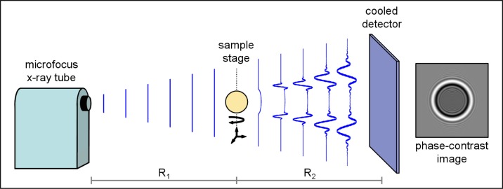
The critical point dried eye specimen was imaged using the benchtop in-line phase-contrast tomography system (Fig. 1 ). Tomographic data were acquired at 501 view angles (0.4-degree step) and reconstruction was performed using the FDK algorithm. Cornea and conjunctiva structures were removed from the reconstructed data by manual segmentation. Rendered 3D data were displayed using the Drishti volumetric visualization tool [23], which applies a two-dimensional transfer function to weight the opacity and color of each voxel.
Fig. 1.
In-line phase-contrast tomography system. The planar x-ray intensity is shown as it propagates from the microfocus source to the sample (distance R1) and from the sample to the detector (distance R2). Intensity fringes develop with propagation and are measured by a digital detector. An example simulated phase-contrast image of a sphere is shown on the right.
Changes in image appearance were quantitatively characterized by analysis of the image texture data. These data yield statistical information on the coarseness and smoothness of image content. Improved appearance of small structures, as is expected from phase-contrast imaging, results in increased coarseness of the image content, manifesting in increased sample variance and decreased uniformity. Image texture properties were quantified by analyzing the statistics of the image intensity histogram , where the overbar denotes a random variable and Ī is the intensity normalized to values of 0 to 255. The quantities of interest in this work are the sample variance
| (3) |
where E is the sample mean, and the uniformity
| (4) |
[24]. Low contrast, or smooth, regions are characterized by low sample variance and high uniformity.
3. Results and discussion
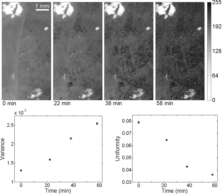
The introduction of air into the cranial defect sample is shown in Fig. 2 . The specimen images were acquired with system parameters of source-to-object distance 32.1 cm, object-to-detector distance 65.8 cm, magnification 3.05, approximate spot size 13 μm, tube voltage 55 kV, and tube current 200 μA, yielding an effective pixel size of 4.9 μm, and an estimated system resolution of 14 μm. As the specimen dried, the visibility of the of the fibrous poly-L-lactide scaffold microstructure (~40 μm fiber size) was improved dramatically. The change in contrast is due to the introduction of air interfaces into the specimen. As the refractive index difference between the specimen and surrounding air is much larger than the difference between the specimen and surrounding saline, the resulting refraction is much stronger and, thus, the phase contrast is improved. These results are qualitatively similar to those obtained in a previous study of air-contrast enhancement [14].
Fig. 2.
The contrast improvement induced by drying is shown here in projection images and plots of image histogram statistics. The cranial defect specimen, which was dried over a period of 58 minutes, shows fibrous polymer layer structures when dried (far right) that are relatively difficult to discern in the un-dried specimen (far left). Quantitative improvements in contrast are shown in the graphs of the time-dependent behavior of intensity histogram variance and uniformity. Note that the specimen occupies the entire frame in these images. The grayscale window is the same for all images.
Changes to the histogram statistics are shown in Fig. 2, where each image was sub-divided into 25 regions for analysis and the calculated mean and variance (error bars) over the regions are shown. The increased sample variance (63% difference, from 1.3 × 10⁻³ to 2.5 × 10⁻³) and decreased uniformity (74% difference, from 7.9 × 10⁻² to 3.6 × 10⁻²) with time indicates improved small feature contrast with drying. For comparison, an adjacent sample-absent image region containing only noise (not displayed) showed much smaller percentage differences in variance (18% difference, from 8.7 × 10⁻³ to 1.0 × 10⁻²) and uniformity (1% difference, from 0.121 to 0.122). The percentage differences are calculated as and . Finally, note that neither the phase-contrast technique nor the drying process limits the appearance of highly-absorbing calcified regions in these images.
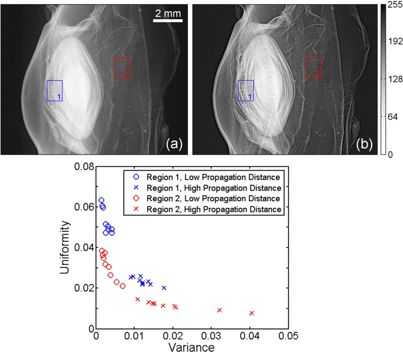
The enhancement of fine features due to phase-contrast imaging is shown in Fig. 3 . The dried eye specimen was imaged (55 kV, 7 μA, 5 μm) in two geometries, a low-propagation distance configuration (14.3 cm, 25.2 cm) and a high-propagation distance configuration (68.4 cm, 120.3 cm). Note that the magnification is held constant (2.76) in both cases so that the effective resolution of the detector is unchanged. It is clear from these data that the phase-contrast enhancement afforded by increased propagation distance improves the visualization of fine structures such as the layered structure of the crystalline lens. This result is expected, as increased propagation distance yields amplified edge-enhancement effects at discontinuities within the specimen. The resulting increased intensity variations in the high-propagation images were also expected to yield increased intensity variance and decreased intensity uniformity.
Fig. 3.
The effect of propagation distance on phase contrast in projection images of a critical point dried baboon eye. In the low-propagation case (left), the fine structure of the crystalline lens and focusing structures are relatively indistinct. In the high-propagation case (right), in which phase-contrast is enhanced, these features are more easily visualized. Quantitative assessment of image statistics in two regions (boxes in the images) shows the effect of phase-enhancement on intensity histogram variance and uniformity. The grayscale window is the same for both images.
Again, an analysis of image texture was performed to demonstrate the enhancement. The graph in Fig. 3 is a scatter plot showing the sample variance and uniformity over two regions in the low- and high-propagation images (indicated by boxes in Fig. 3(a) and Fig. 3(b)). Each region is divided into nine sub-regions, each denoted by a marker. For corresponding regions, the region-averaged variance is higher in the high-propagation distance image (1.7 × 10⁻²) than in the low-propagation distance image (2.9 × 10⁻³, 141% difference) and the region-averaged uniformity is lower in the high-propagation distance image (1.7 × 10⁻²) than in the low-propagation distance image (4.2 × 10⁻², 85% difference). This indicates that increased propagation distance increases the appearance of small features in the image data. For comparison, an adjacent sample-absent image region containing only noise showed much smaller percentage differences in variance (28% difference, from 7.2 × 10⁻³ to 9.5 × 10⁻³) and uniformity (13% difference, from 0.119 to 0.104).
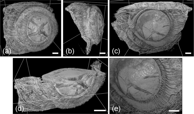
In the computed tomography study (55 kV, 400 μA, 30 μm, 45.2 cm, 107.3 cm, 3.37), an estimated system resolution of 23 μm was achieved with effective pixel size 4.5 μm. The 3D tomographic data shown in Figs. 4 and 5 demonstrate the large field of view and high resolution of this technique. The 3D volume-rendered data (Fig. 5), which are shown in anterior, posterior, and lateral views, capture the entire accommodative apparatus of the eye, including the lens and ciliary structures. The fine focusing apparatus is best visualized in the zoomed 3D volume-rendered image shown in Fig. 5(e), where the ciliary body, which appears as a set of fibrous structures surrounding the crystalline lens, is shown radiating outward from the lens body toward the posterior choroidal region. Also visible are the stratified lens structure and star-shaped surface sutures, which are well preserved during sample preparation and image reconstruction [25]. Transverse planar slices (Fig. 4) show detailed images of the ciliary region including the stratified layers of the lens and the morphologic configuration of the lens, iris, and ciliary structures [26]. For reference, the iris thickness in adult humans has been measured to be approximately 0.5 mm and from high-magnification histology data, the thickness of the ciliary body is approximately 0.2 mm [27,28].
Fig. 4.
Transverse slices of the reconstructed tomography data of a critical point dried baboon eye. The proximal plane slice in (a) clearly shows the iris (i), ciliary structures (ci), and choroid (ch). The distal plane slice in (b) additionally shows the crystalline lens (cl). Note that although there is little absorption contrast visible in the interior of many structures, boundaries display significant edge contrast (e.g., the iris). A threshold was applied to the data for display purposes. The grayscale window is the same for both images.
Fig. 5.
A 3D volumetric rendering of the focusing apparatus of a critical point dried baboon eye. Anterior (a), lateral (b), and posterior (c) images show the large field of view that can be captured relative to microscopy. The transverse slice data exposed in the anterior view (d) demonstrate the simultaneous visualization of interior and exterior sample structures. Finally, the zoomed-in posterior view (e) shows the highly detailed visualization of ciliary structures emanating from the crystalline lens. A threshold was applied to the volumetric data for display purposes. Scale bars are 1 mm in length.
4. Conclusion
X-ray phase-contrast tomography fills a significant void in the existing methods used for 3D analysis. Coupled with critical point drying, this imaging method holds great promise for a wide range of biological researches where improved methods for analysis of microstructure in optically opaque biological specimens are needed. Furthermore, the in-line phase-contrast tomography technique demonstrated here is widely applicable, as the laboratory system is contained on a benchtop, uses off-the-shelf components, and does not require access to an x-ray synchrotron source.
In the eye research field, especially in the study of focusing structures, the methods presented here have a high potential impact. While electron microscopy techniques offer higher resolution, 3D imaging of an intact specimen is an untapped capability in the eye research community, which typically employs destructive 2D light or electron microscopy techniques to study morphology [1-3]. The method presented here is expected to augment these existing techniques to facilitate improved study of the 3D lens structure and accommodation. The latter topic is of particular interest as morphological changes in the fine structures making up the accommodative apparatus are being studied to gain an understanding of their effect on the focusing actions of the eye. These studies stand to be significantly improved by the simultaneous large-scale and microscopic specimen analysis described here. Moreover, by avoiding the specimen sectioning process required for light and electron microscopy, a significant source of structural defects has been eliminated.
In this work, we have shown that the combination of critical point drying and benchtop x-ray phase-contrast tomography yields highly detailed volumetric images of small delicate structures. This method holds significant promise as an analytic technique to augment microscopy and enable nondestructive evaluation of optically opaque specimens.
Acknowledgments
This work was supported by the US National Institutes of Health under grants CA136102 (AMZ), CA111976 (MNW), and EB009715 (MAA) and the US National Science Foundation under grants CBET-0546113 (MAA) and CBET-0854430 (MAA). The authors gratefully acknowledge Antonios G. Mikos, F. Kurtis Kasper, and Patrick Spicer of Rice University for providing the cranial defect sample.
References and links
- 1.Lütjen-Drecoll E., Tamm E., Kaufman P. L., “Age changes in rhesus monkey ciliary muscle: light and electron microscopy,” Exp. Eye Res. 47(6), 885–899 (1988). 10.1016/0014-4835(88)90070-X [DOI] [PubMed] [Google Scholar]
- 2.Kuszak J. R., Peterson K. L., Brown H. G., “Electron microscopic observations of the crystalline lens,” Microsc. Res. Tech. 33(6), 441–479 (1996). [DOI] [PubMed] [Google Scholar]
- 3.Lütjen-Drecoll E., Kaufman P. L., Wasielewski R., Ting-Li L., Croft M. A., “Morphology and accommodative function of the vitreous zonule in human and monkey eyes,” Invest. Ophthalmol. Vis. Sci. 51(3), 1554–1564 (2010). 10.1167/iovs.09-4008 [DOI] [PMC free article] [PubMed] [Google Scholar]
- 4.Gardella D., Hatton W. J., Rind H. B., Rosen G. D., von Bartheld C. S., “Differential tissue shrinkage and compression in the z-axis: implications for optical disector counting in vibratome-, plastic- and cryosections,” J. Neurosci. Methods 124(1), 45–59 (2003). 10.1016/S0165-0270(02)00363-1 [DOI] [PubMed] [Google Scholar]
- 5.Jones A. S., Milthorpe B. K., Howlett C. R., “Measurement of microtomy-induced section distortion and its correction for 3-dimensional histological reconstructions,” Cytometry 15(2), 95–105 (1994). 10.1002/cyto.990150203 [DOI] [PubMed] [Google Scholar]
- 6.Dauguet J., Delzescaux T., Condé F., Mangin J.-F., Ayache N., Hantraye P., Frouin V., “Three-dimensional reconstruction of stained histological slices and 3D non-linear registration with in-vivo MRI for whole baboon brain,” J. Neurosci. Methods 164(1), 191–204 (2007). 10.1016/j.jneumeth.2007.04.017 [DOI] [PubMed] [Google Scholar]
- 7.Gabor D., “A new microscopic principle,” Nature 161(4098), 777–778 (1948). 10.1038/161777a0 [DOI] [PubMed] [Google Scholar]
- 8.Xu W., Jericho M. H., Meinertzhagen I. A., Kreuzer H. J., “Digital in-line holography for biological applications,” Proc. Natl. Acad. Sci. U.S.A. 98(20), 11301–11305 (2001). 10.1073/pnas.191361398 [DOI] [PMC free article] [PubMed] [Google Scholar]
- 9.Latychevskaia T., Fink H.-W., “Solution to the twin image problem in holography,” Phys. Rev. Lett. 98(23), 233901 (2007). 10.1103/PhysRevLett.98.233901 [DOI] [PubMed] [Google Scholar]
- 10.Cloetens P., Pateyron-Salomé M., Buffière J. Y., Peix G., Baruchel J., Peyrin F., Schlenker M., “Observation of microstructure and damage in materials by phase sensitive radiography and tomography,” J. Appl. Phys. 81(9), 5878–5886 (1997). 10.1063/1.364374 [DOI] [Google Scholar]
- 11.Nugent K. A., Gureyev T. E., Cookson D. J., Paganin D., Barnea Z., “Quantitative phase imaging using hard x-rays,” Phys. Rev. Lett. 77(14), 2961–2964 (1996). 10.1103/PhysRevLett.77.2961 [DOI] [PubMed] [Google Scholar]
- 12.Snigirev A., Snigireva I., Kohn V., Kuznetsov S., Schelokov I., “On the possibilities of x-ray phase contrast microimaging by coherent high-energy synchrotron radiation,” Rev. Sci. Instrum. 66(12), 5486–5492 (1995). 10.1063/1.1146073 [DOI] [Google Scholar]
- 13.Pogany A., Gao D., Wilkins S. W., “Contrast and resolution in imaging with a microfocus x-ray source,” Rev. Sci. Instrum. 68(7), 2774–2782 (1997). 10.1063/1.1148194 [DOI] [Google Scholar]
- 14.Tanaka T., Honda C., Matsuo S., Noma K., Oohara H., Nitta N., Ota S., Tsuchiya K., Sakashita Y., Yamada A., Yamasaki M., Furukawa A., Takahashi M., Murata K., “The first trial of phase contrast imaging for digital full-field mammography using a practical molybdenum x-ray tube,” Invest. Radiol. 40(7), 385–396 (2005). 10.1097/01.rli.0000165575.43381.48 [DOI] [PubMed] [Google Scholar]
- 15.Wilkins S. W., Gureyev T. E., Gao D., Pogany A., Stevenson A. W., “Phase-contrast imaging using polychromatic hard x-rays,” Nature 384(6607), 335–338 (1996). 10.1038/384335a0 [DOI] [Google Scholar]
- 16.Laperle C. M., Hamilton T. J., Wintermeyer P., Walker E. J., Shi D., Anastasio M. A., Derdak Z., Wands J. R., Diebold G., Rose-Petruck C., “Low density contrast agents for x-ray phase contrast imaging: the use of ambient air for x-ray angiography of excised murine liver tissue,” Phys. Med. Biol. 53(23), 6911–6923 (2008). 10.1088/0031-9155/53/23/017 [DOI] [PubMed] [Google Scholar]
- 17.British Standards, “Method for measurement of the effective focal spot size of mini-focus and micro-focus x-ray tubes used for industrial radiography,” BS 6932:1988 (BSI, 1988).
- 18.Anastasio M. A., Shi D., De Carlo F., Pan X., “Analytic image reconstruction in local phase-contrast tomography,” Phys. Med. Biol. 49(1), 121–144 (2004). 10.1088/0031-9155/49/1/009 [DOI] [PubMed] [Google Scholar]
- 19.Feldkamp L. A., Davis L. C., Kress J. W., “Practical cone-beam algorithm,” J. Opt. Soc. Am. A 1(6), 612–619 (1984). 10.1364/JOSAA.1.000612 [DOI] [Google Scholar]
- 20.Kretlow J. D., Spicer P. P., Jansen J. A., Vacanti C. A., Kasper F. K., Mikos A. G., “Uncultured marrow mononuclear cells delivered within fibrin glue hydrogels to porous scaffolds enhance bone regeneration within critical-sized rat cranial defects,” Tissue Eng. Part A 16(12), 3555–3568 (2010). 10.1089/ten.tea.2010.0471 [DOI] [PMC free article] [PubMed] [Google Scholar]
- 21.Horridge G. A., Tamm S. L., “Critical point drying for scanning electron microscopic study of ciliary motion,” Science 163(3869), 817–818 (1969). 10.1126/science.163.3869.817 [DOI] [PubMed] [Google Scholar]
- 22.P. Echlin, Handbook of Sample Preparation for Scanning Electron Microscopy and X-Ray Microanalysis (Springer, New York, 2009). [Google Scholar]
- 23.A. Limaye, “Drishti—volume exploration and presentation tool,” presented at IEEE Visualization (Vis 2006), Baltimore, Oct. 29–Nov. 3, 2006. [Google Scholar]
- 24.R. C. Gonzalez and R. E. Woods, Digital Image Processing, 3rd ed. (Prentice Hall, Upper Saddle River, New Jersey, 2008). [Google Scholar]
- 25.P. L. Kaufman, Adler’s Physiology of the Eye, 10th ed. (Mosby, St. Louis, Missouri, 2003). [Google Scholar]
- 26.J. R. Kuszak and M. J. Costello, “Embryology and anatomy of human lenses,” in Duane's Foundations of Clinical Ophthalmology, W. Tasman and E. A. Jaeger, eds. (Lippincott Williams & Wilkins, Philadelphia, 1992). [Google Scholar]
- 27.M. Salzmann, The Anatomy and Histology of the Human Eyeball in the Normal State (University of Chicago Press, 1912). [Google Scholar]
- 28.B. J. Anson, Morris’ Human Anatomy, 12th ed. (McGraw-Hill, New York, 1966). [Google Scholar]


