Abstract
A novel configuration of the multi-pass Thomson scattering (TS) system is proposed to improve the time resolution and accuracy of electron temperature measurements by use of a polarization control technique. This configuration can realize a perfect coaxial multi-passing at each pass, and the number of round trips is not limited by the optical configuration. To confirm the feasibility of the new method, we installed this system in the GAMMA 10 plasma system. As a result, the integrated scattering signal of the double-pass configuration is about two times larger than that of the single-pass configuration. These results are in good agreement with the design.
INTRODUCTION
Thomson scattering (TS) diagnostics is one of the most reliable methods for determining the local electron temperature (Te) and density (ne) in fusion plasmas. However, due to the small Thomson cross-section, σts = 6.65 × 10⁻²¹ m2, TS measurements are challenging for low densities plasmas such as the GAMMA 10 plasma. The typical electron density and electron and ion temperatures of GAMMA 10 are about 2 × 10¹⁸ m−3, 0.1 keV, and 5 keV, respectively, during application of the plug and barrier electron cyclotron heating.1 To increase the scattering probability at low densities, a multi-pass TS scheme is effective, which allows a laser pulse to be focused several times into the scattering volume, thus increasing the scattering photon number. In addition to improving the signal-to-noise ratio, a multi-pass TS system can be used to improve the time resolution and expand the measurable range of Te. Multi-pass TS systems are in operation at many institutes,2, 3, 4 and the TEXTOR group has demonstrated improvement of the signal-to-noise ratio by using a pair of concave mirrors for recycling photons.5 The JT60 TS group has constructed a double-pass system by using a phase conjugate mirror for reflection.6 Although previous multi-pass systems have increased the reliability, they are also limited by the optical system, e.g., as each laser beam pass is different in a concave-mirror-type TS system (the TEXTOR system), the scattering volume should be set so that it is near the focal point of the concave mirror, else it is necessary to calibrate the system for each different beam pass. The phase conjugate mirror system, however, requires purity in the laser bandwidth. In this paper, we propose a new scheme that uses polarization optics. This scheme can be modified from the basic single-pass TS system by replacing the high reflection mirror with a cavity mirror, and adding lenses for image relaying of the laser beam and polarization control devices. Our scheme has a collinear beam line in the multi-pass cavity. In this paper we proposed and demonstrated the newly polarization based multi-pass scattering system. The system design and experimental results of this multi-pass scheme have been reported at Secs. 2A, 2B, 2C, 2D.
DESIGN OF THE MULTI-PASS TS SYSTEM
The polarization-based multi-pass system
A schematic diagram of the new multi-pass method is shown in Fig. 1. The system is based on the GAMMA 10 TS system, which successfully observed the electron temperature of the GAMMA 10 plasma in 2010.1 Horizontally polarized laser light of 2 J from a 10 Hz Nd:YAG laser (Continuum, Powerlite 9010) is focused into the plasma by the first convex lens. After interaction with the plasma, laser light is emitted from the port window, which has an anti-reflection coating, and is collimated by the second convex lens. This pair of lenses is a key component of this optical system as it forms the image relaying optical system from IP1 to IP2 to maintain the laser beam quality during multi-pass propagation. Laser light is reflected by a mirror for the second pass and again focused into the plasma. A Pockels cell is used as the polarization control device. The cell switches the polarization from horizontal to vertical during the second pass. Vertically polarized laser light is reflected by the polarizer and the end mirror at image point IP1′. The polarization of the reflected laser light is changed again by the Pockels cell in the third pass. Laser light is then confined between the mirrors at IP2 and IP1′ for the multi-pass system.
Figure 1.
Schematic diagram of the new multi-pass TS system.
The image relay telescope design
To design the optical system of the multi-pass system, we have carried out an ABCD matrix analysis. Figure 2 show the Keplerian telescope for image relaying of the laser beam in the multi-pass system. We can express the laser beam transportation from IP1 to IP2 in this optical system as
| (1) |
where f is the focal length, a is an adjustment length of the telescope, r1 is the transverse offset, and s1 is the offset angle. From 1, we can maintain the magnitude of r1 and s1. The beam propagation from IP2 to IP1 is expressed as follows:
| (2) |
Figure 2.
Optical layout of the image relay telescope in the multi-pass TS system.
The transverse offsets r1 and r2 and the offset angles s1 and s2 have the same magnitude at IP1 and IP2. This image relay telescope makes it possible to maintain the beam quality during beam propagation.
Polarization system
Figure 3 shows a schematic diagram of the multi-pass system. Polarization of the laser light is designed using Jones matrices for a half-wave plate (HWP), polarizer (PL), and 45° Faraday rotator (FR), expressed as follows:
| (3) |
| (4) |
| (5) |
Figure 3.
Schematic diagram of the multi-pass system.
The Jones vector of the S and P polarization are defined as
| (6) |
| (7) |
Type P polarization is assumed at A in Fig. 3. From A to B, we can calculate the polarization state from Eqs. 3 to 7 as follows.
| (8) |
As can be seen, the polarization state is maintained from A to B. The polarization state from B to C, with the applied voltage of the Pockels cell, is express as
| (9) |
From B to C the polarization state changes from P to S; therefore, laser light is reflected by the polarizer for three or more passes.
Estimation of the multiplication of the scattering light
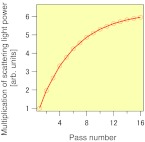
As a result of the optical system design, we can estimate the effect of the multi-pass TS system. Figure 4 shows the multiplication of the scattering light as a function of the pass number. This indicates that scattering light signals are increased by a factor of two for the double-pass configuration. For the sixteenth pass, the light scattering was about six times larger than the single-pass configuration.
Figure 4.
Scattering light power as a function of pass number.
EXPERIMENTAL RESULTS
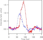
To evaluate the effect of the multiplication of the scattering light, the multi-pass system was installed in the GAMMA 10 system. This system can demonstrate double-pass scattering. Figure 5 shows the double- and single-pass TS signals. The integrated scattering signal of the double-pass configuration is about two times larger than that of the single-pass configuration. These results demonstrate the improvement in the data quality of the GAMMA 10 TS system and the feasibility of the proposed polarization-based multi-pass system.
Figure 5.
Double-(solid line) and single-pass (dashed line) TS signals by using a part of polarization-control multi-pass TS scheme.
SUMMARY
A novel multi-pass TS system configuration was proposed to improve the time resolution and accuracy of electron temperature measurements by the use of a polarization control technique. The configuration can realize perfect coaxial multi-passing at each pass. The number of round trips is not limited by the optical configuration but only by optical loss. We have demonstrated the multiplication of the scattering light by using a part of the polarization-control scheme in the GAMMA 10 system. The results showed that the integrated scattering signal of the double-pass configuration was about two times larger than that of the single-pass configuration, which is in good agreement with the design. These results demonstrates the improvement that can be gained in the data quality of the GAMMA 10 TS system and the feasibility of the proposed polarization-based multi-pass system.
ACKNOWLEDGMENTS
This work was supported by Grant-in-Aid for Young Scientists (B) (Grant No. 23760813) from MEXT and the NIFS Collaboration Research program (NIFS-KOAH025). The authors appreciate the assistance of R. Amakasu in preparing the manuscript.
Contributed paper, published as part of the Proceedings of the 19th Topical Conference on High-Temperature Plasma Diagnostics, Monterey, California, May 2012.
References
- Yoshikawa M. et al. , Plasma Fusion Res. 6, 1202095 (2011). 10.1585/pfr.6.1202095 [DOI] [Google Scholar]
- Barth C. J., Chu C. C., and Donne A. J. H., Rev. Sci. Instrum. 66, 501 (1995). 10.1063/1.1146330 [DOI] [Google Scholar]
- Schaeffer D. B. et al. , Rev. Sci. Instrum. 81, 10D518 (2010). 10.1063/1.3460626 [DOI] [PubMed] [Google Scholar]
- Dobele H. F. and Gindele K., Appl. Opt. 16, 2403 (1977). 10.1364/AO.16.002403 [DOI] [PubMed] [Google Scholar]
- Kantor M. Yu. et al. , Plasma Phys. Controlled Fusion 51, 055002 (2009). 10.1088/0741-3335/51/5/055002 [DOI] [Google Scholar]
- Hatae T., Naito O., Nakatsuka M., and Yoshida H., Rev. Sci. Instrum. 77, 10E508 (2006). 10.1063/1.2228347 [DOI] [Google Scholar]


