A device has been developed to optimize crystal-growth conditions by experiments in a single drop.
Keywords: crystal growth, single-drop optimization, Xtal-Controller
Abstract
A completely new crystal-growth device has been developed that permits charting a course across the phase diagram to produce crystalline samples optimized for diffraction experiments. The utility of the device is demonstrated for the production of crystals for the traditional X-ray diffraction data-collection experiment, of microcrystals optimal for data-collection experiments at a modern microbeam insertion-device synchrotron beamline and of nanocrystals required for data collection on an X-ray laser beamline.
1. Introduction
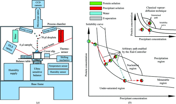
In order to overcome the widely recognized and vexing bottleneck that restrains applications of macromolecular crystallography, the discovery of optimal growth conditions for crystallization, advanced diagnostic tools are needed to obtain insights into the processes taking place in the crystallizing solution so that they can be used to adjust the solution conditions towards those conducive to better crystal growth. A device has been developed for just these purposes. In this device, the optimization experiment is conducted with a single microlitre-scale (2–10 µl) sitting drop in a vapour-diffusion device (Fig. 1 ▶ a) that is precisely temperature-controlled and humidity-controlled. Humidity control is especially important, not only to prevent uncontrolled evaporation of the sample drop but also to induce controlled evaporation to increase the concentration of the solution components in the sample drop in crystallization procedures. The composition of the actual mother liquor is altered by dispensing precipitant, water and other additives in picolitre increments, allowing free movement through the phase diagram (Fig. 1 ▶ b). The sample drop is continuously observed optically and, importantly, by means of an integrated dynamic light-scattering (DLS; Berne & Pecora, 1976 ▶; Brown, 1993 ▶) instrument. This device allows determination of the phase at any position in the diagram because the presence or absence of nuclei is monitored in situ by DLS (Dierks et al., 2008 ▶). The heart of the device is a microbalance (resolution of 0.1 µg), upon which the drop sits, which permits the determination of the evaporation rate (Klupsch et al., 2008b ▶) and the derivation of the concentrations of protein and precipitant components simultaneously throughout the course of the experiment. The device can be used for the optimization or scale-up of conditions obtained from a screening procedure, for the efficient production of crystals from seeds, for the modification of crystal solutions for cryoprotection, for the derivatization of crystals to support isomorphous replacement and anomalous diffraction phasing, for the addition of cross-linkers or ligands, for the growth of crystals for neutron diffraction, for the monitoring of enthalpy changes during crystal or complex formation and for the replication of a recorded optimized crystallization for the efficient production of additional crystals as needed.
Figure 1.
(a) Diagram of the Xtal-Controller. A gold mirror directs the DLS laser beam into the drop and guides the scattered light back to the detector. The sample is illuminated by a white-light LED source. The light passes through an optical diffusor to ensure smooth illumination. The droplet generators are positioned above the sample. To obtain a uniform temperature distribution, the body of the process chamber is made of aluminium and is thermally isolated by polyurethane foam. (b) Schematic depiction of navigation in the phase diagram made possible by the Xtal-Controller in comparison with classical vapour-diffusion experiments. The composition of the sample components, protein, precipitant and solvent, can be changed actively, quantified in situ and measured by DLS at the same time. In the three experiments reported here, water was the solvent. The various colouring patterns of the arrows indicate which dosage systems are active in achieving the desired ratios of water, precipitant and protein. The circles are pie charts that show ratios of the measured components, protein, solvent and precipitant, and indicate changes of the ratios within the sample drop at different positions in the phase diagram. Dashed coloured arrows indicate an alternating activity of two dosage systems or one dosage system along with evaporation. The grey and turquoise dashed arrow indicates evaporation and almost compensating water addition. The outcome of this is an extremely slow net weight loss caused by evaporation. A red and turquoise dashed arrow indicates an addition of precipitant, while loss of water caused by evaporation during this time is almost compensated by simultaneous addition of water. Consequently, precipitant solution replaces solvent bit by bit. In contrast to this, a common vapour-diffusion experiment is completely pre-defined by the concentration ratios of the components at the start of the experiment. Changing the path through the phase diagram requires alteration of the experimental setup.
The device includes several other important features. Up to four dosage systems (piezoelectric powered) can be coordinated to add ingredients to the sample drop or water to the drop to compensate for evaporation, all in a contact-free manner. The volume of a single dispensed droplet from a dosage system is set at 70 pl in the current design and each dosage system dispenses up to 10 000 droplets per second. The small volume of 70 pl relative to the sample drop minimizes convection effects within the sample drop caused by local concentration differences. The droplets are horizontally expelled and are slowed by air friction; they thus follow a parabolic course to the sample drop, reducing turbulence in the sample drop. Temperature changes resulting from the enthalpy produced by the reaction of the drop ingredients or by evaporation from the drop are measured with a resolution of 0.01 K (Klupsch et al., 2008a ▶). A microscope equipped with a CCD camera (spatial resolution of 2.5 µm) is provided for visualization of the sample volume and size determination of growing crystals. Microscopic crystal growth is monitored via a software tool that determines the morphological parameters of the growing crystal, such as surface area and perimeter, based on a convex hull and canny edge detection in the subsequent hull transform (Sonka et al., 2007 ▶). The system software collects, analyses and displays all data, controls the actuators of the instrument and permits fully remote operation.
2. Methods
In order to demonstrate the capabilities of this device, hereafter referred to as the Xtal-Controller, a series of example protein crystallizations were undertaken. The typical Xtal-Controller experiment used for these crystallizations was performed as follows. (i) The relative humidity in the process chamber was raised to 99.5%. (ii) A drop of protein solution was pipetted onto a siliconized glass cover slip and placed on the microbalance inside the process chamber. (At the elevated humidity levels under which these experiments were conducted, electrostatic charge on the siliconized cover slip is negligible.) (iii) The drop solution was checked by DLS to obtain an initial particle-size profile. (iv) Precipitant solution, with a composition either determined by initial screening trials or taken from the literature, was added to the sample in a predefined time-step program. During this phase of the experiment, the drop was monitored by DLS to detect initial nucleation (Streets & Quake, 2010 ▶; Vekilov, 2010 ▶). (v) Once nucleation had been detected, either more precipitant was added to produce a high number of nanocrystals or the addition of precipitant was stopped to obtain fewer but larger crystals. Regarding the former case, nanocrystals have become an important endpoint with the emergence of femtosecond X-ray nanocrystallography (Chapman et al., 2011 ▶). (vi) For larger crystals, once microscopically visible crystals had been detected, the growth rate was determined by processing images taken at defined time intervals. Further growth was maintained at a predefined rate primarily by adjusting the evaporation rate, with the addition of more protein being optional. (vii) Other additives and reagents were introduced via droplet generators as desired.
3. Results
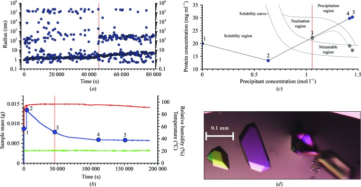
Fig. 2 ▶ summarizes the results for the first of three examples: the crystallization of crotamine, a 4.9 kDa neurotoxic protein from the venom of the Brazilian rattlesnake Crotalus durissus terrificus (in-house production; Ohler et al., 2010 ▶). The sample solution was initially scored by DLS (Fig. 2 ▶ a). DLS measurements from 0 to 5000 s revealed that the crotamine solution was polydisperse and it remained polydisperse upon addition of precipitant after 5000 s. However, as evaporation proceeded, the distribution of radii changed at 45 000 s and an increased signal from particles with a hydrodynamic radius of 200–300 nm was detected. We interpreted this signal as arising from nucleation or pre-nucleation events, which are indicated by the vertical red line (also shown in Figs. 2 ▶ b and 2 ▶ c) that marks the border between the metastable and nucleation regions in the phase diagram (Iwai et al., 2008 ▶). Fig. 2 ▶(b) shows addition of precipitant 5000 s after initiating the experiment and setting an evaporation rate to follow a predefined curve. This happened at an ammonium sulfate concentration of 1.066 M in the drop. [A metastable region in a supersaturated solution is considered as one where, based on experience, no nucleation is detectable via DLS but crystal growth is possible (Fig. 2 ▶ c).] The evaporation rate was slowed slightly after the detection of nuclei. When the microscope images indicated the appearance of crystals, the mass of the sample drop was placed on hold, which meant that the evaporation rate was adjusted to zero. The crystals were grown for 200 000 s (∼56 h) as shown in Fig. 2(d). Supplementary Video 11 provides a video representation monitoring the crystallization process that was constructed from screen images grabbed at roughly regular intervals over the course of the first half of the experiment. The entire controlled crystal-growth process was completed in about 2.5 d. Readers may want to pause the video and use the cursor bar below the parameter display to make a more detailed examination of the video.
Figure 2.
Crotamine crystallization. (a) Radius distributions obtained by DLS during the first 80 000 s of the crystallization process. The vertical red line indicates the moment when nucleation was detected by the emergence of a second distinct radius peak. (b) Plots of measured values of the sample mass (blue), humidity (red) and temperature (green) during the experiment. Until crystallization begins, the concentrations of protein and precipitant are known at every moment of the experiment. Positions 1–5 are used to show the positions in the phase diagram. Position 3 at 46 000 s corresponds to the start of the nucleation region. (c) Phase-diagram positions derived from the microbalance. Point 3 indicates the observed nucleation event when the system enters the nucleation region. Points 4 and 5 show the trajectory of protein and precipitant concentrations calculated based on weight changes caused by water evaporation had precipitation not begun. The grey curve indicates the estimated effective path of the protein concentration as it is reduced by phase transition and crystal growth. In contrast to this, the precipitant concentration can be precisely calculated since the precipitant remains dissolved. (d) Examples of the crotamine crystals produced.
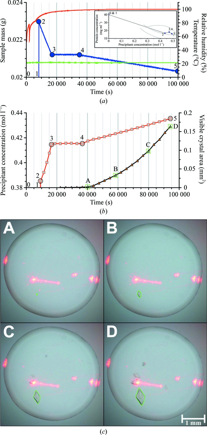
The second example is the crystallization of thaumatin from Thaumatococcus daniellii (Sigma T7638; de Vos et al., 1985 ▶) as summarized in Fig. 3 ▶. This example shows that precipitant size can be finely controlled to produce crystalline samples of a size, from millimetres to micrometres, ideal for the intended experiment. The nucleation zone can be reached by rapid addition of the precipitant and a controlled increase of the evaporation when DLS indicates the start of nucleation. Classical vapour-diffusion experiments typically start in under-saturated regions of the phase diagram. Depending on the crystallization conditions, a considerable amount of time may be required to pass through the under-saturated region of the phase diagram until the nucleation zone is reached. Increasing or reducing this time of passage appears to have no negative influence on the outcome of a crystallization experiment in our experience. In the Xtal-Controller, addition of precipitant within 10 min (fast addition) permits passage through the under-saturated region without harm to the experiment. DLS analysis of the radius distribution allows the experimenter to stop the addition of precipitant well before aggregation takes place. Too fast an evaporation rate, however, could lead to an undesirable protein-concentration gradient within the sample so that the DLS measurement volume might no longer be representative of the whole sample (Klupsch et al., 2003 ▶). Accordingly, after small crystals had been detected the evaporation rate was set to zero. Crystal growth was then analyzed and recorded using the image-processing algorithm mentioned above based on images taken at regular intervals. During this period, the initial growth rate was rather low, so in order to increase the crystal-growth rate the protein concentration was increased by deliberate evaporation. Four stages can be distinguished in Figs. 3 ▶(a) and 3 ▶(b): Phase 1 (0–8000 s; positions 0 and 1), where the drop mass was kept constant, without observing significant nucleation by DLS (not shown), Phase 2 (8000–18 000 s; positions 2 and 3), starting with the addition of the precipitant, where the evaporation rate was relatively high without visible crystals appearing, Phase 3 (18 000–37 000 s; positions 3 and 4), where the drop mass was kept constant and the first crystal appeared after about 22 000 s, and Phase 4 (37 000 s onwards; positions 4 and 5), where the evaporation rate was increased, accelerating the growth rate significantly. Note that high-humidity conditions must be actively maintained by the addition of water; decreasing the compensating addition of water permits an increase in the evaporation rate under finely controlled conditions. During this phase, the crystal-growth rate was followed by image processing as described above (Fig. 3 ▶ c). The green frame surrounding the crystal is the visualization of convex hull crystal recognition to calculate the visible crystal area. Fig. 3(b) shows examples from a series of images documenting crystal growth at 40 000 s (∼11 h), 55 000 s (∼15.5 h), 80 000 s (∼22 h) and 94 000 s (∼26 h). When no further crystal growth was detected, a droplet generator can add, for example, a 50%(v/v) glycerol/water mixture as a cryoprotectant treatment. Supplementary Video 21 provides a video representation monitoring the crystallization process that was constructed from screen images grabbed at roughly regular intervals over the course of the growth of microscale crystals of mistletoe lectin 1 (ML-1). ML-1 was chosen to permit comparisons with the next example and to appreciate differences in the crystallization programs developed to produce microscale and nanoscale crystals of the same protein.
Figure 3.
Thaumatin crystallization. (a) Plots of measured values of droplet mass (blue), humidity (red) and temperature (green) during the experiment. The initial precipitant concentration (0.385 mol l−1) was created very quickly at about 8000 s. The overlaid graph shows the derived phase diagram. The system is in a weak nucleation region, probably close to the metastable region. Numbers indicate the key positions where the composition of the sample has changed. (b) Plots of calculated precipitant concentration (red) and crystal size (black); the green triangles labelled A, B, C and D correspond to the camera images in (c). (c) Crystals at four different times. The perimeter of the crystal (green) was determined by the image-processing software to derive the crystal size. The passage of the DLS laser can clearly be seen.
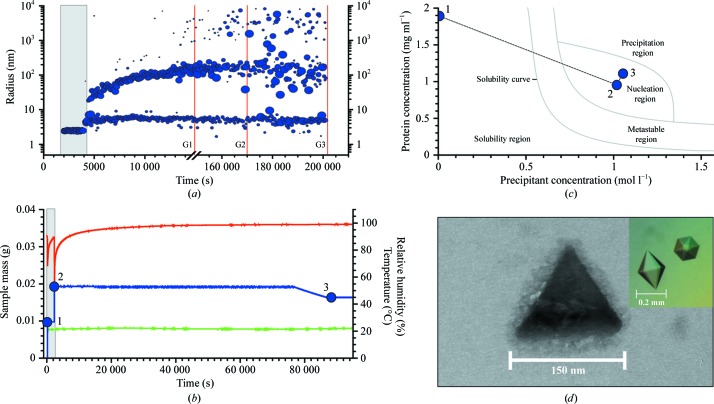
The third example, the production of nanocrystals of ML-I from Viscum album (in-house production; Meyer et al., 2008 ▶), is shown in Fig. 4 ▶. Crystal size was monitored by examining aliquots from the drop under the electron microscope. Three samples were taken until nanocrystals were observed in the third electron micrograph (Fig. 4 ▶ d). For comparison, the inset shows the typical shapes of crystals of the size usually used for diffraction study. Supplementary Video 31, which was constructed in a similar manner to those preceding, illustrates the monitoring of the process as the procedure developed for producing nanocrystals of this protein is executed.
Figure 4.
Mistletoe lectin I was used to produce crystalline nanoparticles. (a) Radius distributions obtained by DLS during the crystallization process. Note the break in the time axis. The lines G1, G2 and G3 indicate when aliquots were taken. (b) Plots of the measured values of the droplet mass (blue), the humidity (with a maximum value of 99%; red) and the temperature (green). Recording was not continued after the first aliquot was taken because of the balance disturbance. Three positions are numbered 1, 2 and 3. The grey area in both diagrams shows the initial phase before addition of the precipitant. (c) Positions in the phase diagram shortly before and after addition of the precipitant. These correspond to the three positions highlighted in (b). (d) Electron-microscopic image of a nanocrystal taken at time G3 revealed that cystalline nanoparticles with edge lengths of approximately 150 nm are present in the solution. Surprisingly, the crystalline particles are shaped as equilateral triangles concordant with tetrahedral geometry of the particles, whereas typical mistletoe lectin crystals observed by an optical microscope have a hexagonal bipyramidal morphology (insert). We have no reason to doubt that these nanocrystals would also grow in the same hexagonal bipyramidal morphology if the growth time were extended.
The Supplementary Material1 contains crystallization conditions for all examples.
4. Conclusions
In summary, the Xtal-Controller is a unique combination of diagnostic and manipulative techniques that allows direct real-time manipulation of crystallization-drop composition for the first time, reporting all relevant process data, e.g. the molarity of the protein or precipitant, and enabling an arbitrary and distinct path through the phase diagram towards directed crystal growth. The evaporation rate can be adjusted independently of the vapour pressure of the sample by adjusting the droplet-generation frequency, which has so far been impossible using conventional crystallization approaches. Strategies and procedures to apply the Xtal-Controller to search efficiently for initial nucleation conditions that can subsequently be optimized are under investigation.
Supplementary Material
Supplemetary Video 1. Millimetre-scale production of optimized crystals of crotamine.. DOI: 10.1107/S1744309112024074/wd5177sup1.avi
Supplementary Video 2. Production of microscale crystals of mistletoe lectin I.. DOI: 10.1107/S1744309112024074/wd5177sup2.avi
Supplementary Video 3. Production of nanoscale crystals of mistletoe lectin I.. DOI: 10.1107/S1744309112024074/wd5177sup3.avi
Supplementary material file. DOI: 10.1107/S1744309112024074/wd5177sup4.pdf
Acknowledgments
This work was supported by the Innovationsstiftung Schleswig-Holstein, by the Bundesministerium für Wirtschaft und Technologie, by the OptiCryst project of the European Commission under contract LSHG-CT-2006-037793 and by the Hamburg Ministry of Science and Research and Joachim Herz Stiftung as part of the Hamburg Initiative for Excellence in Research (LEXI). RH is supported by a Chinese Academy of Sciences Visiting Professorship for Senior International Scientists (grant No. 2010T1S6), by the DFG Cluster of Excellence ‘Inflammation at Interfaces’ and by the Fonds der Chemischen Industry. CB is supported by FAPEPS and DAAD (PROBAL 50754442) and grant No. CAPES 80563/2911 of the Brazilian Visiting Professorship Program. The authors thank Mônika A. Coronado from the Department of Physics, IBILCE/UNESP, São José do Rio Preto, Brazil for supplying crotamine and L. Redecke and the group of E. Mandelkow for the preparation of electron-microscopic images.
Footnotes
Supplementary material has been deposited in the IUCr electronic archive (Reference: WD5177).
References
- Berne, B. J. & Pecora, R. (1976). Dynamic Light Scattering. New York: John Wiley & Sons.
- Brown, W. (1993). Editor. Dynamic Light Scattering: The Method and Some Applications. Oxford: Clarendon Press.
- Chapman, H. N. et al. (2011). Nature (London), 470, 73–78.
- Dierks, K., Meyer, A., Einspahr, H. & Betzel, C. (2008). Cryst. Growth Des. 8, 1628–1634.
- Iwai, W., Yagi, D., Ishikawa, T., Ohnishi, Y., Tanaka, I. & Niimura, N. (2008). J. Synchotron Rad. 15, 312–315. [DOI] [PMC free article] [PubMed]
- Klupsch, T., Mühlig, P. & Hilgenfeld, R. (2003). Colloid Surf. A Physicochem. Eng. Aspects, 231, 85–102.
- Klupsch, T., Walter, A., Mühlig, P. & Hilgenfeld, R. (2008a). Colloid Surf. A Physicochem. Eng. Aspects, 318, 9–23.
- Klupsch, T., Walter, A., Mühlig, P. & Hilgenfeld, R. (2008b). Colloid Surf. A Physicochem. Eng. Aspects, 318, 24–44.
- Meyer, A., Rypniewski, W., Szymański, M., Voelter, W., Barciszewski, J. & Betzel, C. (2008). Biochem. Biophys. Acta, 1784, 1590–1595. [DOI] [PubMed]
- Ohler, M., Georgieva, D., Seifert, J., von Bergen, M., Arni, R. K., Genov, N. & Betzel, C. (2010). J. Proteome Res. 9, 2422–2437. [DOI] [PubMed]
- Sonka, M., Hlavac, V. & Boyle, R. (2007). Image Processing, Analysis and Machine Vision, 3rd ed. Toronto: Thomson Learning.
- Streets, A. M. & Quake, S. R. (2010). Phys. Rev. Lett. 104, 1–4. [DOI] [PMC free article] [PubMed]
- Vekilov, P. G. (2010). Nanoscale, 2, 2346–2357. [DOI] [PubMed]
- Vos, A. M. de, Hatada, M., van der Wel, H., Krabbendam, H., Peerdeman, A. F. & Kim, S.-H. (1985). Proc. Natl Acad. Sci. USA, 82, 1406–1409. [DOI] [PMC free article] [PubMed]
Associated Data
This section collects any data citations, data availability statements, or supplementary materials included in this article.
Supplementary Materials
Supplemetary Video 1. Millimetre-scale production of optimized crystals of crotamine.. DOI: 10.1107/S1744309112024074/wd5177sup1.avi
Supplementary Video 2. Production of microscale crystals of mistletoe lectin I.. DOI: 10.1107/S1744309112024074/wd5177sup2.avi
Supplementary Video 3. Production of nanoscale crystals of mistletoe lectin I.. DOI: 10.1107/S1744309112024074/wd5177sup3.avi
Supplementary material file. DOI: 10.1107/S1744309112024074/wd5177sup4.pdf


