

Abstract
Axonal degeneration after traumatic brain injury and nerve compression is considered a common underlying cause of temporary as well as permanent disability. Because a proper functioning of neural network requires phase coherence of all components, even subtle changes in circuitry may lead to network failure. However, it is still not possible to determine which axons will recover or degenerate after injury. Several groups have studied the pressure threshold for axonal injury within a nerve, but difficulty accessing the injured region; insufficient imaging methods and the extremely small dimensions involved have prevented the evaluation of the response of individual axons to injury. We combined microfluidics with atomic force microscopy and in vivo imaging to estimate the threshold force required to 1), uncouple axonal transport without impairing axonal survival, and 2), compromise axonal survival in both individual and bundled axons. We found that rat hippocampal axons completely recover axonal transport with no detectable axonal loss when compressed with pressures up to 65 ± 30 Pa for 10 min, while dorsal root ganglia axons can resist to pressures up to 540 ± 220 Pa. We investigated the reasons for the differential susceptibility of hippocampal and DRG axons to mechanical injury and estimated the elasticity of live axons. We found that dorsal root ganglia axons have a 20% lower elastic modulus than hippocampal axons. Our results emphasize the importance of the integrity of the axonal cytoskeleton in deciding the axonal fate after damage and open up new avenues to improve injury diagnosis and to identify ways to protect axons.
Introduction
Axonal degeneration can be triggered by different types of insults in the central nervous system (CNS) and the peripheral nervous system (PNS). Independent of the nature of the neuronal insult, morphological and pharmacological studies point to a convergent degenerative mechanism of which the hallmarks are compromised axonal transport, focal axonal swelling (FAS), and mitochondrial dysfunction (1–3). The axonal response to injury is a progressive degenerative process gradually evolving from focal axonal alteration to axonal disconnection. However, it is still not known if the axonal degenerative process can be stopped or delayed or how much damage axons can support and for how long before degeneration begins.
Most injury models and traditional histological methods only allow visualization of the sample before or after injury while detailed information on the histopathology that evolves during and shortly after axonal injury is left incomplete. In the CNS, studying the mechanism of axonal degeneration is even more challenging due to the difficulty in accessing the injured region and insufficient imaging methods. Although it is clear that the extent of axonal damage is directly related to the severity of unconsciousness, vegetative state, and survival of brain-injured patients (4–6), investigation of the mechanisms of degeneration of individual axons after physical injury has been limited.
To investigate the resistance of single axons to damage, we performed nerve constriction injuries in the nanoscale. We developed a model using atomic force microscopy (AFM) to apply gradual forces to locally compress axons of rat hippocampal or dorsal root ganglion (DRG) neurons grown in microfluidic chambers. Using subnanometric measurement techniques, we determined the pressure threshold for injury in hippocampal and DRG axons. Moreover, we compared the mechanical resistance, the reversibility of the damage, and the three-dimensional aspects of DRG and hippocampal axons under gradual impairment of axonal transport. Although DRG and hippocampal axons undergo similar morphological changes under compression, the response of each axonal type differs in intensity and time. DRG axons are more elastic and at least six-times more resistant to mechanical force than hippocampal axons.
Materials and Methods
Microfluidic chambers
The masters for the microfluidic chambers were manufactured in the McGill Nanotools Microfab (McGill University, Montreal, Quebec, Canada) and the chambers were prepared with polydimethylsiloxane (PDMS) using the Sylgard 184 Silicone elastomer kit (Dow Corning, Midland, MI) as previously described in Park et al. (7). The PDMS patterns were assembled on 35-mm glass-bottom dishes (MatTek, Ashland, MA) or on 25-mm glass coverslips (Warner Instruments, Hamden, CT) coated with Poly-D-Lysine (Sigma-Aldrich, St. Louis, MO).
Neuronal cultures
All animal experimentation was approved by the institutional animal care committee and conformed to the guidelines of the Canadian Council of Animal Care. Hippocampal and DRG neurons from Sprague Dawley rat embryos of either sex (Charles River, Wilmington, MA) were prepared as described previously in Lucido et al. (8) and Banker and Goslin (9) and added to microfluidic chambers. The chambers were disassembled by removing the PDMS three and eight days after plating from DRG and hippocampal cultures, respectively. Without the physical PDMS barrier between channels, hippocampal and DRG axons move and extend neurites toward other axons, remodeling the culture architecture and losing the parallel pattern. In DRG cultures, these changes were much more accentuated and were apparent one day after PDMS removal, whereas in hippocampal axons contact between axons grown in different channels was only observed 3–4 days after PDMS removal. To minimize remodeling and maintain the parallel organization of the axons in the cultures, DRG neurons were cultured at a density four-times lower than hippocampal neurons and were tested within 7–10 days in culture, whereas hippocampal axons were tested after 14–18 days in culture. These changes in culture density and age did not result in significant differences in the axonal response to injury applied with this model. Where indicated, cells were treated with vinblastine sulfate salt (Sigma-Aldrich) diluted in Neurobasal medium for 1 h, washed and immediately tested with AFM or fixed with 4% paraformaldehyde (Sigma-Aldrich) for immunohistochemical analysis or AFM imaging. Mitochondria were fluorescently labeled with Mitotracker Green FM (Invitrogen, Carlsbad, CA) and tubulin with Tubulin Tracker (Invitrogen).
Immunocytochemistry
Immunocytochemistry was performed as described previously in Lucido et al. (8) with mouse anti-tubulin (The Developmental Studies Hybridoma Bank, University of Iowa, IA), rabbit anti neurofilament (NFH, 200 kDa; Aves Lab, Tigard, OR), rabbit polyclonal anti-Tom20 (mitochondrial preprotein translocases of the outer membrane FL-145; Santa Cruz Biotechnology, Santa Cruz, CA), and Alexa 488 conjugated phalloidin (Invitrogen). The secondary antibodies used were Rhodamine Red anti-mouse IgG (Invitrogen) and Alexa Fluor 647 anti-rabbit IgG (Invitrogen). Samples were imaged using a Fluoview FV1000 laser scanning confocal microscope (Olympus, Richmond Hill, Ontario) with a 60× PlanApo oil-immersion objective on an inverted microscope.
Atomic force microscopy
Simultaneous compression and live imaging of single axons were performed on a Bioscope AFM (Veeco, Plainview, NY) mounted on an inverted optical microscope (Axiovert S100 TV; Carl Zeiss Canada, Toronto, Ontario, Canada) using a 100× objective (1.45 NA) and 1 K charge-coupled device camera (Photometrics, Tucson, AZ).
Two different compression experiments were performed:
In the first, a 20-μm polystyrene bead (Polysciences, Warrington, PA) was fixed (8) to the tip of silicon nitride probes (Cat. No. MSCT-AUHW microlevers; Veeco) with a nominal spring constant of k = 0.01 N/m and used to compress axons with controlled force ranging from 0.1–4 nanoNewton (nN) for different time periods.
In the second, tipless n-type silicon probes (Cat. No. CSC12; Mikromasch, San Jose, CA) with nominal spring constant of k = 0.03 N/m were used to apply constant force to axons. Cells were mounted onto a heated stage (Warner Instruments) and kept at 37°C with CO2 supply for the duration of the experiments. The AFM was used to localize and press the beaded or the tipless cantilever with submicrometer precision on top of axons. Images of the culture were taken every 30 s for 5–10 min before compression to detect mitochondrial movement and axonal viability, during compression to detect any change in the axon that could indicate damage, and for 10–30 min after compression release to analyze axonal recovery. To model compression, a series of 15 force-distance curves in static mode were taken at 30 s intervals on each axon. During data acquisition, loading forces of 0.3 nN were employed.
AFM imaging was performed on fixed axons with two different instruments, yielding similar results. To achieve the best resolution and image the thinnest axons with the lowest forces, the model No. MFP-3D-BIO AFM (Asylum Research, Santa Barbara, CA), mounted on a model No. IX-71 inverted optical microscope (Olympus), was used. Glass coverslips containing micropatterned neurons in PBS buffer were attached to a peak fluid cell using vacuum grease (Dow Corning). A 60× oil immersion objective with 1.45 NA (Olympus) was placed underneath the sample allowing optical access from the bottom and topographical access from the top of the sample.
The region of interest was located and aligned using a charge-coupled device camera. Silicon nitride probes (Cat. No. MSCT-AUHW microlevers, Veeco) were used to image under liquid. The deflection inverse optical lever sensitivity was calibrated in air and buffer before experimentation following Asylum Research protocols. The cantilever was oscillated at its first resonance frequency with amplitude of ∼0.6 nm. The deflection signal was low-pass-filtered and the resulting mean deflection signal was kept constant using a distance control feedback loop. The force applied to the sample throughout the scan was thus oscillatory and the average force (deflection) was set constant (∼10 pN). Images were acquired at 0.25 Hz with 2562 points per line along a distance of 20 μm2. Using this method, lateral force was reduced and the signal/noise ratio was increased. The spring constant of the cantilevers used was determined through theoretical calculations based on cantilever dimensions and material properties.
Data analysis
The Hertz model is the most commonly used model to determine the mechanical properties of cells (10–12). Using the Hertzian approximation, we present an estimation of the elastic moduli of axons using nanoindentation with AFM. Given the geometry of our system, where axons were compressed between a bead attached to the cantilever tip and the glass, the elastic compression of a cylinder by a sphere and a plane was modeled considering Hertzian effects (13).
The total compression is given by the total deformation δtotal, which is related to the deformation of the cylinder (axon) by the bead δbead on cylinder and the plane (glass) δplane on cylinder:
| (1) |
Modeling the underlying glass plane as a sphere with an infinite radius, the term accounting for the deformation induced by the plane is negligible. Using the method of Puttock and Thwaite (13), δbead on cylinder can be calculated as
| (2) |
where γ is the Poisson ratio of the axon or the bead, E is the Young's modulus of the material, F is the total force applied, e is the eccentricity of the ellipse of contact, and K and are complete elliptic integrals of the first and second class, respectively, with modulus e. In physical concepts, the force exerted by the bead is uniformly distributed along the contact plane. Therefore, the deformation, also called indentation from now on, is mainly an effect of the bead compression and follows:
| (3) |
The indentation data were analyzed using least-squares regression and fitted with the modified Hertz model for spherical indenter as appropriate (Eq. 3). Statistical differences were assessed using Student's t-test for continuous data and were accepted as significant at p < 0.05.
Results
Measuring the resistance of single DRG and hippocampal axons to compression
To investigate the axonal resistance to compression, we performed nerve constriction experiments in the nanoscale by using microfluidic chambers to grow and linearly extend DRG and hippocampal axons in parallel channels separated from cell bodies and dendrites (Fig. 1). The microfluidic chamber consists of a polydimethylsiloxane (PDMS) mold with a pattern of somatodendritic and axonal compartments connected by microgrooves adhered to a Poly-D-Lysine-coated coverslip (7). To mimic nerve constriction, we removed the PDMS and used the AFM to compress the axons grown in the microchannels. To follow axonal transport and viability, we fluorescently labeled mitochondria and imaged the axonal response to compression. The use of microfluidic chambers significantly facilitated the control and reproducibility of our data.
Figure 1.
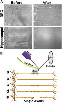
Experimental model of axonal compression. (A) Dissociated rat DRG (upper panels) and hippocampal (lower panels) neurons were grown in microfluidic chambers. Neurons were added to the somatodendritic -side of chambers and their axons extended into the axonal chamber through microgrooves (before). After 3–8 days in culture, microfluidic chambers were disassembled by removing the PDMS from the coverslip without damaging the cells (after). DRG and hippocampal neurons were kept in culture for 7 and 14 days, respectively, then the axons were tested with the AFM. Scale bar, 100 μm. (B) DRG and hippocampal axons grown in parallel channels were gradually compressed with sub-nanoNewton (nN) forces applied by a bead attached to the tip of the AFM cantilever (a). The axonal response to compression depended on the time and force applied and four distinct responses were identified after compression release: axons recovered their original state (b), stayed permanently deformed (c), entered a degenerative process with increasing formation of FAS (d), and finally resulted in axonal rupture (e).
Because axons grew in parallel, compression was applied at approximately the same distance from the soma on each axon (∼0.2 mm from the cell body chamber). In addition, the single axons or bundles grew in individual channels 50-μm apart from each other, improving the precise access of the AFM to the target axons. Controlled compression was performed with a bead ∼20 times larger than the axonal diameter attached to the tip of the AFM cantilever (8). Usage of a bead guaranteed that the observed axonal damage and response were due to compression forces and not due to piercing or damaging of the axonal membrane with the sharp tip of the AFM cantilever. The bead distributed the pressure along the axonal diameter, mimicking physiological nerve compression conditions. We compressed the axons by applying forces ranging from 0 to 7.5 nN. Topographic AFM images from the axons allowed the evaluation of the axonal height and width and indentation of the AFM cantilever according to the applied force. The average width of DRG axons and hippocampal axons tested were not significantly different (respectively, 1068 ± 429 nm and 1019 ± 476 nm). We used these data to estimate the area of contact between the bead and the axons and to calculate the applied pressure.
We found a direct relationship between compression forces and axonal injury. Compression with 550 ± 220 Pa led to the progressive collapse of hippocampal growth cones and reduction of mitochondrial signal and movement followed by axonal rupture, formation of retraction bulbs and neuronal degeneration (Fig. 2, and see Movie S1 in the Supporting Material). The axonal response to compression was the same when pressure was applied close to or distant from growth cones. By decreasing the pressure to 320 ± 150 Pa, FAS formed along the whole axon and remained even after pressure release, suggesting blockade of axonal transport also in regions distant from the compression point. Compression between 200 ± 90 and 130 ± 60 Pa resulted in local deformation of the axon under the compression point, which persisted after compression release (Fig. 2 A, arrows). All hippocampal axons tested only recovered their shape and mitochondrial movement if compressed with 65 ± 30 Pa or less for 10 min (Fig. 2 A). When hippocampal axons were compressed with 100 ± 50 Pa, only 40% of the axons tested recovered (Fig. 2 D). DRG axons could resist pressures up to 540 ± 220 Pa for 10 min and damaged axons were observed only with pressures in the range of 860 ± 350 Pa or higher (Fig. 2 B, and see Movie S2). These data indicate a significant difference between the mechanical resistance of hippocampal and DRG axons.
Figure 2.
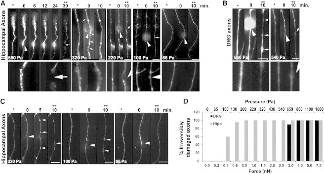
DRG axons are more resistant to compression than hippocampal axons. Higher pressures induce the formation of FAS and axonal deformities (arrows). (Arrowheads) Location of compression. The images are oriented such that the cell soma lies below the axonal segment shown in the panels. Scale bar, 10 μm. (A) Mitochondria were fluorescently labeled and single axons were compressed with a bead attached to the AFM cantilever with pressures ranging from 65 to 550 Pa for 10–30 min. Images taken before (∗), during, and after compression (∗∗) show that hippocampal axons do not recover axonal shape and mitochondria transport after compression release when compressed with pressures >65 Pa for 10 min. (Lower panels) 3× zoom of the compression region of the axons before compression and after compression release. Each panel represents one axon but at least 10 axons were tested in each condition with similar results. (B) DRG axons completely recovered after compression with 540 Pa for 10 min, but formed FAS along the whole axon when compressed with higher pressures (arrows). Each panel represents one axon but at least eight axons were tested in each condition with similar results. (C) The same compression experiment as in panel A was performed with hippocampal axons fluorescently labeled with Tubulin Tracker (Invitrogen), revealing the formation of FAS containing tubulin when pressure exceeds 65 Pa. Each panel represents one axon but at least eight axons were tested in each condition with similar results. (D) Quantification of the irreversibly damaged hippocampal or DRG axons after compression with different forces (±20%) and the corresponding estimated pressures (±40%) calculated based on the axonal diameter. Each bar represents the result of at least five axons tested under the same conditions.
Next, we investigated the effects of compression on the axonal cytoskeleton. We labeled axonal tubulin and compressed axons with different forces. We observed that compression of hippocampal axons with pressures <100 ± 50 Pa for 10 min causes a local blockade of axonal transport whereas higher pressures lead to multifocal blockade of axonal transport, with accumulation of tubulin and mitochondria in FAS distant from the compression point and distributed along the whole axon (Fig. 2 C). It is interesting to note that axons that recovered after compression injury only show FAS close to the compression point whereas all axons presenting with multiple FAS spots did not recover after compression release.
Hippocampal and DRG axons undergo different morphological changes due to impairment of axonal transport
The most characteristic morphological change that we observed during axonal compression was the formation of FAS. To better evaluate the formation of FAS close to the compression point on axons we changed the AFM cantilever to a tipless cantilever, which enabled us to apply compression to more than one axon at the same time (Fig. 3, A and B). Local increases of axonal width ≥10% or in axonal height ≥20% were considered as FAS. We found that ∼30% of hippocampal and DRG axons presented 1–3 small FAS before any treatment. As compression was applied, the number and size of FAS increased with the increase in compression time and force being applied (Fig. 3). Hippocampal axons formed more but smaller FAS than DRG axons (Fig. 3, C and D). In both types of axons, compressions with lower forces induce the formation of one or two FAS close to the compression point, which usually disappeared after compression release. However, when three or more FAS were formed along the axons, the axons did not recover their shape after compression release. The progressive formation of FAS in response to axonal injury highlights the importance of the development of early FAS markers for the application of potential therapeutic interventions, especially after brain trauma, as the number and size of FAS in the brain of injured patients is directly related to the degree of axonal damage and neuronal loss (4).
Figure 3.
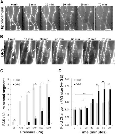
Progressive formation of FAS during axonal compression. (A) Mitochondria were fluorescently labeled and hippocampal axons were compressed for 60 min with 540 ± 220 Pa under a tipless AFM cantilever. (B) DRG axons were compressed with 1100 ± 440 Pa in the same conditions as in A. (Arrowheads) Compression site. (Arrows) Newly appearing FAS or increase in FAS size during compression. Soma lies below the axonal segment shown in the panels. Scale bar, 10 μm. (C) Plot showing the average number mean ± SE of FAS formed in each 60-μm axonal segment (n = 14) after compression of hippocampal and DRG axons for 10 min with different pressures (∗p < 0.001). (D) Increase in the size of FAS during compression of hippocampal and DRG axons for 60 min with 540 and 1500 Pa, respectively. The increase in FAS area was determined by setting a region of interest corresponding to each FAS at the end of compression, then using the National Institutes of Health software Image J (44), to measure the fluorescent area in each region of interest over the images acquired at different time points, enabling the calculation of the increase in the area of FAS during compression. Each bar corresponds to the average ± SE of the increase in the area of at least 20 FAS during compression (∗∗p < 0.05).
In healthy axons, axonal transport flows on microtubules and focal blockade of axonal transport and loss of microtubules leads to the accumulation of transported material and formation of FAS (2,14–16). Blockade of axonal transport can be achieved by compression, as we showed above, or by disruption of microtubules. To further characterize the formation of FAS during axonal injury we treated axons with increasing concentrations of vinblastine, which prevents polymerization of tubulin and induces depolymerization of formed tubules (17).
Next, we characterized the axonal morphological changes in three dimensions using AFM. Axons treated with vinblastine showed the same morphological features as axons compressed with high pressure. They formed multiple FAS along their length (Fig. 4 and see Fig. S1 in the Supporting Material) and the number and size of FAS increased with increasing vinblastine concentrations. This axonal injury had a strong resemblance to the one caused by the increase in compression time and force and resulted in a proportional degree of interruption in axonal transport (Figs. 3 and 4). In agreement with the compression data (Fig. 3), the shape and size of FAS in DRG axons were different from those in hippocampal axons, with FAS in DRG axons being remarkably larger than those of hippocampal axons (Fig. 4). To better evaluate the effects of multifocal blockade of axonal transport on the whole axonal cytoarchitecture, we estimated the volume of FAS in at least three segments along each axonal filament (Fig. 4 C).
Figure 4.
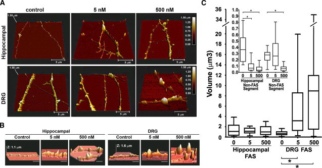
Progressive formation of FAS during gradual impairment of axonal transport. (A) Hippocampal and DRG axons not treated (control) or treated with 5 nM or 500 nM vinblastine for 1 h were fixed and imaged with the AFM. (B) Same as panel A, but focusing on FAS. Horizontal scale bar, 5 μm. (C) Box-and-whiskers plot showing the minimum and maximal volume of each FAS formed by hippocampal and DRG axons treated with increasing concentrations of vinblastine. (Inset) Box-and-whiskers plot of the minimum and maximal volume of an axonal segment between FAS (∗p < 0.0001). At least 23 axons were imaged and measured for each experimental condition.
We found that the increasing disruption of axonal transport with increasing vinblastine concentrations had different effects on the morphology of DRG and hippocampal axons. The volume of single FAS in DRG axons increased with increasing vinblastine concentrations whereas the volume of single FAS in hippocampal axons did not significantly change (Fig. 4 C), suggesting that DRG axons are more elastic than hippocampal axons and can accommodate a remarkably large local increase in diameter at FAS. We also evaluated the volume of axons in regions between FAS (non-FAS segment). With increasing vinblastine concentrations, hippocampal and DRG axons collapsed. In hippocampal axons, the volume of the non-FAS segment decreased at 5 nM vinblastine and in DRG axons at 500 nM vinblastine (Fig. 4 C, inset). To investigate the reason for the higher resistance of DRG axons to compression and to vinblastine effects, we investigated the composition and distribution of cytosolic components in axons with impaired transport.
The composition of the axonal cytoskeleton is critical to determine the axonal elasticity and, consequently, the degree of axonal susceptibility to damage. We analyzed the distribution of mitochondria, actin, neurofilament, and tubulin after blockade of axonal transport. During compression of DRG and hippocampal axons, we observed loss of mitochondrial labeling (see Fig. S2) and mitochondria accumulation in FAS (Fig. 2, A and B, and Fig. 3, A and B). Similarly, in vinblastine-treated axons, the distribution of mitochondria changed from uniform to a discontinuous punctate pattern, colocalizing with tubulin at FAS (see Fig. S3). In axons treated with vinblastine, actin concentrated between FAS and when it colocalized with FAS, actin formed cuplike structures apparently around FAS (see Fig. S3).
Neurofilaments and microtubules collapsed and accumulated at FAS (see Fig. S3). With increasing vinblastine concentration, there was a proportional increase in tubulin and neurofilament aggregation at FAS (see Fig. S3). The observed collapse of neurofilaments is likely due to neurofilament destabilization subsequent to microtubule collapse, because microtubules interact with neurofilaments (18,19) and vinblastine does not directly cause neurofilament disassembly (20). These data indicate that the composition of FAS is very similar in DRG and hippocampal axons and includes mitochondria and fragments of tubulin and neurofilaments, but not F-actin. It is possible that vesicles and other cellular components transported along axons might also accumulate in FAS.
After vinblastine treatment, DRG axons appeared to have more and larger FAS. This pattern coincides with our previous data obtained from compressed DRG axons, which formed larger FAS than hippocampal axons (Figs. 3 and 4). Given that the DRG and hippocampal axons tested had very similar caliber, larger FAS indicates that DRG axons may have a larger flow of transported material or higher content of tubulin or neurofilament. Because the structure of DRG axons after vinblastine treatment was more stable (Fig. 4), we decided to compare the amount of actin, tubulin, and neurofilament in DRG and hippocampal axons.
We found that DRG axons contain approximately seven times more neurofilament than hippocampal axons whereas actin and tubulin amounts are very similar in both axonal types (see Fig. S4). This is similar to previous results demonstrating that neurofilament/tubulin ratios are nearly threefold greater in PNS (axons from the sciatic nerve) than in CNS (axons from the optic nerve) axons (21). These differences in cytoskeleton composition are likely reflected in the axonal viscoelastic properties and resistance to injury. The composition of the axonal cytoskeleton is critical to determine the axonal elasticity and the degree of axonal susceptibility to damage because each component of the axonal cytoskeleton has different elastic properties. Neurofilaments are more flexible than actin, softer than microtubules, and can withstand large strains, providing cells with pliancy to accommodate small deformations while strengthening them when large stresses are applied (22).
Measuring the elasticity of individual axons
To determine whether the differential susceptibility of hippocampal and DRG axons to mechanical injury is indeed influenced by differences in elasticity due to differing cytoskeletal architecture, we evaluated the elastic modulus (EM) of live axons using AFM (Fig. 5 and see Fig. S4). The elastic modulus quantifies the tendency of a material to be nonpermanently (elastically) deformed when a force is applied to it, with a stiffer material having a higher EM. We calculated the axonal EM using the Hertz contact model with modifications to accommodate the geometry of the sample, considering the axon as a cylinder compressed by a sphere. We found that the EM of DRG axons was ∼20% lower than that of hippocampal axons at every indentation depth (p < 10−5; Fig. 5 B). The average EM variation strongly correlated with the depth of cantilever indentation and the EM constantly increased after 30% indentation in all axons tested (Fig. 5, A and B).
Figure 5.
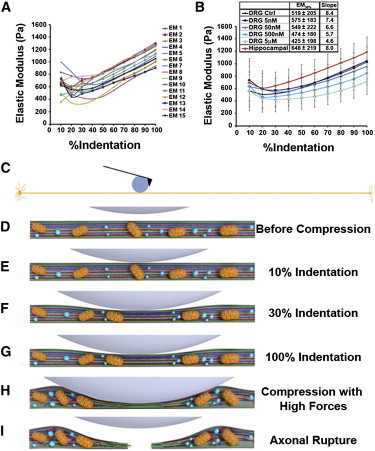
Elasticity of DRG and hippocampal axons. (A) Estimated EM as function of % indentation of 15 (EM 1–15) force-distance curves performed on one DRG axon at intervals of 30 s each, showing the high EM variability in the first 10–20% of indentation. The maximum (100%) indentation of the cantilever corresponds to approximately half of the axonal height. (B) Average EM ± SD of at least 10 hippocampal and 10 DRG axons treated or not with vinblastine (5 nM–5 μM). To compare the EM of different axons treated in different conditions, we considered the average EM at 30% of indentation (EM30%), when the value is very similar to the EM at 10–40% but presented lower variation. Moreover, at 30% indentation the axonal stiffening as a function of compression is not as evident as at 50% or higher indentations. (Inset) Increasing vinblastine concentrations decreased the average EM30% and the slope of the curve. (C) Model drawn to scale of a 0.6-mm-long and 1-μm-wide axon being compressed by a 20-μm bead attached to the AFM cantilever. (D–I) Model of axonal resistance to compression showing mitochondria (orange), tubulin (red), neurofilament (dark blue), actin (green), and vesicles (light blue).
Depth-dependent increases in the EM of biological samples have been reported by different groups suggesting that cell stiffness increases as compression increases, but the reasons for this effect have not been clarified (10). In general, the response of cells to applied force can be divided into two parts—the first, a mechanical response (23–25) consisting simply of the deformation of the cell's load-bearing structures, and the second, a biochemical signaling response, which potentially leads to most force-induced phenotypic changes (26–28). However, it is not yet understood in detail how strain (i.e., force) propagates through different intracellular structures (29). The intracellular environment is probably very dynamic in accommodating the compression forces, triggering different pathways and modifying the cytosolic architecture to avoid major damages. Therefore, understanding the origins of axonal stiffness is of fundamental importance to prevent axonal damage and consequent neuronal dysfunction.
To test whether the depth-dependent increase in axonal stiffness was caused by substrate or cytoskeleton resistance, we evaluated the EM of vinblastine-treated axons. The slope of the EM curve as a function of % indentation decreased proportionally with increasing vinblastine concentration (Fig. 5 B), confirming that cytoskeleton resistance is responsible for the depth-dependent increase in axonal stiffness. Treatment with 5 μM vinblastine significantly decreased the EM30% (p < 0.001) and the remaining slope in the EM curve of axons treated with 5 μM vinblastine is probably due to the stiffness of actin filaments that remain after vinblastine treatment (see Fig. S3 and Fig. 5).
Our hypothesis for the occurrence of differential axonal resistance to injury is that different axonal components play a major role in the mechanical resistance of axons, depending on the deformation of the axon (indentation depth) and on the component capacity to accommodate stress. This hypothesis is reinforced by our data indicating that the depth-dependent increase in the axonal EM is inversely proportional to the integrity of the cytoskeleton (Fig. 5). We propose that the high variation in EM observed at 10% indentation is caused by the AFM sensing axonal transport under the tip (Fig. 5 A), because at 10% indentation, the axonal lumen is not sufficiently reduced to impair axonal transport (Fig. 5 E). At moderate compression, the axonal lumen is reduced and mitochondria and larger vesicles start to accumulate, and the AFM tip then senses the resistance of the axonal cytoskeleton in addition to some axonal transport (Fig. 5 F).
As the compression deepens further, axonal transport becomes increasingly blocked, the variability of the axonal EM decreases (Fig. 5 A), and the axonal response to compression becomes more homogeneous—suggesting that the cantilever is compressing the axonal cytoskeleton (Fig. 5 G). Cytoskeleton resistance to compression is limited and, when hippocampal or DRG axons are compressed with larger forces (0.3 nN or 4 nN, respectively) for >10 min, irreversible changes take place and the cytoskeleton collapses (Fig. 5 H). Axonal transport is not restored after compression release and the axon is divided into two segments (Fig. 5 I). This suggests that the factor determining whether an axon will be severed or recover after damage is the elasticity and integrity of the cytoskeleton.
Discussion
The mechanism of axonal degeneration is quite similar in traumatic injuries and in chronic neurodegenerative diseases. The proposed model for axonal loss is that nerve insults lead to interruption of axonal transport, formation of FAS, increase in intra-axonal calcium levels, mitochondria dysfunction, and calcium-dependent cytoskeletal breakdown (for recent reviews, see Coleman (2) and Wang et al. (30)). Shortly after axonal injury, calcium influx has been shown to induce activation of proteases and the opening of the mitochondrial membrane permeability transition pore, resulting in pathologic swelling, loss of function, and local energy failure (1,2,31,32). Primary microtubules damage has also been shown to occur minutes after trauma (2,6,16,33). Together, these events are thought to represent the terminal events leading to axonal disconnection and degeneration. Axons are continually subjected to mechanical stimulation by external and internal forces but, when the forces exceed a certain threshold, the result is irreversible injury and axonal degeneration. Quantifying the forces is a first step in understanding the sequence of events that ultimately lead to the different stages of neuronal injury.
Several groups have studied the pressure threshold for injury of CNS and PNS axons. However, technical limitations have hindered the evaluation of single axonal responses to compression without the interference of the surrounding nerve environment. Indeed, the pressure threshold for axonal injury of PNS nerves was estimated at 30 mmHg (4 kPa), but compression with 20 mmHg (2.7 kPa) was shown to decrease blood flow inside PNS nerves and pressures of 30 mmHg (4 kPa) were described to impair axonal transport and cause a persistent increase in the pressure inside the nerve, edema, and nerve demyelination (34–37). In the CNS, the cornerstones of intensive care units include monitoring and management of patients' intracranial pressure (normally between 0 and 1.3 kPa) and therapy aiming at reducing intracranial pressure when it exceeds 2–2.7 kPa (38).
These limits are higher than the ones we found because they evaluate the consequences of pressure in the whole tissue whereas our study focused on the single axonal response. In the literature, there is no other study evaluating the response of single axons to injury caused by local compression with forces in the subnanoNewton scale with which we could compare our values. In addition, there is no model available to evaluate how the global intracranial pressure translates into local pressures on the different brain microenvironments and how elevated intracranial pressure might affect single axons. Interstitial fluid surrounding axons may act as a shock absorber or enhancer, and different situations such as trauma, edema, vascularization problems, brain tumors, stroke, infections, neurodegenerative diseases, or even surgery can significantly cause local increases in axonal pressure that may lead to degeneration.
Dynamic deformation of axons rarely leads to primary disconnection during brain trauma (1,4,39). Instead, disconnection occurs throughout the brain after focal axonal changes related to focal impairment of axonal transport, such as the FAS that we observed (Figs. 3–5). To understand the first steps involved in single axonal injury we used the AFM as a mechanical tool as well as an imaging instrument to locally compress DRG and hippocampal axons. We conclude that DRG axons are more resistant to compression and more elastic than hippocampal axons and we propose that differences in the cytoskeletal composition reflect in the viscoelastic properties of axons and play a significant role in axonal resistance to damage. Notably, the proportions and architecture of the main components of the axonal cytoskeleton change during development and myelination (40). Demyelination, a common event in different degenerative diseases (in the CNS such as multiple sclerosis or Leukodystrophies and in the PNS such as Guillain-Barré syndrome or Charcot-Marie-Tooth Disease), was shown to increase neurofilament density, decrease microtubules density, and slow axonal transport in the PNS and in the CNS (40). We propose that these physiological and pathological changes in cytoskeletal composition change the viscolelastic properties of axons and contribute to either increase or decrease the axonal resistance to damage.
Most studies on axonal degeneration focus on the biochemical signaling events triggered by axonal insults. Our results show that the mechanical properties of axons also play a significant role in deciding the axonal fate after damage. Moreover, we provide a new, to our knowledge, reproducible, and very precise model to study different parameters involved in axonal degeneration. The use of the AFM to compress and to give image axonal integrity can shed some light in different events involved in axonal loss such as cell signaling cascades, activity of mechanosensors, and electrostatic changes. Our model may be of particular interest to the recent debate on the foundation of nerve pulse propagation as an acoustic signal (41).
Some scientists claim that the action potential is actually an acoustic pulse or a soliton (42). Along the same lines, a very recent work demonstrates that two-dimensional pressure pulses indeed exist in lipid layers and are thermodynamic in its origin (43). The authors claim that two-dimensional pulses may play an important role in cell-cell and protein-protein communication (43). A deformation of the membrane using an AFM and subsequent variation in elastic properties should clearly alter the propagation of such waves, opening the door to test these hypotheses. The experimental approach presented here has the potential to stimulate a more fundamental quantitative and detailed investigation of the role of stress on neuronal function, damage, or growth and the propagation of action potentials in soft matter.
Conclusion
Axonal degeneration after traumatic brain injury or nerve compression caused by expansion of extraneural tissue is considered to be a common underlying cause of temporary and permanent disability. At the time of this writing, there is no model to study the effect of gradual axonal compression on isolated axons using live imaging technique. In existing models, central or peripheral nerve bundles are either axotomized or crushed, leading to a global axonal injury, glial response, and degeneration. To our knowledge, ours is the first model of axonal injury that allows control of the duration and force applied on a precise region of the axon, enabling injury reproducibility and the observation and comparison of individual axons injured equidistantly from the soma. We applied microfluidics, live cell imaging, and AFM to precisely calculate the force required to
-
1
disrupt the axonal transport without impairing axonal survival,
-
2
disrupt axonal transport and selectively induce axonal degeneration in isolated axons, and
-
3
calculate the elastic modulus of DRG and hippocampal axons.
The pressure threshold for injury in single axons from the DRG and hippocampus was measured, revealing that DRG axons are more elastic and more resistant to compression than hippocampal axons. Implications of these findings for the development of a model to study single local degeneration and drug screening in regenerative medicine are currently being explored.
Acknowledgments
We thank the reviewers for the constructive comments that significantly improved the discussion of this manuscript.
This work was supported by grants from the MNI-NeuroEngineering Fund (to D.R.C.) and from the Natural Sciences and Engineering Research Council of Canada, Canadian Institutes of Health Research, and Canadian Institute for Advanced Research (to P.G.). M.H.M. was an International Brain Research Organization Research Fellow. We thank Dr. Patricia Yam, Dr. Timothy Kennedy, Dr. Ben Barres, Jennifer Goldman, Dr. Ajit Dhaunchak, and Dr. Liliana Pedraza for helpful comments and discussion.
Footnotes
We dedicate this work to the memory of Dr. David R. Colman, who passed away suddenly on June 1, 2011.
Supporting Material
References
- 1.Maxwell W.L., Povlishock J.T., Graham D.L. A mechanistic analysis of nondisruptive axonal injury: a review. J. Neurotrauma. 1997;14:419–440. doi: 10.1089/neu.1997.14.419. [DOI] [PubMed] [Google Scholar]
- 2.Coleman M. Axon degeneration mechanisms: commonality amid diversity. Nat. Rev. Neurosci. 2005;6:889–898. doi: 10.1038/nrn1788. [DOI] [PubMed] [Google Scholar]
- 3.Weiss P., Hiscoe H.B. Experiments on the mechanism of nerve growth. J. Exp. Zool. 1948;107:315–395. doi: 10.1002/jez.1401070302. [DOI] [PubMed] [Google Scholar]
- 4.Adams J.H., Doyle D., McLellan D.R. Diffuse axonal injury in head injury: definition, diagnosis and grading. Histopathology. 1989;15:49–59. doi: 10.1111/j.1365-2559.1989.tb03040.x. [DOI] [PubMed] [Google Scholar]
- 5.Povlishock J.T. Traumatically induced axonal injury: pathogenesis and pathobiological implications. Brain Pathol. 1992;2:1–12. [PubMed] [Google Scholar]
- 6.Smith D.H., Meaney D.F. Axonal damage in traumatic brain injury. Neuroscientist. 2000;6:483–495. [Google Scholar]
- 7.Park J.W., Vahidi B., Jeon N.L. Microfluidic culture platform for neuroscience research. Nat. Protoc. 2006;1:2128–2136. doi: 10.1038/nprot.2006.316. [DOI] [PubMed] [Google Scholar]
- 8.Lucido A.L., Suarez Sanchez F., Colman D.R. Rapid assembly of functional presynaptic boutons triggered by adhesive contacts. J. Neurosci. 2009;29:12449–12466. doi: 10.1523/JNEUROSCI.1381-09.2009. [DOI] [PMC free article] [PubMed] [Google Scholar]
- 9.Banker G., Goslin K. Developments in neuronal cell culture. Nature. 1988;336:185–186. doi: 10.1038/336185a0. [DOI] [PubMed] [Google Scholar]
- 10.Costa K.D., Sim A.J., Yin F.C.P. Non-Hertzian approach to analyzing mechanical properties of endothelial cells probed by atomic force microscopy. J. Biomech. Eng. 2006;128:176–184. doi: 10.1115/1.2165690. [DOI] [PubMed] [Google Scholar]
- 11.Radmacher M., Tillmann R.W., Gaub H.E. From molecules to cells: imaging soft samples with the atomic force microscope. Science. 1992;257:1900–1905. doi: 10.1126/science.1411505. [DOI] [PubMed] [Google Scholar]
- 12.Mahaffy R.E., Park S., Shih C.K. Quantitative analysis of the viscoelastic properties of thin regions of fibroblasts using atomic force microscopy. Biophys. J. 2004;86:1777–1793. doi: 10.1016/S0006-3495(04)74245-9. [DOI] [PMC free article] [PubMed] [Google Scholar]
- 13.Puttock M.J., Thwaite E.G. Commonwealth Scientific and Industrial Research Organization; Melbourne, Victoria, Australia: 1969. Elastic Compression of Spheres and Cylinders at Point and Line Contact. 64. [Google Scholar]
- 14.Povlishock J.T., Christman C.W. The pathobiology of traumatically induced axonal injury in animals and humans: a review of current thoughts. J. Neurotrauma. 1995;12:555–564. doi: 10.1089/neu.1995.12.555. [DOI] [PubMed] [Google Scholar]
- 15.Maxwell W.L., Graham D.I. Loss of axonal microtubules and neurofilaments after stretch-injury to guinea pig optic nerve fibers. J. Neurotrauma. 1997;14:603–614. doi: 10.1089/neu.1997.14.603. [DOI] [PubMed] [Google Scholar]
- 16.Kilinc D., Gallo G., Barbee K.A. Mechanically-induced membrane poration causes axonal beading and localized cytoskeletal damage. Exp. Neurol. 2008;212:422–430. doi: 10.1016/j.expneurol.2008.04.025. [DOI] [PubMed] [Google Scholar]
- 17.Jordan M.A., Wilson L. Microtubules as a target for anticancer drugs. Nat. Rev. Cancer. 2004;4:253–265. doi: 10.1038/nrc1317. [DOI] [PubMed] [Google Scholar]
- 18.Bocquet A., Berges R., Eyer J. Neurofilaments bind tubulin and modulate its polymerization. J. Neurosci. 2009;29:11043–11054. doi: 10.1523/JNEUROSCI.1924-09.2009. [DOI] [PMC free article] [PubMed] [Google Scholar]
- 19.Kushkuley J., Chan W.K., Shea T.B. Neurofilament cross-bridging competes with kinesin-dependent association of neurofilaments with microtubules. J. Cell Sci. 2009;122:3579–3586. doi: 10.1242/jcs.051318. [DOI] [PubMed] [Google Scholar]
- 20.Mori H., Kurokawa M. Purification of neurofilaments and their interaction with vinblastine sulfate. Cell Struct. Funct. 1979;4:163–167. [Google Scholar]
- 21.Oblinger M.M., Brady S.T., Lasek R.J. Cytotypic differences in the protein composition of the axonally transported cytoskeleton in mammalian neurons. J. Neurosci. 1987;7:453–462. doi: 10.1523/JNEUROSCI.07-02-00453.1987. [DOI] [PMC free article] [PubMed] [Google Scholar]
- 22.Wagner O.I., Rammensee S., Janmey P.A. Softness, strength and self-repair in intermediate filament networks. Exp. Cell Res. 2007;313:2228–2235. doi: 10.1016/j.yexcr.2007.04.025. [DOI] [PMC free article] [PubMed] [Google Scholar]
- 23.Janmey P.A., Weitz D.A. Dealing with mechanics: mechanisms of force transduction in cells. Trends Biochem. Sci. 2004;29:364–370. doi: 10.1016/j.tibs.2004.05.003. [DOI] [PubMed] [Google Scholar]
- 24.Kasza K.E., Rowat A.C., Weitz D.A. The cell as a material. Curr. Opin. Cell Biol. 2007;19:101–107. doi: 10.1016/j.ceb.2006.12.002. [DOI] [PubMed] [Google Scholar]
- 25.Bausch A.R., Kroy K. A bottom-up approach to cell mechanics. Nat. Phys. 2006;2:231–238. [Google Scholar]
- 26.Orr A.W., Helmke B.P., Schwartz M.A. Mechanisms of mechanotransduction. Dev. Cell. 2006;10:11–20. doi: 10.1016/j.devcel.2005.12.006. [DOI] [PubMed] [Google Scholar]
- 27.Chien S. Mechanotransduction and endothelial cell homeostasis: the wisdom of the cell. Am. J. Physiol. Heart Circ. Physiol. 2007;292:H1209–H1224. doi: 10.1152/ajpheart.01047.2006. [DOI] [PubMed] [Google Scholar]
- 28.Geiger B., Bershadsky A. Exploring the neighborhood: adhesion-coupled cell mechanosensors. Cell. 2002;110:139–142. doi: 10.1016/s0092-8674(02)00831-0. [DOI] [PubMed] [Google Scholar]
- 29.Hoffman B.D., Crocker J.C. Cell mechanics: dissecting the physical responses of cells to force. Annu. Rev. Biomed. Eng. 2009;11:259–288. doi: 10.1146/annurev.bioeng.10.061807.160511. [DOI] [PubMed] [Google Scholar]
- 30.Wang J.T., Medress Z.A., Barres B.A. Axon degeneration: molecular mechanisms of a self-destruction pathway. J. Cell Biol. 2012;196:7–18. doi: 10.1083/jcb.201108111. [DOI] [PMC free article] [PubMed] [Google Scholar]
- 31.Beirowski B., Nógrádi A., Coleman M.P. Mechanisms of axonal spheroid formation in central nervous system Wallerian degeneration. J. Neuropathol. Exp. Neurol. 2010;69:455–472. doi: 10.1097/NEN.0b013e3181da84db. [DOI] [PubMed] [Google Scholar]
- 32.Barrientos S.A., Martinez N.W., Court F.A. Axonal degeneration is mediated by the mitochondrial permeability transition pore. J. Neurosci. 2011;31:966–978. doi: 10.1523/JNEUROSCI.4065-10.2011. [DOI] [PMC free article] [PubMed] [Google Scholar]
- 33.Tang-Schomer M.D., Patel A.R., Smith D.H. Mechanical breaking of microtubules in axons during dynamic stretch injury underlies delayed elasticity, microtubule disassembly, and axon degeneration. FASEB J. 2010;24:1401–1410. doi: 10.1096/fj.09-142844. [DOI] [PMC free article] [PubMed] [Google Scholar]
- 34.Lundborg G., Myers R., Powell H. Nerve compression injury and increased endoneurial fluid pressure: a “miniature compartment syndrome”. J. Neurol. Neurosurg. Psychiatry. 1983;46:1119–1124. doi: 10.1136/jnnp.46.12.1119. [DOI] [PMC free article] [PubMed] [Google Scholar]
- 35.Dahlin L.B., Rydevik B., Sjöstrand J. Changes in fast axonal transport during experimental nerve compression at low pressures. Exp. Neurol. 1984;84:29–36. doi: 10.1016/0014-4886(84)90003-7. [DOI] [PubMed] [Google Scholar]
- 36.Powell H.C., Myers R.R. Pathology of experimental nerve compression. Lab. Invest. 1986;55:91–100. [PubMed] [Google Scholar]
- 37.Keir P.J., Bach J.M., Rempel D.M. Guidelines for wrist posture based on carpal tunnel pressure thresholds. Hum. Factors. 2007;49:88–99. doi: 10.1518/001872007779598127. [DOI] [PubMed] [Google Scholar]
- 38.Ghajar J. Traumatic brain injury. Lancet. 2000;356:923–929. doi: 10.1016/S0140-6736(00)02689-1. [DOI] [PubMed] [Google Scholar]
- 39.Pierce J.E., Smith D.H., McIntosh T.K. Enduring cognitive, neurobehavioral and histopathological changes persist for up to one year following severe experimental brain injury in rats. Neuroscience. 1998;87:359–369. doi: 10.1016/s0306-4522(98)00142-0. [DOI] [PubMed] [Google Scholar]
- 40.Witt A., Brady S.T. Unwrapping new layers of complexity in axon/glial relationships. Glia. 2000;29:112–117. doi: 10.1002/(sici)1098-1136(20000115)29:2<112::aid-glia3>3.0.co;2-z. [DOI] [PubMed] [Google Scholar]
- 41.Heimburg T., Jackson A.D. On soliton propagation in biomembranes and nerves. Proc. Natl. Acad. Sci. USA. 2005;102:9790–9795. doi: 10.1073/pnas.0503823102. [DOI] [PMC free article] [PubMed] [Google Scholar]
- 42.Andersen S.S., Jackson A.D., Heimburg T. Towards a thermodynamic theory of nerve pulse propagation. Prog. Neurobiol. 2009;88:104–113. doi: 10.1016/j.pneurobio.2009.03.002. [DOI] [PubMed] [Google Scholar]
- 43.Griesbauer J., Bössinger S., Schneider M.F. Propagation of 2D pressure pulses in lipid monolayers and its possible implications for biology. Phys. Rev. Lett. 2012;108:198103. doi: 10.1103/PhysRevLett.108.198103. [DOI] [PubMed] [Google Scholar]
- 44.Abramoff M.D., Magalhaes P.J., Ram S.J. Image processing with ImageJ. Biophot. Int. 2004;11:36–42. [Google Scholar]
Associated Data
This section collects any data citations, data availability statements, or supplementary materials included in this article.