Abstract
A ring array provides a very suitable geometry for forward-looking volumetric intracardiac and intravascular ultrasound imaging. We fabricated an annular 64-element capacitive micromachined ultrasonic transducer (CMUT) array featuring a 10-MHz operating frequency and a 1.27-mm outer radius. A custom software suite was developed to run on a PC-based imaging system for real-time imaging using this device.
This paper presents simulated and experimental imaging results for the described CMUT ring array. Three different imaging methods—flash, classic phased array (CPA), and synthetic phased array (SPA)—were used in the study. For SPA imaging, two techniques to improve the image quality—Hadamard coding and aperture weighting—were also applied. The results show that SPA with Hadamard coding and aperture weighting is a good option for ring-array imaging. Compared with CPA, it achieves better image resolution and comparable signal-to-noise ratio at a much faster image acquisition rate. Using this method, a fast frame rate of up to 463 volumes per second is achievable if limited only by the ultrasound time of flight; with the described system we reconstructed three cross-sectional images in real-time at 10 frames per second, which was limited by the computation time in synthetic beamforming.
I. Introduction
A ring-shaped transducer array provides a geometry suitable for forward-looking intracardiac echocardiography (ICE) and intravascular ultrasound (IVUS) imaging [1], [2]. The ring aperture is capable of volumetric imaging without mechanical beam steering, while providing clearance in the center, which facilitates its integration with a guide wire in IVUS imaging or therapeutic tools in ICE applications. The absence of transducer elements in the center degrades the beam quality, but the full disk aperture resolution can be obtained by applying a proper weighting scheme [3], [4]. Recent efforts have led to successful fabrication of ring arrays despite the challenges in design and fabrication [5]–[8]. Some initial characterization and imaging results have also been reported [2], [9], [10].
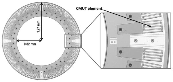
Capacitive micromachined ultrasonic transducers (CMUTs) have advantages over piezoelectric transducers in manufacturing the ring shape and integrating the transducer array with front-end electronics [11]. We fabricated a 64-element CMUT ring array using the poly-silicon sacrificial layer process with nitride thin plates and electrical through-wafer interconnects [12], and designed custom front-end electronics to improve the noise performance [13]. Fig. 1 and Table I show, respectively, an optical picture and the specifications of this device.
Fig. 1.
Optical picture of a capacitive micromachined ultrasonic transducer (CMUT) ring array.
TABLE I.
Capacitive Micromachined Ultrasonic Transducer Ring Array Specifications.
| Number of elements | 64 |
| Ring radius | 1.16 mm |
| Center frequency | 10 MHz |
| Transducer fractional bandwidth (−3 dB) | 80% |
| Element size | 80 × 100 μm |
Commercial medical imaging systems, such as Vivid 7 (GE Healthcare, Wauwatosa, WI) [14], [15], ACUSON SC2000 (Siemens Medical Solutions, Mountain View, CA), HD15 (Philips Healthcare, Andover, MA), and Model 1 (Volumetrics Medical Imaging, Durham, NC) [8], [9], can be used for volumetric real-time imaging with a ring array using conventional beamforming methods, simply by changing the probe geometry definition. Light et al. produced volumetric images in real-time at 30 volumes per second from a ring array, using a classic phased array approach and 16:1 receive-mode parallel processing using Model 1 [8]. However, it is difficult to use the commercial systems with nonconventional imaging techniques such as synthetic beamforming and Hadamard coding. In this study, we used a programmable PC-based imaging system (Verasonics Data Acquisition System, Verasonics Inc., Redmond, WA) to demonstrate the imaging performance of these nonconventional approaches. The data acquired by this system are transferred to a PC and then processed in real time by custom-developed software. Using multiple imaging methods, both simulated and experimental images were reconstructed and investigated, and the results are presented in this paper.
Section II briefly explains the imaging methods we used and the imaging results from simulations and experiments are presented in Sections III and IV, respectively. In Section V, we discuss practical limitations for real-time imaging.
II. Theory
In this study, we used flash, classic phased array (CPA), and synthetic phased array (SPA) beamforming methods. For SPA, aperture weighting and Hadamard coding were also explored to improve the image quality. The following subsections briefly explain these imaging methods and techniques. A theoretical comparison of these imaging methods is given in Table II.
TABLE II.
Theoretical Comparison of Imaging Methods.
| Flash | CPA | SPA | SPA with Hadamard coding | |
|---|---|---|---|---|
| Number of firings per frame | 1 | 16 471a | 64 | 64 |
| Maximum achievable frame rateb | 29 615 fps | 1.80 fps | 463 fps | 463 fps |
| Transmit/Receive focusing | Unfocused/Dynamic | Fixed/Dynamic | Dynamic/Dynamic | Dynamic/Dynamic |
| SNR gain from beamformingc | (54 dB)d | (54 dB) | (36 dB) | (54 dB) |
CPA = classic phased array; SPA = synthetic phased array; SNR = signal-to-noise ratio; NTX = number of transmit elements (64); NRX = Number of receive elements (64).
Beam sampling interval of 1° was assumed in both θ- and ϕ-directions, with viewing angle of 90° in θ and 180° in ϕ.
Maximum achievable frame rate was calculated based only on the ultrasound time of flight, assuming a 2.6-cm imaging depth.
SNR gain of the reconstructed image, over the SNR of a single-element pulse-echo A-scan.
Valid only in on-axis region.
A. Flash Imaging
Flash imaging is the simplest and fastest imaging method, in which we transmit only once to obtain one image frame. All 64 elements are fired at the same time without any delay, which results in an unfocused plane wave with a fully populated 2-dimensional array. However, because of the annular geometry, the flash transmit with a ring array generates an axially concentrated ultrasound beam. Therefore, flash imaging yields poor image quality, especially for off-axis targets. In receive, all 64 elements are used to obtain the image through conventional delay-and-sum beamforming operations.
B. Classic Phased Array Imaging
In each transmit event, all 64 elements are fired with different delays determined by the distance between the transducer element and the focal point. Therefore, the transmitted beam is steered to a desired direction and focused at the focal depth with narrow beam profile. Echo signals are received by all 64 elements, and processed for image reconstruction along the transmitted beam line through delay-and-sum operations. To obtain the whole image, as many beams are fired as the number of scan lines in the region of interest, and this limits the achievable frame rate significantly in volumetric imaging.
The transmit and receive apertures can be weighted separately to suppress the side lobes. However, the weighting scheme cannot be applied on the individual transmit-receive pairs for proper coarray formation [16]. As a result, for ring array geometry, CPA imaging is disadvantaged by a high side lobe level compared with SPA with appropriate aperture weighting.
C. Synthetic Phased Array Imaging
In the basic form of SPA imaging, a single element transmits and all 64 elements receive in each acquisition. After 64 firings, the A-scans from all 64 × 64 transmit-receive pairs are collected, upon which synthetic beam-forming is performed based on the round-trip delay from the transmit element to the field point and then to the receive element. The image for a field point r⃗ is calculated by
| (1) |
where Ai,j(t) is the received A-scan for the ith transmitter and the jth receiver at time t. τi(r⃗) and τj(r⃗) are the one-way propagation delays from the ith transmitter to the field point r⃗, and from r⃗ to the jth receiver, respectively.
The number of firings is significantly fewer than that in CPA, but this method suffers from a low SNR because of the single-element firing. Firing multiple elements in each acquisition, by tying neighboring elements together [1] or using coded excitation techniques, helps improve the SNR. In this study, we implemented one of the spatial coded excitation techniques, Hadamard coding, which is introduced later in this section. Recently, a synthesis technique by delay dithering with whole-array transmission was proposed by Hoctor et al. [17].
D. Aperture Weighting in SPA Imaging
One advantage of SPA is that each of the transmit-receive element pairs can be weighted for optimal coarray formation with the desired point spread function (PSF). Weighting the ring aperture with Norton weights results in a PSF of the form J1(R)/R, which corresponds to the PSF of a full disk aperture, where J1 is the first-order Bessel function [3], [4]. The Norton weight for the ith transmitter and the jth receiver is given by
| (2) |
where θi and θj are, respectively, the angular locations of the transmit and the receive elements.
Cosine apodization in the radial dimension helps suppress the side lobes, at the expense of widened main lobe [2], [18]. The weights for cosine apodization are
| (3) |
where
| (4) |
is the radius of the effective aperture, a is the radius of the ring array, and K is a parameter that we can adjust to trade off between main lobe width and side lobe level. Higher K results in lower side lobes, but a wider main lobe.
In the simulations and experiments presented in this paper, both Norton and cosine weightings were applied, with K = 0.5 for cosine weighting.
E. Hadamard Coding in SPA Imaging
Hadamard coding is one of the spatial pulse encoding techniques effective in increasing the SNR of SPA imaging without affecting its frame rate [19], [20]. In each of the 64 firings, all 64 elements are active simultaneously, with their pulse polarities encoded by 64 × 64 Hadamard matrix. The 64 pulses have the same polarity only in the first firing, and in the subsequent firings half of them are inverted. The same Hadamard matrix is used to decode the received echo signals, and the weighting schemes can be applied on the decoded data. The 64-element Hadamard coding scheme increases the SNR by 18 dB.
III. Simulations
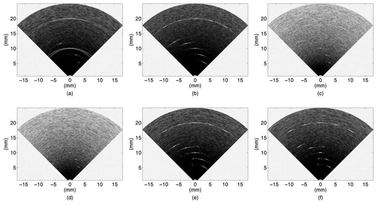
Imaging with a ring array was simulated for six different imaging methods: flash, CPA, basic SPA without aperture weighting or multi-element firing (SPA-0), SPA with aperture weighting (SPA-W), SPA with Hadamard coding (SPA-H), and SPA with both Hadamard coding and aperture weighting (SPA-HW). An ultrasound field simulation program, Field II [21], [22], was used to generate the simulated RF data, each of which contained white Gaussian noise with equal power to the experimentally measured noise. Ten point reflectors were assumed at (6 mm, 30°), (8 mm, 15°), (10 mm, 0°), (12 mm, −15°), (14 mm, −30°), (20 mm, −30°), (20 mm, −15°), (20 mm, 0°), (20 mm, 15°), and (20 mm, 30°) in the (R, θ) plane. Important simulation parameters are summarized in Table III.
TABLE III.
Simulation Conditions.
| Sampling frequency | 45 MHz |
| Transducer center frequency | 10 MHz |
| Transducer fractional bandwidth (−3 dB) | 80% |
| Attenuation | Not included |
| Image voxel size | 0.05 mm × 1° × 1° |
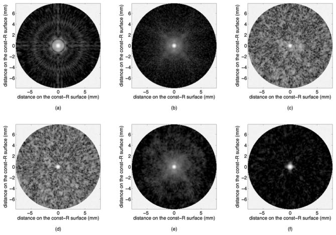
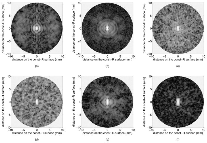
Fig. 2 presents the B-mode images reconstructed by our custom real-time imaging software. Flash imaging [Fig. 2(a)] is very poor in showing the off-axis targets because the ultrasound energy is concentrated along the axis, and even the on-axis targets show strong side lobes. SPA without Hadamard coding [Figs. 2(c) and 2(d)] suffers from low SNR, but Hadamard coding improves the SNR significantly [Figs. 2(e) and 2(f)]. SPA-H [Fig. 2(e)] achieves identical SNR to that of CPA [Fig. 2(b)]. Side lobe suppression resulting from aperture weighting is observed in the SPA-HW image [Fig. 2(f)], by comparing it to the SPA-H image [Fig. 2(e)]. In SPA-HW [Fig. 2(f)], as well as in SPA-W [Fig. 2(d)], Norton weighting was applied along with cosine weighting with K = 0.5. Constant-R images at 10 mm depth, through the target at (10 mm, 0°), are shown in Fig. 3. The SNR increase by Hadamard coding and side lobe suppression by weighting are clear from these images as well.
Fig. 2.
Simulated B-mode images of 10 point targets, shown in 40 dB dynamic range: (a) flash, (b) CPA with 10 mm focal depth, (c) SPA-0, (d) SPA-W (Norton weighting and cosine weighting with K = 0.5), (e) SPA-H, and (f) SPA-HW (Norton weighting and cosine weighting with K = 0.5).
Fig. 3.
Simulated constant-R images of an on-axis point target at 10 mm depth, shown in 40 dB dynamic range: (a) flash, (b) CPA with 10 mm focal depth, (c) SPA-0, (d) SPA-W (Norton weighting and cosine weighting with K = 0.5), (e) SPA-H, and (f) SPA-HW (Norton weighting and cosine weighting with K = 0.5).
IV. Experiments
A phantom with the same target locations as in the simulations was made using 150-μm fluorocarbon fishing wires [Fig. 4], and was imaged using different imaging methods. We programmed the Verasonics Data Acquisition System specifically for our ring array and the imaging methods we used, to acquire the reflection data, which are sent to our custom software for image reconstruction. The software reconstructs and displays three cross-sectional images—two B-mode planes orthogonal to each other and one constant-R plane—in real time. The frame rate varies with the imaging method and the imaging options, as will be discussed in more detail in Section V. Fig. 4 shows the experimental setup and Table IV lists the relevant experimental conditions.
Fig. 4.
Experimental setup and the fishing wire phantom used in the experiment.
TABLE IV.
Experimental Conditions.
| Sampling frequency | 45 MHz |
| Operation frequency | 10 MHz |
| CMUT bias voltage | −50 V |
| Pulse amplitude | ±30 V (bipolar pulse) |
| Phantom | 10 fluorocarbon wire targets with 150-μm thickness, immersed in vegetable oil |
| Image voxel size | 0.1 mm × 1° × 1° |
CMUT = capacitive micromachined ultrasonic transducer.
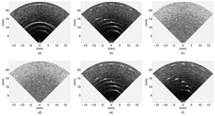
Experimental B-mode images and constant-R images are illustrated in Figs. 5 and 6, respectively, for the six imaging methods we tested. The presented B-mode plane is perpendicular to the wires, and the constant-R images are shown at 13 mm depth, where the nearer on-axis wire target (target 3 in Fig. 4) is located. These images look different than the simulated images because the experimental targets are not point reflectors, but wires with a thickness in the order of the ultrasound wavelength. Two distinct reflections from the front and the back sides of the wire are seen in the B-mode images. In the constant-R images, the wire looks longer in the longitudinal direction.
Fig. 5.
Experimental B-mode images of the fishing wire phantom, shown in 40 dB dynamic range: (a) flash, (b) CPA (offline) with 13 mm focal depth, (c) SPA-0, (d) SPA-W (Norton weighting and cosine weighting with K = 0.5), (e) SPA-H, and (f) SPA-HW (Norton weighting and cosine weighting with K = 0.5).
Fig. 6.
Experimental constant-R images of an on-axis wire target at 13 mm depth, shown in 40 dB dynamic range. (a) flash, (b) CPA (offline) with 13 mm focal depth, (c) SPA-0, (d) SPA-W (Norton weighting and cosine weighting with K = 0.5), (e) SPA-H, and (f) SPA-HW (Norton weighting and cosine weighting with K = 0.5).
As was also observed in the simulated images, the flash images [Figs. 5(a) and 6(a)] have poor image quality, especially for off-axis targets, and the SPA-0 images [Figs. 5(c) and 6(c)] show low SNR. The effect of weighting is not clearly seen in the SPA-W images [Figs. 5(d) and 6(d)] because of the low SNR. However, with Hadamard coding [Figs. 5(e) and 6(e)], the SNR increases up to a level comparable to that of CPA [Figs. 5(b) and 6(b)], and the effect of weighting becomes clear [Figs. 5(f) and 6(f)]. One point to note here is that the CPA images [Figs. 5(b) and 6(b)] were reconstructed offline, because our data acquisition system could not handle the large number of beams required to scan the volume in real-time.
Table V presents the SNR measured from experimental A-scans and images. The SNR gain from beamforming represents how much improvement in SNR is achieved by beamforming, calculated by subtracting the single-element pulse-echo SNR, from the final image SNR. The measured SNR gain from beamforming shows good agreement with the theoretical expectations.
TABLE V.
Summary of Signal-to-Noise Ratio (SNR, in Decibels) for Different Imaging Methods.
| Measured A-scan SNRa | Measured image SNRa | Measured SNR gain from beamforming | Theoretical SNR gain from beamforming | |
|---|---|---|---|---|
| Flash | 14 | 34 | 53 | 54 |
| CPA | 14 | 35 | 54 | 54 |
| SPA-0 | −19b | 19 | 38 | 36 |
| SPA-W | −19b | 18 | 37 | 35 |
| SPA-H | −6b | 33 | 52 | 54 |
| SPA-HW | −6b | 34 | 53 | 53 |
CPA = classic phased array; SPA-0 = basic synthetic phased array (SPA) without aperture weighting or multi-element firing; SPA-W = SPA with aperture weighting; SPA-H = SPA with Hadamard coding; SPA-HW = SPA with both Hadamard coding and aperture weighting.
For SNR measurements, we defined a signal window and a noise window on the A-scan or on the reconstructed image. The signal window enclosed the echo signal from the on-axis target at 13 mm depth, and the noise window was defined outside the echo signal window where the signal power is due to electronic noise alone. The signal and the noise amplitudes were then measured by calculating the rms of the A-scan or the image amplitude in the signal and the noise windows, respectively.
SNR values smaller than 0 dB were measured after averaging over multiple data sets.
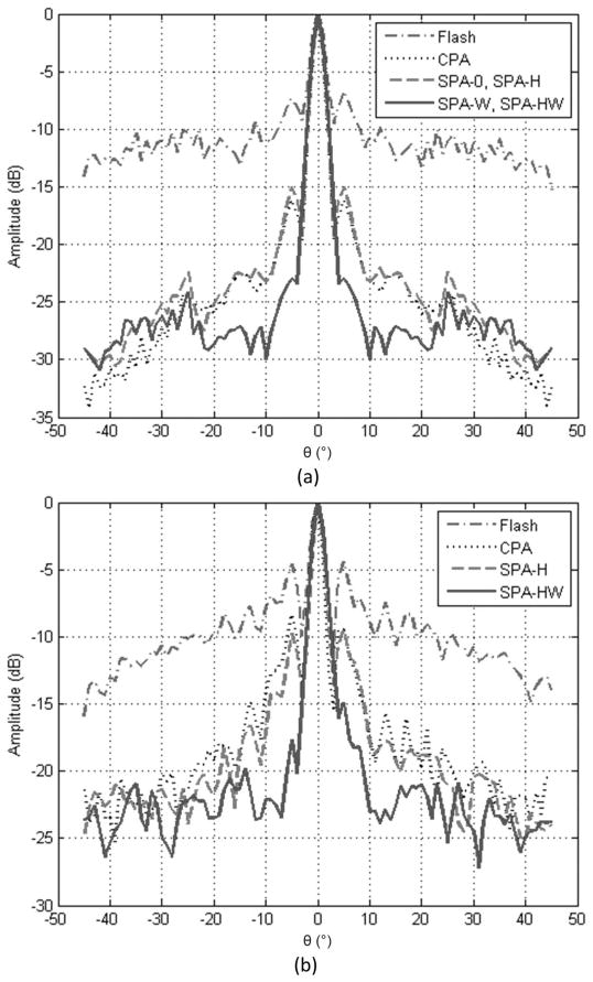
Normalized lateral line scans through an on-axis target from both simulations and experiments are plotted in Figs. 7(a) and 7(b), respectively, for different imaging methods. Here, the lateral line scans were compounded over a 1-mm axial depth to include most of the side lobe energy. The main lobe widths and the side lobe levels are calculated from these plots and presented in Table VI. The side lobe level is lower in simulations than in experiments because an ideal point target was used in PSF simulations instead of a wire target. All six imaging methods show a similar axial resolution of 95 μm in full-width at half-maximum (FWHM).
Fig. 7.
(a) Simulated lateral point spread functions for an on-axis point target at 10 mm depth. (b) Lateral line spread functions (LSFs) from experiments, for the on-axis wire target at 13 mm depth. Because Hadamard coding does not affect the image other than lowering the noise floor, the LSFs for SPA-0 and SPA-W are not included in (b) to simplify the figure. The image data were compounded over 1 mm axial depth in both (a) and (b), to include most of the side lobe energy.
TABLE VI.
Lateral Resolutions and Side Lobe Levels (Calculated from Lateral Line Scans Compounded Over 1 mm Axial Depth).
| Imaging method | Simulation (point target)
|
Experiment (wire target)
|
||||
|---|---|---|---|---|---|---|
| FWHM (°) | Averaged side lobe level (dB)a | Peak of the first side lobe (dB) | FWHM (°) | Averaged side lobe level (dB)a | Peak of the first side lobe (dB) | |
| Flash | 3.81 | −11.17 | −7.34 | 3.70 | −9.99 | −4.60 |
| CPA | 2.58 | −25.06 | −16.19 | 2.81 | −17.99 | −8.36 |
| SPA-0 and SPA-Hb | 2.67 | −24.04 | −15.03 | 2.85 | −19.20 | −9.73 |
| SPA-W and SPA-HWc | 3.00 | −27.32 | −23.01 | 3.39 | −22.62 | −17.71 |
FWHM = full-width at half-maximum; CPA = classic phased array; SPA-0 = basic synthetic phased array (SPA) without aperture weighting or multi-element firing; SPA-H = SPA with Hadamard coding; SPA-W = SPA with aperture weighting; SPA-HW = SPA with both Hadamard coding and aperture weighting.
Averaged from the first side lobes to ±45°.
SPA-0 and SPA-H give identical results in simulation without noise. In the experiment, the numbers are from SPA-H.
SPA-W and SPA-HW give identical results in simulation without noise. In the experiment, the numbers are from SPA-HW.
Fig. 8 shows cross-sectional images of an ex vivo chicken heart, imaged using SPA-HW. To increase the SNR, six frames were averaged without a significant loss of frame rate, because the SPA frame rate is mostly limited by the computational load, not by the data acquisition. The original frame rate of 10 frames per second (fps) dropped to 8.5 fps after averaging. The B-mode images [Figs. 8(a) and 8(b)] are real-time images, but the constant-R image [Fig. 8(c)] was processed offline for compounding over a 1 mm axial depth, to show the tissue with better contrast. The supplemental video shows 80 frames of these cross-sectional images (
 ).
).
Fig. 8.
Three cross-sectional images of a chicken heart, imaged using SPA-HW. Six frames were averaged to improve signal-to-noise ratio. (a) and (b) Two B-mode images orthogonal to each other. (c) Constant-R image compounded over 1 mm axial depth, from R = 10.0 mm to R = 11.0 mm.
V. Real-Time Imaging Considerations
Besides the ultrasound time of flight, there exist practical limitations which lower the achievable frame rate. They dominate the image acquisition time of our current system, and the actual frame rate we obtain is far slower than the theoretical limit.
Data transfer rate is one limitation that affects all of the imaging methods. With 45-MHz sampling from 64 channels and 2 bytes per sample, 5.76 GB of data are acquired every second. However, the data transfer rate of the PCI-Express interface connecting the Verasonics Data Acquisition System to the host PC is only 1.2 GB/s. It lowers the achievable frame rate by a factor of 4.8 from the numbers in Table II.
The frame rate of SPA is further limited by its computational load. The gold-standard beam pattern of SPA with dynamic focusing in both transmit and receive is obtained at the expense of immense computational load, dominated by delay-and-sum operations and Hilbert transforms. They represent 75% and 25% of the whole computation time, respectively, in reconstructing the three cross-sectional images in Fig. 8. Both Hadamard decoding and aperture weighting take negligible time. Our software consumes 3 clock cycles for a delay-and-sum operation, and it results in 10 fps for the three cross sections, using two quad-core (8 virtual cores with hyper-threading) 3-GHz CPUs (Intel Xeon Processor X5570, Intel Corporation, Santa Clara, CA).
Reconstructing fewer voxels helps reduce the computational load in delay-and-sum, but results in a reduction in the image resolution or the field of view. We can also decrease the number of A-scans involved in beam synthesis to proportionally reduce the number of operations in both delay-and-sum and Hilbert transforms. A method implemented in our software is to discard A-scans with low weights. Table VII summarizes the improvement in frame rate achieved by reducing the number of A-scans and the number of voxels. By discarding 2536 A-scans out of 4096, with weights below 0.5 after Norton weighting and cosine weighting with K = 1.0, the main lobe width in lateral PSF widens by 10% in terms of FWHM and the integrated side lobe level increases by 2 dB. However, it more than doubles the frame rate when displaying three cross-sectional images, each with 22 801 voxels. The SNR loss resulting from discarding those A-scans is about 2 dB. Another approach which finds an optimal set of even fewer A-scans based on the spatial frequency of transmit-receive pairs has also been proposed [1].
TABLE VII.
Measured Frame Rates (in Frames per Second) for Synthetic Phased Array Imaging.
| 22 801 voxels per plane
|
10 201 voxels per plane
|
|||||
|---|---|---|---|---|---|---|
| 3 planes | 2 planes | 1 plane | 3 planes | 2 planes | 1 plane | |
| Not discarding any A-scans (using all 4096 A-scans) | 9 | 12 | 20 | 17 | 21 | 28 |
| Discarding 1568 A-scans with weights less than 0.1 | 13 | 18 | 27 | 23 | 28 | 35 |
| Discarding 2048 A-scans with weights less than 0.3 | 16 | 21 | 31 | 27 | 33 | 40 |
| Discarding 2536 A-scans with weights less than 0.5 | 20 | 26 | 35 | 32 | 38 | 45 |
In these experiments, Norton weighting and cosine weighting with K = 1.0 were applied.
To save the time taken in the Hilbert transform, which involves a direct and an inverse Fourier transform, we can choose a faster approximate algorithm for obtaining in-phase and quadrature components of the signal, such as the direct sampling process [23], Hilbert filter method, or the quadrature demodulation method [24]. In two SPA experiments reconstructing one image plane and three image planes, with about 20 000 voxels per plane, adopting the direct sampling process increased the frame rate by 25% and 10%, respectively. The improvement is greater when fewer voxels are reconstructed, because the Hilbert transform represents a larger part of the total computation time.
A more straightforward way to speed up the computation is to use more powerful hardware. It has been reported that beamformers implemented with a GPU [25] or an FPGA [26] improve the ultrasound imaging system performance. New software performing computations on a GPU platform is under development, and an FPGA-based beamformer is also under consideration for our system.
As mentioned in the previous section, the experimental CPA images were reconstructed offline. Standard CPA imaging requires 16 471 beams to cover a 90° viewing angle with 1° resolution in both θ- and ϕ-directions. With this many beams and an imaging depth of 2.6 cm, the raw A-scan data amount to 3.24 GB per frame and the maximum achievable frame rate is limited by data transfer rate to 0.375 fps, which is already too slow for real-time imaging. In addition, the sequencer memory of our data acquisition system limited the maximum number of beams we can transmit to about 2000. Consequently, in CPA experiments, we divided the data acquisition into 9 sets, stored the A-scans in files, and then processed the data offline for image reconstruction. Multi-line acquisition and parallel beamforming techniques can be adopted to overcome these limitations in CPA imaging [27]–[29].
In Table VIII, maximum achievable frame rates of flash, CPA, and SPA imaging limited by individual factors are calculated for reconstructing three cross-sectional images with total of 60 333 voxels and a 2.6-cm imaging depth, as in Fig. 8.
TABLE VIII.
Frame Rate Limited by Individual Factor.
| Limiting factor | Flash | CPA | SPAa |
|---|---|---|---|
| Data acquisition rate (fps) | 29 615 | 1.80 | 463 |
| Data transfer rate (fps) | 6170 | 0.375 | 96.4 |
| Computational load (fps) | 737 | 9.85 | 11.5 |
| Bottleneck | Computation | Data transfer | Computation |
CPA = classic phased array; SPA = synthetic phased array.
Hadamard coding and weighting do not affect the frame rate of SPA.
VI. Conclusion
In this study, we demonstrated volumetric ultrasound imaging with a CMUT ring array using various imaging methods. Flash, CPA, and SPA with and without Hadamard coding and aperture weighting were simulated and experimentally implemented. The experimental results are in good agreement with simulations, as well as with the theory. Flash imaging results in a poor image quality, but it is fast and might be useful in some applications, including on-axis target detection and depth measurement. CPA is the most widely used method in commercial systems, with good resolution and SNR. However, it suffers from high side lobes as a result of the ring geometry. Also, the large number of beams required in volume scan makes real-time imaging difficult, unless we adopt a technique such as parallel beamforming to reduce the number of beams. SPA has an advantage in that Norton and cosine weighting schemes can be applied to improve the beam profile and suppress the side lobes. The low SNR is a critical drawback of this method, but spatial coded excitation can help increase the SNR of SPA. In this paper, we experimentally demonstrated that an SNR comparable to that of CPA can be achieved using the Hadamard coding technique on SPA.
SPA imaging, when combined with Hadamard coding and aperture weighting, gives the best option for real-time volumetric imaging with a ring array. Compared with CPA, it yields a comparable SNR and a better beam profile, with suppressed side lobes and dynamic focusing in both transmit and receive, at a significantly higher frame rate. Using this method, we successfully displayed three cross-sectional images of a chicken heart at 10 fps, and could achieve up to 45 fps without significant loss of image quality for displaying one cross-sectional image with a reduced number of voxels and A-scans. In SPA imaging with the described system, the bottleneck limiting the frame rate is the immense computational load required in synthetic beamforming. Our current efforts to improve the computational speed include utilizing a GPU and an FPGA for beamforming operations [25], [26]. New imaging methods for faster imaging, for example, CPA with multiline acquisition (CPA-MLA) [27]–[29] and flash imaging with multiple angles [30], are also being implemented.
Supplementary Material
Acknowledgments
We thank the Stanford Nanofabrication Facility (Stanford, CA), a member of National Nanotechnology Infrastructure Network, for the CMUT fabrication, and National Semiconductor (Santa Clara, CA) for their support in the design and fabrication of the IC. We also thank Verasonics Inc. for providing technical support.
This work was supported by the National Institutes of Health under grants HL67647 and CA134720. J. W. Choe was supported by the Kwanjeong Educational Foundation (Seoul, Korea).
Biographies

Jung Woo Choe received the B.S. degree in 2005 from Seoul National University (SNU), Seoul, Korea, and the M.S. degree in 2008 from Stanford University, Stanford, CA, both in electrical engineering. Currently, he is pursuing a Ph.D. degree in electrical engineering at Stanford University. He was awarded the General Electric Fellowship while at SNU and the Kwanjeong Educational Foundation Fellowship from 2006 to 2011.
He worked as a programmer for Spire Technology Inc., Anyang, Korea, from 2002 to 2003, and for NHN Cooperation, Seoul, Korea, from 2003 to 2005. Further, he held an internship position in the SRAM design group at Sun Microsystems, Santa Clara, CA, in 2007. He is now working as a research assistant in the Edward L. Ginzton Laboratory, Stanford University. His research interests include the design and implementation of real-time volumetric ultrasound imaging systems for capacitive micromachined ultrasonic transducer (CMUT) arrays, and software development for those systems.

Ömer Oralkan (S’93–M’05–SM’10) received the B.S. degree from Bilkent University, Ankara, Turkey, in 1995; the M.S. degree from Clemson University, Clemson, SC, in 1997; and the Ph.D. degree from Stanford University, Stanford, CA, in 2004, all in electrical engineering.
Dr. Oralkan was a Research Associate from 2004 to 2007 and then a Senior Research Associate from 2007 to 2011 in the Edward L. Ginzton Laboratory at Stanford University; he was an Adjunct Lecturer from 2009 to 2011 in the Department of Electrical Engineering at Santa Clara University, Santa Clara, CA. Currently, he is an Associate Professor of Electrical and Computer Engineering at North Carolina State University, Raleigh, NC. His current research focuses on developing devices and systems for ultrasound imaging, photoacoustic imaging, image-guided therapy, biological and chemical sensing, and ultrasound neural stimulation.
Dr. Oralkan authored more than 120 publications and received the 2002 Outstanding Paper Award of the IEEE Ultrasonics, Ferroelectrics, and Frequency Control Society. He is a Senior Member of the IEEE and serves on the Technical Program Committee of the IEEE Ultrasonics Symposium.
Amin Nikoozadeh received the B.S. degree from Sharif University of Technology, Tehran, Iran, in 2002; the M.S. degree from Stanford University, Stanford, CA, in 2004; and the Ph.D. degree from Stanford University, Stanford, CA, in 2010, all in electrical engineering. For his Ph.D. degree, he designed and developed fully integrated ultrasound imaging catheters for forward-viewing intracardiac imaging using capacitive micromachined ultrasonic transducers (CMUTs). He joined the Edward L. Ginzton Laboratory at Stanford University as a Research Associate in 2011.
His past and present research interests include medical ultrasound imaging, image-guided therapeutics, MEMS, and analog circuit design, with a main focus on the design, modeling, fabrication and integration of CMUTs. His current research focuses on the implementation of fully integrated CMUT arrays for catheter-based medical imaging applications, and the development of novel CMUT structures for improved performance.
Mustafa Gencel received the B.S. degree in electrical and electronics engineering from the Middle East Technical University, Turkey, in 2008, and the M.S. degree in computer architecture from Stanford University in 2010. He is currently a verification engineer at Apple Inc.

Douglas N. Stephens (M’82) received the B.S. degree in physiology from the University of California, Davis in 1976, and the B.S. and M.S. degrees in electrical and electronic engineering and biomedical engineering in 1981 and 1983, respectively, from California State University, Sacramento. In early 1985, he joined the pioneering technical group at EndoSonics Corporation. As a key contributor at EndoSonics in solid-state intravascular ultrasound (IVUS) technology, he was responsible for all catheter electronics and analog signal processing. In 1990, Mr. Stephens led the technical effort in the creation of the world’s first commercial 3.5-F solid-state ultrasound imaging catheter and was awarded the first EndoSonics Fellowship Award in that year. As vice-president of strategic technology at EndoSonics and Jomed, he was responsible for new designs of IVUS solid-state technology. Mr. Stephens is currently in the Department of Biomedical Engineering at the University of California, Davis. He is now working on methods of ultrasound and EM-based targeted imaging and liposome-mediated drug delivery, and provides engineering design and management for a multisite research partnership developing novel intracardiac imaging catheters for use in electrophysiology procedures. He holds nine patents in the field of medical ultrasound.

Matthew O’Donnell received his B.S. and Ph.D. degrees in physics, from the University of Notre Dame, Notre Dame, IN, in 1972 and 1976, respectively.
Following his graduate work, Dr. O’Donnell moved to Washington University in St. Louis, MO, as a postdoctoral fellow in the Physics Department, working on applications of ultrasonics to medicine and non-destructive testing. He subsequently held a joint appointment as a Senior Research Associate in the Physics Department and a Research Instructor of Medicine in the Department of Medicine at Washington University. In 1980, he moved to General Electric Corporate Research and Development Center in Schenectady, NY, where he continued to work on medical electronics, including MRI and ultrasound imaging systems. During the 1984–1985 academic year, he was a visiting fellow in the Department of Electrical Engineering at Yale University in New Haven, CT, investigating automated image analysis systems. In 1990, Dr. O’Donnell became a Professor of Electrical Engineering and Computer Science at the University of Michigan in Ann Arbor, MI. Starting in 1997, he held a joint appointment as Professor of Biomedical Engineering. In 1998, he was named the Jerry W. and Carol L. Levin Professor of Engineering. From 1999 to 2006, he also served as Chair of the Biomedical Engineering Department. In 2006, he moved to the University of Washington in Seattle, WA, where he is now the Frank and Julie Jungers Dean of Engineering and also a Professor of Bioengineering. His most recent research has explored new imaging modalities in biomedicine, including elasticity imaging, in vivo microscopy, optoacoustic arrays, optoacoustic contrast agents for molecular imaging and therapy, thermal strain imaging, and catheter-based devices.

David J. Sahn was raised in New York and received his M.D. degree from Yale University cum laude in 1969. Following his medical internship at Yale, he completed his residency in Pediatric Cardiology at the University of California, San Diego (UCSD) in 1973 and accepted positions at the University of Arizona as Assistant Professor of Pediatric Cardiology in 1974, and Professor in 1981. From 1983 to 1992, he held positions as Professor of Pediatrics and Radiology and Chief, Division of Pediatric Cardiology, UCSD School of Medicine, La Jolla, CA. In 1992, he moved to Oregon Health & Science University in Portland, OR, where he currently holds positions as Professor of Pediatrics, Diagnostic Radiology, Obstetrics and Gynecology, and Biomedical Engineering, as well as Director, Interdisciplinary Program in Cardiac Imaging.
Dr. Sahn has served on numerous professional journal editorial boards, including the American Heart Association journal Circulation, Journal of the American College of Cardiology, American Journal of Cardiology, and Journal of the American Society of Echocardiography. He has served on two NIH study sections in Diagnostic Radiology and Medical Imaging and is currently a member of the NHLBI Board of Scientific Councilors. He has been the recipient of numerous honors and awards during his storied career, and is an author in more than 370 peer reviewed publications.

Butrus (Pierre) T. Khuri-Yakub is a Professor of Electrical Engineering at Stanford University. He received the B.S. degree from the American University of Beirut, the M.S. degree from Dartmouth College, and the Ph.D. degree from Stanford University, all in electrical engineering. His current research interests include medical ultrasound imaging and therapy, chemical/biological sensors, micromachined ultrasonic transducers, and ultrasonic fluid ejectors. He has authored more than 500 publications and has been principal inventor or co-inventor of 91 US and international issued patents. He was awarded the Medal of the City of Bordeaux in 1983 for his contributions to nondestructive evaluation, the Distinguished Advisor Award of the School of Engineering at Stanford University in 1987, the Distinguished Lecturer Award of the IEEE UFFC society in 1999, a Stanford University Outstanding Inventor Award in 2004, Distinguished Alumnus Award of the School of Engineering of the American University of Beirut in 2005, Stanford Biodesign Certificate of Appreciation for commitment to educate, mentor and inspire Biodesign Fellows in 2011, and is the 2011 recipient of the IEEE Rayleigh award.
Contributor Information
Jung Woo Choe, Email: choejw@stanford.edu, Edward L. Ginzton Laboratory, Stanford University, Stanford, CA.
Ömer Oralkan, Edward L. Ginzton Laboratory, Stanford University, Stanford, CA. Department of Electrical and Computer Engineering, North Carolina State University, Raleigh, NC.
Amin Nikoozadeh, Edward L. Ginzton Laboratory, Stanford University, Stanford, CA.
Mustafa Gencel, Edward L. Ginzton Laboratory, Stanford University, Stanford, CA. Apple Inc., Cupertino, CA.
Douglas N. Stephens, Department of Biomedical Engineering, University of California, Davis, CA.
Matthew O’Donnell, Department of Bioengineering, University of Washington, Seattle, WA.
David J. Sahn, Division of Pediatric Cardiology, Oregon Health and Science University, Portland, OR
Butrus T. Khuri-Yakub, Edward L. Ginzton Laboratory, Stanford University, Stanford, CA.
References
- 1.Wang Y, Stephens DN, O’Donnell M. Optimizing the beam pattern of a forward-viewing ring-annular ultrasound array for intravascular imaging. IEEE Trans Ultrason Ferroelectr Freq Control. 2002 Dec;49(12):1652–1664. doi: 10.1109/tuffc.2002.1159845. [DOI] [PubMed] [Google Scholar]
- 2.Yeh DT, Oralkan Ö, Wygant IO, O’Donnell M, Khuri-Yakub BT. 3-D ultrasound imaging using a forward-looking CMUT ring array for intravascular/intracardiac applications. IEEE Trans Ultrason Ferroelectr Freq Control. 2006 Jun;53(6):1202–1211. doi: 10.1109/tuffc.2006.1642519. [DOI] [PubMed] [Google Scholar]
- 3.Norton SJ. Annular array imaging with full-aperture resolution. J Acoust Soc Am. 1992 Dec;92(6):3202–3206. [Google Scholar]
- 4.Norton SJ. Synthetic aperture imaging with arrays of arbitrary shape. Part II: The annular array. IEEE Trans Ultrason Ferroelectr Freq Control. 2002 Apr;49:404–408. doi: 10.1109/58.996557. [DOI] [PubMed] [Google Scholar]
- 5.Wang Y, Stephens DN, O’Donnell M. Initial results from a forward-viewing ring-annular ultrasound array for intravascular imaging. Proc IEEE Ultrason Symp. 2003:212–215. doi: 10.1109/tuffc.2002.1159845. [DOI] [PubMed] [Google Scholar]
- 6.Demirci U, Ergun AS, Oralkan Ö, Karaman M, Khuri-Yakub BT. Forward-viewing CMUT arrays for medical imaging. IEEE Trans Ultrason Ferroelectr Freq Control. 2004 Jul;51(7):887–895. doi: 10.1109/tuffc.2004.1320749. [DOI] [PubMed] [Google Scholar]
- 7.Knight J, McLean J, Degertekin FL. Low temperature fabrication of immersion capacitive micromachined ultrasonic transducers on silicon and dielectric substrates. IEEE Trans Ultrason Ferroelectr Freq Control. 2004 Oct;51(10):1324–1333. [Google Scholar]
- 8.Light ED, Lieu V, Smith SW. New fabrication techniques for ring-array transducers for real-time 3D intravascular ultrasound. Ultrason Imaging. 2009 Oct;31:247–256. doi: 10.1177/016173460903100403. [DOI] [PMC free article] [PubMed] [Google Scholar]
- 9.Lieu V, Light ED, Suhocki P, Wolf PD, Smith SW. Ring array transducers for real-time 3D ultrasound guidance of prosthetic heart valve deployment. Proc IEEE Ultrasonics Symp. 2010:774–777. [Google Scholar]
- 10.Hochman M, Zahorian J, Satir S, Gurun G, Xu T, Karaman M, Hasler P, Degertekin FL. CMUT-on-CMOS for forward-looking IVUS: Improved fabrication and real-time imaging. Proc IEEE Ultrasonics Symp. 2010:555–558. [Google Scholar]
- 11.Oralkan Ö, Ergun AS, Johnson JA, Demirci U, Karaman M, Kaviani K, Lee TH, Khuri-Yakub BT. Capacitive micromachined ultrasonic transducers: Next-generation arrays for acoustic imaging? IEEE Trans Ultrason Ferroelectr Freq Control. 2002 Nov;49(11):1596–1610. doi: 10.1109/tuffc.2002.1049742. [DOI] [PubMed] [Google Scholar]
- 12.Ergun AS, Huang Y, Zhuang X, Oralkan Ö, Yarahoglu GG, Khuri-Yakub BT. Capacitive micromachined ultrasonic transducers: Fabrication technology. IEEE Trans Ultrason Ferroelectr Freq Control. 2005 Dec;52(12):2242–2258. doi: 10.1109/tuffc.2005.1563267. [DOI] [PubMed] [Google Scholar]
- 13.Nikoozadeh A, Oralkan Ö, Gencel M, Choe JW, Stephens DN, de la Rama A, Chen P, Thomenius K, Dentinger A, Wildes D, Shivkumar K, Mahajan A, O’Donnell M, Sahn D, Khuri-Yakub PT. Forward-looking volumetric intracardiac imaging using a fully integrated CMUT ring array. Proc IEEE Ultrasonics Symp. 2009:511–514. [Google Scholar]
- 14.Nikoozadeh A, Oralkan Ö, Gencel M, Choe JW, Stephens DN, de la Rama A, Chen P, Lin F, Dentinger A, Wildes D, Thomenius K, Shivkumar K, Mahajan A, Seo CH, O’Donnell M, Truong U, Sahn DJ, Khuri-Yakub PT. Forward-looking intracardiac imaging catheters using fully integrated CMUT arrays. Proc IEEE Ultrasonics Symp. 2010:770–773. [Google Scholar]
- 15.Moini A, Nikoozadeh A, Oralkan Ö, Choe JW, Sarioglu AF, Stephens DN, de la Rama A, Chen P, Chalek C, Dentinger A, Wildes D, Smith LS, Thomenius K, Shivkumar K, Mahajan A, O’Donnell M, Sahn DJ, Khuri-Yakub PT. Volumetric intracardiac imaging using a fully integrated CMUT ring array: Recent developments. presented at IEEE Ultrasonics Symp; Orlando, FL. Oct. 18–21, 2011. [Google Scholar]
- 16.Hoctor RT, Kassam SA. The unifying role of the coarray in aperture synthesis for coherent and incoherent imaging. Proc IEEE. 1990;78(4):735–752. [Google Scholar]
- 17.Hoctor RT, Dianis S. Ring array PSF synthesis by delay dithering. presented at IEEE Ultrasonics Symp; Orlando, FL. Oct. 18–21, 2011. [Google Scholar]
- 18.Brunke SS, Lockwood GR. Broad-bandwidth radiation patterns of sparse two-dimensional vernier arrays. IEEE Trans Ultrason Ferroelectr Freq Control. 1997 Sep;44(5):1101–1109. [Google Scholar]
- 19.Chiao RY, Thomas LJ, Silverstein SD. Sparse array imaging with spatially-encoded transmits. Proc IEEE Ultrasonics Symp. 1997;2:1679–1682. [Google Scholar]
- 20.Misaridis TX, Jensen JA. Space-time encoding for high frame rate ultrasound imaging. Ultrasonics. 2002 May;40:593–597. doi: 10.1016/s0041-624x(02)00179-8. [DOI] [PubMed] [Google Scholar]
- 21.Jensen JA, Svendsen NB. Calculation of pressure fields from arbitrarily shaped, apodized, and excited ultrasound transducers. IEEE Trans Ultrason Ferroelectr Freq Control. 1992 Mar;39:262–267. doi: 10.1109/58.139123. [DOI] [PubMed] [Google Scholar]
- 22.Jensen JA. Field: A program for simulating ultrasound systems. Med Biol Eng Comput. 1996;34(suppl 1, pt 1):351–353. [Google Scholar]
- 23.Ranganathan K, Santy MK, Blalock TN, Hossack JA, Walker WF. Direct sampled I/Q beamforming for compact and very low-cost ultrasound imaging. IEEE Trans Ultrason Ferroelectr Freq Control. 2004 Sep;51(9):1082–1094. doi: 10.1109/tuffc.2004.1334841. [DOI] [PubMed] [Google Scholar]
- 24.Chang JH, Yen JT, Shung KK. A novel envelope detector for high-frame rate, high-frequency ultrasound imaging. IEEE Trans Ultrason Ferroelectr Freq Control. 2007 Sep;54(9):1792–1801. doi: 10.1109/tuffc.2007.463. [DOI] [PubMed] [Google Scholar]
- 25.Yiu B, Tsang I, Yu A. Real-time GPU-based software beam-former designed for advanced imaging methods research. Proc IEEE Ultrasonics Symp. 2010:1920–1923. [Google Scholar]
- 26.Nikolov SI, Tomov BG, Jensen JA. Real-time synthetic aperture imaging: Opportunities and challenges. Proc Asilomar Conf Signals Systems Computers. 2006:1548–1552. [Google Scholar]
- 27.Shattuck DP, Weinshenker MD, Smith SW, von Ramm OT. Explososcan: A parallel processing technique for high speed ultrasound imaging with linear phased arrays. J Acoust Soc Am. 1984 Apr;75(4):1273–1282. doi: 10.1121/1.390734. [DOI] [PubMed] [Google Scholar]
- 28.Thomenius KE. Evolution of ultrasound beamformers. Proc IEEE Ultrasonics Symp. 1996;2:1615–1622. [Google Scholar]
- 29.Hergum T, Bjastad T, Kristoffersen K, Torp H. Parallel beamforming using synthetic transmit beams. IEEE Trans Ultrason Ferroelectr Freq Control. 2007 Feb;54(2):271–280. doi: 10.1109/tuffc.2007.241. [DOI] [PubMed] [Google Scholar]
- 30.Montaldo G, Tanter M, Bercoff J, Benech N, Fink M. Coherent plane-wave compounding for very high frame rate ultrasonography and transient elastography. IEEE Trans Ultrason Ferroelectr Freq Control. 2009 Mar;56(3):489–506. doi: 10.1109/TUFFC.2009.1067. [DOI] [PubMed] [Google Scholar]
Associated Data
This section collects any data citations, data availability statements, or supplementary materials included in this article.


