Abstract.
Results on magnetically trapping and manipulating micro-scale beads circulating in a flow field mimicking metastatic cancer cells in human peripheral vessels are presented. Composite contrast agents combining magneto-sensitive nanospheres and highly optical absorptive gold nanorods were conjugated to micro-scale polystyrene beads. To efficiently trap the targeted objects in a fast stream, a dual magnet system consisting of two flat magnets to magnetize (polarize) the contrast agent and an array of cone magnets producing a sharp gradient field to trap the magnetized contrast agent was designed and constructed. A water-ink solution with an optical absorption coefficient of was used to mimic the optical absorption of blood. Magnetomotive photoacoustic imaging helped visualize bead trapping, dynamic manipulation of trapped beads in a flow field, and the subtraction of stationary background signals insensitive to the magnetic field. The results show that trafficking micro-scale objects can be effectively trapped in a stream with a flow rate up to and the background can be significantly (greater than 15 dB) suppressed. It makes the proposed method very promising for sensitive detection of rare circulating tumor cells within high flow vessels with a highly absorptive optical background.
Keywords: magnetomotive photoacoustic imaging, magneto-sensitive contrast agents, gold nanorods, magnetic trapping/manipulation, metastatic tumor cells, background suppression, contrast enhancement
1. Introduction
Metastasis causes over ninety percent of cancer deaths.1 It happens when circulating tumor cells (CTCs) originating from a primary tumor spread to other organs through blood or lymphatic circulation. Detecting CTCs in the peripheral blood vessels helps in early analysis of tumor cell genetic and pathologic characteristics, and in effective treatment2,3 at the early stages of metastasis development. However, identifying CTCs remains a big challenge due to their rarity in blood. Compared to billions of red blood cells and millions of white blood cells in one milliliter of blood, only one to ten CTCs exist on average for an active tumor.4
Various techniques have been developed to separate and identify CTCs. In the immunomagnetic enrichment procedure, plastic or ferromagnetic beads coated with antibodies bind with cell surface antigenstocapture and enrich CTCs from peripheral vascular bloodsamples.5 Microchips and microfluidic devices are used to capture, count, and analyze CTCs from a blood sample.6 Researchers have developed special filters with precise pore size permitting the passage of blood cells but retaining CTCs.7 Some procedures also use flow cytometry to sort CTCs by centrifugation and staining identification.8 Unfortunately, all these methods are employed only in vitro, not in vivo. Samples need to be taken repeatedly from patients by invasive biopsies and bone marrow aspirations. In particular, a limited sample volume taken from patients for diagnosis significantly decreases the confidence of the result. Furthermore, real time readout is not possible in such procedures.5
Recently, photoacoustic (PA) imaging, which utilizes an ultrasound (US) transducer to detect heat release induced by optical absorption of short laser pulses in an object under study,9–11 has been used in molecular imaging to detect and differentiate specific molecules from other components with specifically designed nanometer-scale contrast agents.12,13 By targeting biological objects, such as CTCs, with specific antibody-antigen conjunctions using contrast agents having an optical absorption peak at a specific wavelength, targeted cells can be specifically, sensitively, and noninvasively detected in PA imaging.12,13 Unfortunately, PA signals from targeted cells can be masked by the large optical absorption of hemoglobin in the vasculature, especially for rare cell types such as CTCs.
A straightforward way to increase PA signals from targeted contrast agents relative to the background is to increase the contrast agent concentration. However, this is not feasible in many cases because of potential toxicity issues, if the concentration exceeds the limit for human use. An alternative approach using multiple wavelengths for PA measurement has also been developed.14–17 By comparing the PA signals obtained at different wavelengths, the absorption spectrum of the targeted contrast agent can be differentiated from that of the background. In particular, Galanzha et al.17 have demonstrated magnetic capture of CTCs targeted with multiple contrast agents and detection of the CTCs with a two-wavelength PA approach. Alternatively, magnetomotive photoacoustic (mmPA) imaging, aimed at suppressing magnetically insensitive background signals (i.e., blood) through magnetic accumulation and manipulation of biological components (i.e., CTCs) targeted with magneto-sensitive composite contrast agents, was proposed in Refs. 18, 19, 20, and 21. Similar ideas using hybrid contrast agents with magnetic properties have also been proposed for US and PA imaging.22,23
In previous results from our laboratory, micro-scale magnetic particles (MMPs) were used to mimic magnetic contrast agent targeted cells in a blood vessel.19–21 In the current study, nanometer-scale composite contrast agents consisting of a highly optical absorptive gold nanorod (GNR) coupled with magnetic nanospheres (MNSs) were chemically linked (i.e., targeted) to micro-scale beads mimicking CTCs. The objective of this study is to evaluate the capability of the designed mmPA imaging system in trapping targeted beads in a stream with a flow rate comparable to that in human peripheral vessels. Manipulating the trapped beads in an absorbing solution mimicking the optical properties of blood is then performed to demonstrate suppression of background signals insensitive to the magnetic field (blood background in reality).
2. Materials and Methods
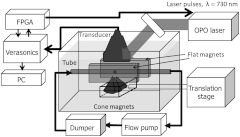
The experimental setup is shown in Fig. 1, which consist of a dual-magnet system, a flow recirculation system, an optical illumination system, and an US acquisition system.
Fig. 1.
Diagram of the experimental setup including a dual-magnet system, a recirculation system, a light delivery system, and an acoustic acquisition system.
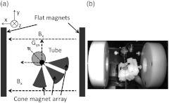
The dual magnet system, shown in Fig. 2 as a diagram and a photograph, was designed and built to produce an external magnetic field at the tube region to efficiently trap contrast agent targeted beads circulating in the flow stream and then manipulate them. The system consists of two parts designed for distinctively different tasks. One is to produce a homogeneous field () to magnetize the magnetic contrast agents, and the other with a high magnetic field gradient is to provide a strong magnetic trapping force to the magnetized contrast agents. Two disc Neodymium (NdFeB) magnets ( disc, Emovendo, WV) mounted in a Delrin holding system was fixed at opposite sides of the tube filled with the solution under study. The separation of 60 mm between the two magnets produced a 0.04 Tesla magnetizing field in the tube region.
Fig. 2.
(a) Diagram and (b) photograph of dual-magnet system.
A magnet array consisting of three cone magnets ( cones, Emovendo, WV) mounted in a Delrin holding system was used to generate a high magnetic field gradient(—derivative of vertical field with respect to lateral dimension—this is the primary gradient, with magnitude of about , contributing to a vertical force in the tube region at 1 mm distance) perpendicular to the flow direction to trap beads toward the lower wall of the tube, in which the flow rate was close to zero due to laminar phenomena. The cone magnet array was driven by a linear actuator motor (T-LA60A, Zaber, BC, Canada) to move it under computer control in the direction toward/away from the tube to apply/remove the strong magnetic force within 3 s. Also, a translation stage was used to move the cone magnet array along the tube to manipulate accumulated beads.
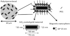
A PTFE (Teflon) tube (SLTT-16-72, Zeus, WA) with an inner diameter of 1.6 mm and a thickness of 38 μm mimicking a peripheral blood vessel was positioned in a tank filled with DI water. This tube was filled with a water-based solution of beads with targeted MNS-GNR contrast agents. Figure 3 shows a diagram of targeting the coupled contrast agent to the microscale beads. based MNSs (Ocean Nanotech) with an average diameter of 15 nm were complexed with GNRs ( in minor axis and in major axis) coated with a layer of 10 nm thickness. The GNRs were prepared using a seed-mediated growth method24 and stabilized with PEG. The resulting nanoprobes, with an absorption peak around a wavelength of 730 nm, were targeted to 10 μm diameter polystyrene beads (AP-100-10, Spherotech, IL) through EDC conjugation reaction. The nonattached nanoprobes suspended in the solution were washed out through centrifugation. The concentration of beads in a water solution was beads per milliliter, and the number of nanoprobes per bead targeted was approximately 100,000, as estimated by dividing the number of attached nanoprobes (i.e., total number of nanoparticles in original solution subtracted by the number that were washed out after conjugation with the beads) by the bead number. The sample solution was recirculated within the tube using a flow pumping motor (WU-77301-20, MasterFlex, IL) with a maximum rate of , which is nearly twice that in a human radial artery.25 The flow was further stabilized by placing a dumper prior to the measurement region to reduce pulsatility.
Fig. 3.
Diagram of targeting coupled MNS-GNR contrast agents to micro-scale polystyrene bead.
A wavelength tunable OPO system (Surelite OPO plus, Continuum, Santa Clara, CA) pumped by a frequency-doubled pulsed YAG laser (Surelite I-20, Continuum, Santa Clara, CA) delivered 5 ns pulses with a repetition rate of 20 Hz. The wavelength was tuned to 730 nm, corresponding to the peak absorption wavelength of the nanoprobe. The laser irradiated the tube from the top, tilted by an angle of about 45 deg to the vertical line, creating a 15 mm diameter spot with fluence of about , which was estimated from the measured total pulse energy and illumination area. The level was well below maximum permissible exposures26 and made it acceptable for clinical applications. A linear array transducer (AT8L12–5 50 mm, Broadsound, Taiwan) interfaced with an US imaging system (Verasonics, WA) was used for US pulse-echo imaging and PA signal detection. The transducer was positioned above the tube at a distance of 18 mm, and its lateral direction was aligned parallel to the tube so that objects moving along the tube could be monitored. Given an aperture length of 25.6 mm (128 elements), the reconstruction corresponded to a total detection angle of approximately 71 deg. A field-programmable gate array (FPGA) was used to synchronize the laser and Verasonics system to alternatively acquire one PA image and one US image, each at a frame rate of 4 Hz.
In the first part of the experiment, the bead trapping efficiency of the dual magnet system was demonstrated. The cone magnet array was initially placed 10 mm away from the tube to produce nearly zero magnetic force at the tube region. At a certain time, the cone magnet array was moved toward the tube until it was 1 mm from the tube surface. It stayed in this position for about 8 min to maintain a strong magnetic trapping force to the beads flowing in the stream. The trapping force was then removed by moving the cone magnet array away from the tube.
In the second part of the experiment, the cone magnet array was not removed at the last step. Instead, it was kept at a 1 mm distance from the tube and moved along the tube (both downstream and upstream) to see if accumulated beads could be manipulated in the flow (i.e., the movement of beads corresponding to the movement of the cone magnet array).
To more closely mimic in vivo trapping and manipulation of CTCs in blood flow, a small amount of ink was added to the initial water solution to form an ink solution with an absorption coefficient of at an optical wavelength of 730 nm, which can be considered as a good approximation to blood optical absorption in the near infrared range. Also, a small amount of milk was added into the water tank forming a reduced scattering coefficient of to mimic the optical scattering of tissues. Considering the 5 cm imaging depth (i.e., length of laser path from water surface to the tube region) in this study, this is equivalent to a reduced scattering coefficient of for 1 cm imaging depth, which is closer to the expected penetration depth in peripheral blood vessel imaging applications. The manipulation experiment was then repeated.
3. Results and Discussion
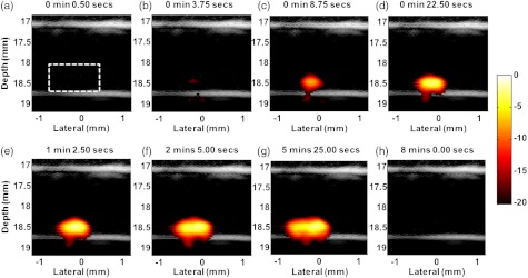
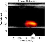
Figure 4 depicts US/PA fusion images showing the process of trapping MNS-GNR targeted polystyrene beads in a right-to-left stream with a flow rate of . US signals are displayed in gray scale, while PA signals are presented in “hot” pseudo-color. The US signals at the top and bottom boundaries of the PTFE tube are clearly seen. No PA sources were detected right after moving the cone magnets near the tube [Fig. 4(a), 0.5 s], indicating no beads stayed in the tube region at the beginning. The PA signals gradually increased and expanded with time due to the accumulation of beads trapped by the strong magnetic force [Fig. 4(b) to 4(g)]. The accumulated beads lengthened to grow a “tail” toward the left due to the drag force of the flow, especially in the image corresponding to the time moment of 5 min and 25 s [Fig. 4(g)]. At the time moment of 8 min [Fig. 4(h)], the trapped beads were released by removing the cone magnets and PA signals disappeared.
Fig. 4.
Fusion images () of beads targeted with composite particles and trapped in flow stream at different time points of magnet action. Dashed rectangle indicates the region used to calculate mean amplitude.
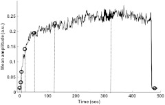
The accumulation curve is shown in Fig. 5, in which the mean PA signal amplitude within the tube region [dashed rectangular in Fig. 4(a)] was calculated as a function of time. The mean PA signal amplitude increases rapidly after applying the cone magnets at time , and gradually reaches a plateau at about 80 s, which means that the designed dual magnet system can efficiently trap the beads in a fast flow rate of . After removing the cone magnets at about 480 s, the mean amplitude returned to the background level, indicating that all trapped beads flowed away. Note that a relatively higher concentration of beads per milliliter solution () were imaged compared to a low concentration of CTCs in the blood (). Nevertheless, accumulation of the targeted beads due to the magnetic trapping force significantly increased the concentration of GNR in a local region, thus generating effective PA signal sources that can be detected.
Fig. 5.
Mean amplitude of the PA signal inside the tube in the region of particle accumulation. Positions of circles correspond to images represented in Fig. 4.
The sensitivity of detecting CTCs can be further improved by magnetically manipulating them to create movement coherent with the external magnetic field. By applying motion filters on the resultant images, unwanted background signals from sources not being targeted can be suppressed because they are static or move incoherently with the magnetic field. The process of manipulating trapped beads while moving the cone magnets was recorded sequentially and is presented in Video 1, in which the US signals of the top and bottom walls are in gray scale while the PA signals indicating the beads being trapped are in pseudo-color. The white triangle on the bottom indicates the position of the cone magnet array. The flow was from right to left at a rate of . The frame rate (frames per second) of the movie changes in different sections to illustrate different phases of manipulation.
Video 1.
Prior to the lateral movement of the cone magnets, they were kept static at a lateral position of 0.5 mm to accumulate flowing beads for 5 min (before 0:00). In the time period of 0:00 to 3:00, the movement of the cone magnets was controlled from the right to left (downstream), and the trapped beads followed fast and easily—the movie is played at 150 frames per second. From 3:00 to 5:00, both magnets and beads stayed at the left of the frame, and the frame rate is 300 frames per second. Next from 5:00 to 12:25, the cone magnets were moved to the right (upstream), then, to the left, until stopped in the middle. The movie is played at 150 frames per second. These segments show that it was harder for the beads to follow the movement of the magnets when moving upstream. The shape of the bead cluster became longer and was divided into two groups around 6:30 to 7:30. This is due to the downstream drag force of the flow. Near the end of the movie (from 12:25 to 12:40), the frame rate is quite slow (10 frames per second) to clearly illustrate release of the beads. Right after removing the cone magnets (i.e., disappearance of the white triangle), beads flowed away with the flow to the left because the magnetic trapping force was lost.
The undesirable stationary background or other PA sources insensitive to the magnet field can be suppressed by applying motion filters on received PA signals. Figure 6(a) and 6(b) shows two images of trapped beads in ink solution with the cone magnets at different positions (shown as the black triangles). The PA signals appeared at the lateral positions corresponding to the cone magnet array position. The strong PA signals on the top wall that did not appear in the water solution were induced by the added ink. For in vivo detection of CTCs in a blood vessel, background signals may overlap with PA signals of the trapped CTCs and make it difficult to distinguish targeted cells. Here, a simple form of motion filter, image subtraction, was adopted for mmPA imaging. The differential image of Fig. 6(a) and 6(b) is shown in Fig. 6(c), in which the ink signals are suppressed but the beads signals are preserved.
Fig. 6.
Fusion Images () of manipulating targeted beads in ink solution with flow stream. Images (a) and (b) acquired for two different positions of the cone magnet array. (c) Differential image of (a) and (b). Triangles indicate the magnet positions.
By comparing the contrast between ink signals along the top wall and the primary particle signals before [Fig. 6(a) and 6(b)] and after [Fig. 6(c)] image subtraction, the background suppression ratio was computed to be 15.1 dB. This ratio was limited primarily by a small residual signal that moved coherently with the magnets. Based on measurements with water-only solutions, the residue is dominated by weak PA signals arising from the cone magnets support structure that moved with the magnets. A more robust magnet design can greatly reduce this artifact. Also, laser energy fluctuations during image acquisition may lead to imperfect subtraction. For in vivo studies, complete elimination of the background is nearly impossible because the optical absorption distribution of the background will be easily affected in real blood by many factors, such as changes in blood oxygenation, blood cell concentration, and even motion due to breathing. Nevertheless, we believe that the background signal level can be significantly suppressed with mmPA imaging and thereby specific contrast can be significantly enhanced for the PA detection of CTCs.
4. Conclusions
In the current phantom study, the experimental results clearly demonstrate that the MNS-GNR targeted polystyrene beads mimicking CTCs in the vasculature can be magnetically trapped in a flow stream. The flow rate for successful trapping of the beads can reach at least , which is twice that of a human radial artery. Although constant, rather than pulsatile, flow was used, these results demonstrate the potential of the dual magnet trapping principle for clinical use in identifying CTCs. It is shown that in the presence of a large PA background (i.e., optical absorptive ink solution mimicking blood), the contrast of the desired PA signal induced by beads can be significantly enhanced using mmPA imaging. The differential image corresponding to the difference of PA images reconstructed for two separate positions of accumulated beads reduces the background level by more than 15 dB. Before moving toward preclinical studies with a specially designed magnetic delivery system appropriate for trapping and manipulation of CTCs in small animal vessels, we plan to continue in vitro studies using real metastatic cells targeted by composite contrast agents through specific biological conjugation (e.g., antibody-antigen binding).27 Trapping and manipulation experiments will be performed in a more realistic blood flow environment to better demonstrate the potential clinical applicability of mmPA imaging for background suppression in PA detection of CTCs.
The detection sensitivity, defined as the minimum detectable number of beads (MDB), is roughly estimated as:
where is the background signal level measured in the region where beads are trapped before the magnetic force is applied, is the integrated signal of accumulated beads, and is the total bead number. The signal amplitude is assumed to be linearly proportional to the number of beads. With a total of (), the MDB was estimated at about 50 beads (17 beads per ml) at a flow rate. This number overestimates the MDB because not all beads flowing in the stream were trapped, so that a smaller should be used in the equation. Optical screening should also be considered, since the linearity assumption is violated at high bead concentrations, especially as many beads accumulate together. For in vivo studies, the sensitivity can be further improved because the number of particles per cell can increase due to potential endocytosis of targeted contrast agents. Also, the laser fluence can be increased as long as it is below maximum permissible exposures. In summary, the current system has the potential to detect a very small number of CTCs per ml, and future sensitivity improvements are expected with a better designed ultrasonic acquisition system. Future studies will focus on improving the current system to achieve the ultimate sensitivity of detecting single targeted CTCs trafficking in the peripheral circulation.
Acknowledgments
We acknowledge support of this study by NIH (R01CA131797, R01CA140295, and T32 CA138312), NSF 0645080, the Life Sciences Discovery Fund 3292512, and the Department of Bioengineering at the University of Washington.
References
- 1.Weigelt B., Peterse J. L., van’t Veer L. J., “Breast cancer metastasis: markers and models,” Nat. Rev. Cancer 5(8), 591–602 (2005).http://dx.doi.org/10.1038/nrc1670 [DOI] [PubMed] [Google Scholar]
- 2.De Giorgi V., et al. , “Application of a filtration- and isolation-by-size technique for the detection of circulating tumor cells in cutaneous melanoma,” J. Invest. Dermatol. 130(10), 2440–2447 (2010).http://dx.doi.org/10.1038/jid.2010.141 [DOI] [PubMed] [Google Scholar]
- 3.Tuchin V. V., T´arnok A., Zharov V. P., “In vivo flow cytometry: ahorizon of opportunities,” Cytom. Part A. 79A(10), 737–745 (2011).http://dx.doi.org/10.1002/cyto.a.v79a.10 [DOI] [PMC free article] [PubMed] [Google Scholar]
- 4.Miller M. C., Doyle G. V., Terstappen L. W. M. M., “Significance of circulating tumor cells detected by the cell search system in patients with metastatic breast colorectal and prostate cancer,” J. Oncol. 2010, 617421 (2010).http://dx.doi.10.1155/2010/617421 [DOI] [PMC free article] [PubMed] [Google Scholar]
- 5.Fleisher M., “A new opportunity for therapeutic management of cancer patients,” Clin. Lab. News. 34(11) (2008). [Google Scholar]
- 6.Nagrath S. L. V., et al. , “Isolation of rare circulating tumour cells in cancer patients by microchip technology,” Nature 450(7173), 1235–1239 (2007).http://dx.doi.org/10.1038/nature06385 [DOI] [PMC free article] [PubMed] [Google Scholar]
- 7.Zhenga S. H., et al. , “Membrane microfilter device for selective capture, electrolysis and genomic analysis of human circulating tumor cells,” J. Chromatogr. 1162(2), 154–161 (2007).http://dx.doi.org/10.1016/j.chroma.2007.05.064 [DOI] [PubMed] [Google Scholar]
- 8.Shaffer D. R., et al. , “Circulating tumor cell analysis in patients with progressive castration-resistant prostate cancer,” Clin. Cancer Res. 13(7), 2023–2029 (2007).http://dx.doi.org/10.1158/1078-0432.CCR-06-2701 [DOI] [PubMed] [Google Scholar]
- 9.Wang L. V., Photoacoustic Imaging and Spectroscopy, CRC, BocaRaton, FL: (2009). [Google Scholar]
- 10.Ermilov S. A., et al. , “Laser optoacoustic imaging system for detectionof breast cancer,” J Biomed. Opt. 14(2), 024007 (2009).http://dx.doi.org/10.1117/1.3086616 [DOI] [PubMed] [Google Scholar]
- 11.Li H., Wang L. V., “Photoacoustic tomography and sensing in biomedicine.” Phys. Med. Biol. 54(19), R59–R97 (2009).http://dx.doi.org/10.1088/0031-9155/54/19/R01 [DOI] [PMC free article] [PubMed] [Google Scholar]
- 12.Emelianov S. Y., Li P. C., Donnell M. O’. “Photoacoustics for molecular imaging and therapy.” Phys. Today 62(5), 3439 (2009).http://dx.doi.org/10.1063/1.3141939 [DOI] [PMC free article] [PubMed] [Google Scholar]
- 13.Li P. C., et al. , “In vivo photoacoustic molecular imaging with simultaneous multiple selective targeting using antibody-conjugated gold nanorods.” Opt. Express 16(23), 18605–18615 (2008).http://dx.doi.org/10.1364/OE.16.018605 [DOI] [PubMed] [Google Scholar]
- 14.Huang S. W., et al. , “Differential-absorption photoacoustic imaging for contrast enhancement,” Opt. Lett. 34(16), 2393–2395 (2009).http://dx.doi.org/10.1364/OL.34.002393 [DOI] [PubMed] [Google Scholar]
- 15.Hu S., Maslov K., Tsytsarev V., Wang L. V., “Functional transcranial brain imaging by optical-resolution photoacoustic microscopy,” J. Biomed. Opt. 14(4), 040503 (2009).http://dx.doi.org/10.1117/1.3194136 [DOI] [PMC free article] [PubMed] [Google Scholar]
- 16.Razansky D., Buehler A., Ntziachristos V., “Volumetric real-time multispectral optoacoustic tomography of biomarkers,” Nat. Protocols 6(8), 1121–1129 (2011).http://dx.doi.org/10.1038/nprot.2011.351 [DOI] [PubMed] [Google Scholar]
- 17.Galanzha E. I., et al. , “In vivo magnetic enrichment and multiplex photoacoustic detection of circulating tumour cells,” Nat. Nanotech. 4(12), 855–860 (2009).http://dx.doi.org/10.1038/nnano.2009.333 [DOI] [PMC free article] [PubMed] [Google Scholar]
- 18.Jin Y., et al. , “Multifunctional nanoparticles as coupled contrast agents,” Nat. Commun. 1(41) (2010).http://dx.doi.org/10.1038/ncomms1042 [DOI] [PMC free article] [PubMed] [Google Scholar]
- 19.Jia C., et al. , “Contrast-enhanced photoacoustic imaging.” in Proc. 2010 IEEE Ultrasonics Symposium, IEEE Ultrasonics, Ferroelectrics, and Frequency Control Society, San Diego: (2010). [Google Scholar]
- 20.Jia C., et al. , “Dynamic manipulation of magnetic contrast agents in photoacoustic imaging.” Proc. SPIE 7899, 78991R (2011).http://dx.doi.org/10.1117/12.876057 [Google Scholar]
- 21.Xia J., et al. , “Suppression of background signal inmagnetomotive photoacoustic imaging of magnetic microspheres mimicking targeted cells,” J. Biomed. Opt. 17(6), 061224 (2012).http://dx.doi.org/10.1117/1.JBO.17.6.061224 [DOI] [PMC free article] [PubMed] [Google Scholar]
- 22.Qu M., et al. “Magneto-photo-acoustic imaging,” Biomed. Opt. Express 2(2), 385–395 (2011).http://dx.doi.org/10.1364/BOE.2.000385 [DOI] [PMC free article] [PubMed] [Google Scholar]
- 23.Qu M., et al. , “Magneto photo acoustic imaging using dual contrast agent,” in Proc. 2010 IEEE Ultrasonics Symposium, San Diego: (2010). [Google Scholar]
- 24.Nikoobakht B., El-Sayed M. A., “Preparation and growth mechanism of gold nanorods (NRs) using seed-mediated growthmethod,” Chem. Mater. 15(10), 1957–1962 (2003).http://dx.doi.org/10.1021/cm020732l [Google Scholar]
- 25.Moore D. F., et al. , “Arterial wall properties and womersley flow in fabry disease,” BMC Cardiovasc. Disord. 2(1) (2002).http://dx.doi.org/10.1186/1471-2261-2-1 [DOI] [PMC free article] [PubMed] [Google Scholar]
- 26.American National Standard for the Safe Use of Lasers in Health Care Facilities: Standard Z136.1-2000,” A. N. S. Institute. Ed. ANSI, Inc. New York, NY: (2000). [Google Scholar]
- 27.Wang C., et al. , “Gold nanoparticle “nano-pearl-necklaces” for simultaneous targeting, dual-mode imaging, and photothermal ablation of cancer cells,” Angew. Chem. Int. Ed. 48(15), 2759–2763 (2009).http://dx.doi.org/10.1002/anie.v48:15 [DOI] [PubMed] [Google Scholar]
Associated Data
This section collects any data citations, data availability statements, or supplementary materials included in this article.


