Abstract
Several fields have created ontologies for their subdomains. For example, the biological sciences have developed extensive ontologies such as the Gene Ontology, which is considered a great success. Ontologies could provide similar advantages to the Modeling and Simulation community. They provide a way to establish common vocabularies and capture knowledge about a particular domain with community-wide agreement. Ontologies can support significantly improved (semantic) search and browsing, integration of heterogeneous information sources, and improved knowledge discovery capabilities. This paper discusses the design and development of an ontology for Modeling and Simulation called the Discrete-event Modeling Ontology (DeMO), and it presents prototype applications that demonstrate various uses and benefits that such an ontology may provide to the Modeling and Simulation community.
Keywords: Discrete systems, simulation environments, standards, Web-based environments
1. Introduction
Most software designs reflect a commitment to a particular view of reality that shapes and directs their implementation by developers. In the early 1960s, Lackner1 recognized that Discrete-event Simulation (DES) software conformed to this pattern when he noted that programming languages developed for the purpose of creating DES systems tended to support specific views of reality. A few years later, Kiviat's2 discussion of simulation programming languages (SPLs) led to a basic taxonomy for DES that includes the three classical world views: event scheduling (ES), activity scanning (AS), and process interaction (PI). The concepts associated with a particular world view were designed into a SPL and were implicitly adopted by the simulations developed using the language. In the years since Kiviat's discussion of the classical world views, several taxonomies, formalisms, and modeling techniques for Modeling and Simulation (M&S) have been developed.
Unfortunately, the field of M&S suffers the same problem as other disciplines of computing in that taxonomies exist on paper, but there is no efficient way to connect what one group is doing in one area to another group in a different area, for example, groups doing Petri Nets (PNs)3 and Event Graphs (EGs)4 are not efficiently connected. If machine-readable links between the concepts used by various formalisms existed, they could be used in databases, query engines, and human–computer interaction models. In addition, the organization of such knowledge would help increase interoperability, integration, and reuse of simulation artifacts. Emerging Semantic Web technologies provide an avenue for organizing M&S knowledge as described above.
The M&S community has benefited through the use of current Web technologies, and emerging Web technologies have the potential to provide even greater benefit. Web-based simulation5–8 was an early example of Web technology use for M&S. It began with the idea that the Web could have a profound impact on how users interact with simulation. Much of this initial work focused on providing an infrastructure to support Web-based simulation. In more recent years, the emergence of the Extensible Markup Language (XML) began to shift the focus of researchers toward the development of simulations using XML-based applications and schemas.9–11 XML is designed to facilitate document exchange and can make use of a schema language, such as XML Schema, to provide a structure and some level of standardization of semantics for a group of related documents. It enables Web documents to carry more meaningful tags than are available in Hypertext Markup Language (HTML), and it allows the documents to carry some semantics. Unfortunately, XML alone cannot provide semantics that are rich enough to achieve many of the M&S community's goals, that is, model discovery, interoperability, integration, and reuse.
The next generation of the Web, known as the Semantic Web,12 promises to provide machine-readable and meaningful descriptions of Web resources in order to improve discovery, integration, and use/reuse of such resources. The M&S community may reap significant benefits through the use of Semantic Web technology.13 One of the most important contributions of the Semantic Web for M&S is the creation of ontologies for specific domains. According to Gruber,14 ontologies are structured descriptions that categorize concepts and relationships among concepts within a particular knowledge domain. Ontologies are, like taxonomies, used to classify entities within a domain, but they hold several advantages over traditional taxonomies in that they allow the entities to have properties and relationships. They also allow types of things within a particular domain to be defined as classes, and the meaning of a class is captured via its position within subclass-of/is-a hierarchy as well as by its properties, relationships, and restrictions. Because ontologies are meant to define a domain and to be shared by many, the most useful ontologies are created by expert groups. The use of ontologies in M&S has recently emerged as a growing area of research interest as evidenced by the creation of the Discrete-event Modeling Ontology (DeMO),15 the evaluation of the Command and Control Information Exchange Data Model (C2IEDM) as an interoperability enabling ontology,16 the development of the Process Interaction Modeling Ontology for Discrete-event Simulations (PIMODES),17 the development of the Component Simulation and Modeling Ontology (COSMO),18 the use of domain ontologies in agent-supported interoperability of simulations,19 and the use of the Discrete-event Systems Specification (DEVS) formalism20 as an ontology for M&S.21 At this point it may be useful to review some of these recent efforts to use ontologies in the support of M&S.
Lacy and Gerber22 proposed that ontologies developed using the Web Ontology Language (OWL)23 be used as data interchange formats (DIFs) to support simulation interoperability. They called attention to the fact that XML is often used as a DIF but that it is somewhat deficient. The parties involved in the data interchange must have an understanding of the meaning of the data contained in the DIF, and since XML does not contain explicit semantics, developers who understand the meaning of the data in the XML document are required to program the simulations, which exchange data via the DIF to conform to the implicit meaning of the data. Lacy later followed through with his suggestion to use OWL ontologies as DIFs by developing the PIMODES ontology, which serves as an implementation independent DIF for DES models that are described using the PI world view. PI simulation models developed using particular simulation software packages may be transformed to, or from, PIMODES instance data files in order to exchange the models with other simulation software packages.
Tolk and Muguria24 discuss the idea that in order to achieve meaningful interoperability among M&S applications, interoperability of conceptual models must be considered, and they introduce the Levels of Conceptual Interoperability Model (LCIM). The LCIM describes various levels of conceptual interoper-ability where the level of conceptual understanding between interoperating systems increases as the level of conceptual interoperability in the LCIM increases. The model has undergone gradual enhancements25,26 since its inception, and the current version contains seven levels ranging from level 0, where systems have no interoperability, to level 6, where a complete understanding of the concepts used by target and source conceptual models is sharable between the models. Level 3, ‘The Semantic Level’, specifies that the meaning of exchanged data is shared between systems by means of common reference models. This level introduces the need for the type hierarchies for the various interconnected systems to communicate via conformance or mediation. Level 4, ‘The Pragmatic Level’, takes the concept of typing further by specifying that the context as well as the meaning of the exchanged data is shared between systems. This requires that the common reference models used by the systems have ontologies that are able to supply sufficient ontological information about the data being exchanged. Tolk16 later proposes a method for evaluating an ontology for completeness, and he applies the method to the C2IEDM to evaluate its fitness to serve as an interoperability enabling ontology for military command and control systems. The proposed method benefits the M&S community in that it is useful for evaluating data models to assess their fitness as interoperability enabling ontologies.
Yilmaz and Paspuleti19 propose a meta-level framework in which agents are used to coordinate the exchange of data and services among simulations. The agents within the framework are intended to facilitate agent-mediated interoperation of simulations. Their strategy proposes four types of agents: (1) a facilitator agent acts as a controller and delegates requests to other agents that perform specific tasks associated with simulation interoperation; (2) a mediation agent uses a common reference model to convert data exchanged between simulations that use different encoding standards; (3) brokering between producer and consumer simulations is achieved via a broker agent, which uses various brokering protocols that are able to take the constraints of specific simulations into account; and (4) a matchmaker agent uses measures of conceptual distance between concepts (Concept-level Matchmaking), the effort needed to align the properties of concepts (Attribute-based Matchmaking), and the structural similarity between concepts (Concept-based Matchmaking) in order to allow providers and requesters to exchange information and services. Concept-level matchmaking is of particular interest in the study of how ontologies are being used to support M&S, since it uses domain ontologies to measure the distance between the concepts requested by a simulation and the concepts available via the framework.
COSMO18 describes simulation components and compositions. It was developed to work in conjunction with the Composable Discrete-event Simulation System (CODES), which is a hierarchical component framework intended to support component-based M&S. The components used by CODES are given semantically enriched descriptions using COSMO ontology classes. These descriptions are used by CODES when performing component discovery and in determining whether components are semantically compatible with one another. According to Teo and Szabo,18 ‘two components are semantically compatible if the data exchanged between them is correct and meaningful and their behaviors are aligned’.
Zeigler et al.20 present a conceptual framework that may serve as a foundation ontology for development in the M&S domain. In this framework entities and relationships among them are described using systems theory. The computational implementation of the framework is known as DEVS and it can be used for modeling discrete-event systems. Zeigler and Hammonds27 introduce a methodology that makes use of DEVS and the System Entity Structure (SES) to perform what they refer to as M&S-based Data Engineering. The methodology generates ontologies that will be referenced by producers and consumers of information for purposes of exchanging meaningful information. The ontologies generated via this methodology go beyond the Semantic Level of the LCIM by introducing pragmatics, but they do not claim to reach the Conceptual Interoperability Level. Systems which reference an ontology that contains pragmatics gain access to not only the meaning of information, but also how it is intended to be used.
Miller et al.15 propose the creation of a general DES ontology (DeMO), which represents the domain of discrete-event modeling. DeMO describes the classic DES world views as well as a variety of DES formalisms and modeling techniques that conform to the world views. It has also been used by Silver et al.28,29 to support the Ontology-driven Simulation (ODS)30 of PI and PN models. DeMO style of ODS allows conceptual models represented as instances of domain ontology classes to be transformed into instances of DeMO classes that represent the same concepts using a particular DES formalism. A category-specific code generator may then be used to transform a conceptual model represented using DeMO class instances into an executable simulation model.
In this paper, we look at the development of DeMO and propose several additional ways that it may be used to benefit the discipline of M&S. The remainder of this paper is structured as follows. In Section 2, we consider languages for defining ontologies suitable for the Semantic Web. Section 3 takes a brief look at existing taxonomies for M&S and DES frameworks, discusses the basic taxonomy upon which DeMO is built, and then describes the structure of the ontology. Applications and benefits of DeMO are discussed in Section 4, and the paper is wrapped up with conclusions and future work in Section 5.
2. Ontologies for the Semantic Web
Although ontology languages, such as the Knowledge Interchange Format, were developed in the 1990s, the Semantic Web initiative has reinvigorated efforts to create a new ontology language that has wider appeal. The Knowledge Interchange Format has the expressive power of First Order Logic (FOL), which enables complex concepts to be precisely described. The truth value of any FOL expression can be effectively proved (FOL is sound), but it is not possible to generate all true statements (FOL is incomplete), thus FOL is said to be semi-decidable.31,32 For the Semantic Web, some researchers feel that a decidable language would be more appropriate, since limiting the language expressivity will improve its computability/tractability. OWL was designed with this expressivity/complexity trade-off in mind. In order to facilitate this trade-off, it comes in three flavors: OWL Lite, OWL DL (Description Logic), and OWL Full, with the first two being decidable. Work is also underway on the next generation of OWL, OWL 2.33 OWL 2 will update the capabilities of OWL to enhance its expressive power, extend its support of datatypes and annotations, provide metamodeling capabilities, and allow the use of database style keys. OWL 2 will also introduce three new language profiles, OWL 2 EL (EL refers to the EL family of description logics, which is limited to existential quantification and intersection of concepts), OWL 2 QL (Query Language), and OWL 2 RL (Rule Language), intended to ease the task of ontology implementation. Each of the profiles imposes limits upon OWL 2, allowing it to best support specific types of ontologies. OWL 2 EL is based on the lightweight description logic EL++,34 and it is best suited for ontologies that contain large numbers of classes and/or properties, while OWL 2 QL allows queries to be written in a standard relational query language and is intended to support ontologies that contain large amounts of data. OWL 2 RL can implement reasoning using a standard rule language and is well suited for ontologies that will require reasoning to be performed efficiently.
2.1. Structure of the Semantic Web
Before going into more detail about ontologies, we will give a brief overview of the architecture of the emerging Semantic Web. This will provide a better perspective on the work presented in this paper. At the XML 2000 Conference, Berners-Lee35 presented his plan for the Semantic Web Architecture. The architecture consists of five layers, the first of which is the resource/data layer. The XML language exists in this layer, and it forms the basic syntax for documenting structured information on the Semantic Web. The next layer, the meta-data layer, contains the Resource Description Framework (RDF) and RDF Schema languages, which allow semantics with machine-predictable tags to be added to the data model. The ontology layer houses the OWL language. OWL is more expressive than RDF in that it can easily express class relationships and property constraints. This layer serves as the basis for later logical inference. Above the ontology layer we find the rule/logic layer where rule languages, such as the Semantic Web Rule Language (SWRL) and the Rule Interchange Format (RIF), may use information from the ontology layer to make deductions about the facts and relations not explicitly stated in the ontology. The last layer in the architecture, the proof/trust layer, is intended to allow automatic agents to send and accept proofs necessary for interchange. The idea is that with proofs, trust can be built up among a community of Web users.12 As can be seen in Table 1, each layer of the Semantic Web has an associated Web language. In the sections below, we will look at the ontology and rule/logic layers of the architecture, since they are directly related to our topic.
Table 1.
Layers of the Semantic Web architecture
| Layer | Principal Language | Name (URL) |
|---|---|---|
| Proof/trust | Future work | |
| Rule/logic | RIF, SWRL | Extensible Markup Language, XML Schema Definition (www.w3.org/XML, www.w3.org/XML/Schema) |
| Ontology | OWL (Lite, DL, Full) OWL 2 (EL, QL, RL) |
Web Ontology Language (www.w3.org/2004/OWL/) |
| OWL 2 Web Ontology Language (http://www.w3.org/TR/owl2-profiles) | ||
| Meta-data | RDF, RDF Schema | RULE Interchange Format (http://www.w3.org/TR/rif-core) |
| Semantic Web Rule Language (www.w3.org/Submission/SWRL/) | ||
| Resource/data | XML, XSD | Resource Description Framework, RDF Schema (www.w3.org/RDF) |
2.2. Ontology Layer – Web Ontology Language
OWL has been approved by the World Wide Web Consortium (W3C) to be the standard language for expressing Web-accessible ontologies. It incorporates features from and extends upon RDF and RDF Schema. Compared to RDF Schema, OWL has more features for describing properties and classes. It allows relations between classes (e.g. disjointness), richer typing of properties, cardinality of properties, and characteristics of properties (e.g. symmetry, transitivity).
OWL has three variants: OWL Lite, which has expressiveness similar to RDF Schema, OWL DL, based on description logics that are computationally complete and decidable, and OWL Full, which provides additional features but sacrifices decidability.
Our ontology is represented in OWL DL and was developed using Protégé 4.0 (protege.stanford.edu). Protégé is one of the most popular ontology editing tools currently available (see Denny36 for a survey). OWL DL allows the definition of a class to represent specific concepts. Classes may: (1) be divided into subclasses; (2) have properties/relationships; and (3) have instances. Properties/relationships may have certain characteristics (e.g. transitive, symmetric, functional, inverse, cardinality) and are divided into basic types: object properties and data properties. As such, OWL shares much in common with Entity-relationship Modeling and the Unified Modeling Language (UML). Entity-relationship Modeling is intended for data modeling, UML is intended for software modeling, and OWL is intended for ontology modeling and knowledge representation consistent with the Web infrastructure (for a comparison of UML and OWL see Evermann37). Ontologies developed using OWL can be used to automatically classify individuals (class instances) based on the knowledge resident in an ontology, therefore OWL must provide a way to describe the conditions necessary for membership in a class. OWL does this by allowing qualifiers to be placed on property-class relationships, which specify necessary and sufficient conditions.
2.3. Rule/Logic Layer –Semantic Web Rule Language
There are proposals for languages at the Rule/Logic Layer, including SWRL, which go beyond OWL DL by providing the ability to write rules using a subset of Rule Markup Language (RuleML). In Protégé, SWRL may be used to create logic rules to be added to OWL descriptions. This enables more complex predicates to be created and used for more precise definitions of concepts and relationships that are otherwise beyond OWL's ability to represent. In addition, SWRL has built-ins for basic arithmetic (e.g. x + y) and comparisons (e.g. x < y). The rule/logic layer is in its preliminary stages of development, and while SWRL is currently the dominate rule language used in conjunction with OWL ontologies, the WC3 effort to standardize RIF38,39 is well under way. RIF provides a collection of rule-based languages to which other rule-based languages can be mapped in order to allow systems that use the different languages to share rule sets and other information with one another. Our use of SWRL to support ODS is discussed in Section 4.2, and we plan to make more extensive use of the languages associated with Rule/Logic layer in future work with DeMO.
3. Taxonomies for Discrete-event Modeling and DeMO
Models can be classified based on various characteristics: static versus dynamic, time varying versus time-invariant, continuous state versus discrete-state, time-driven versus event-driven, descriptive versus prescriptive, and analytic versus numeric.40,41 Surveying existing taxonomies is a useful way to begin the development of an ontology, hence we first give a brief review of existing simulation modeling taxonomies and then show how the existing discrete-event modeling formalisms are represented in DeMO.
3.1. Review of Existing Taxonomies
Given a system evolving over time, a model of it can be viewed simply as an approximation that captures or mimics the essential features of the system. Commonly, models are classified according to how they deal with time (static versus dynamic), state (discrete versus continuous), and randomness (deterministic versus stochastic).
There are two broad types of simulation modeling: continuous simulation and DES. The distinction is based on whether the state can change continuously (water level in a reservoir) or at discrete points in time (number of customers in a bank). Continuous changes are often modeled as differential equations in which both state and time are continuous. DES models are very popular for modeling many types of real-world systems, such as banks, hospitals, transportation systems, and computer networks. This paper will focuses on discrete-event models.
Within discrete-event modeling there are multiple ways to construct taxonomies. The development/use of SPLs led to the creation of taxonomies for DES. These languages allowed developers to define models using categories identified with a particular view of reality. Developers used the views implicit with the SPLs when contemplating a system.1 Kiviat's2 discussion of SPLs led to the basic taxonomy for DES, which includes the three world views: ES, AS, and PI. This type of taxonomy, in a more general context, which includes simulation, database, and workflow modeling, was discussed by Miller et al.42 and a portion of it is discussed below. Most of the diagrammatic simulation modeling techniques implicitly or explicitly depict entities (e.g. bank customers) flowing through a system. The classification/taxonomy below mentions several popular general simulation modeling techniques partitioned according to their principal world view.
- ES – These models focus on the events that occur in a system. When an event occurs, it instantaneously transforms the state of the system and/or schedules future events. Future events are scheduled by giving them a time-stamp and then placing them in a future-event list. Simulation time is advanced by setting the current time to the time-stamp of the earliest event (imminent event) on the list and processing that event.
- Simulation Event Graph (SEG) – In a SEG, nodes represent events that cause changes in the system state, while directed edges represent relationships between events.4 An edge may represent either a scheduling or a canceling relationship between events. Edges may also have associated conditions, under which future events will be scheduled (or canceled) and time delays, after which events will be scheduled (or canceled).
- AS – These models focus on activities and their preconditions (triggers). An activity consists of an event-pair (a start event and an end event). Activities are scheduled when their preconditions become true. The three-phase (TP) approach may be considered to be a more efficient variant of AS or a hybrid of AS and ES. Efficiency is gained by putting unconditional events on a future-event list as in ES and still triggering conditional events as in AS.
- Activity Cycle Diagrams (ACDs) – ACDs are graphs with two types of nodes (bipartite graphs), activities and queues (or wait states), where directed arcs connect either activities to queues or queues to activities.43,44 These diagrams depict the lifecycles of interacting entities flowing through a system.
- PNs – PNs are graphs with two types of nodes (bipartite graphs), transitions and places, where the arcs connect either transitions to places or places to transitions.3,45 A place is a storage area for tokens (entities), while a transition takes input token(s) to produce output token(s). A transition will fire if there is a (or are enough) token(s) at each of its input places. In Timed PNs, transitions have delays associated with them. Continuous PNs allow tokens to be represented as real values and transitions to fire continuously at a specified rate, and Hybrid PNs allow some parts of the PN graph to be discrete, as with traditional PNs, and other parts to be continuous, as with continuous PNs. Colored PNs allow tokens to have attributes.
- PI – These models focus on processes and their interaction with resources. A process captures the behavior of an entity as it flows through the system step by step.
- Activity Diagrams (ADs) – ADs are graphs consisting of a well-defined set of functional nodes such as start, terminate, delay, engage resource, and release resource.46 The graph shows the flow of entities as well as resources through the system.
- Network Diagrams (NDs) – Network(orblock)diagrams are used by many popular commercial simulation packages (e.g. General Purpose Simulation System (GPSS),47 Simulation Language for Alternative Modeling (SLAM),48 and SIMulation ANalysis (SIMAN)49). These NDs are similar to ADs but have more types of nodes corresponding to the underlying primitives supported in their associated simulation languages.
Besides these three classical world views, there are other popular approaches: (1) State-transition Models (e.g. Markov models); (2) DEVS models;20,40 and (3) Agent-based Simulation and Modeling.50–52
Agent-based modeling offers the simulation designer a different view of the objects being simulated. In particular, in the agent-based view, agents accept information (‘sense’), process that information (or ‘think’), and then affect the world in some way (‘act’). This is often referred to as the sense/think/act cycle. Even though this provides a new view for the simulation designer, it does not necessitate a new simulation paradigm.
Most agent-based simulation systems implement the agent-based view to the user, but ‘under the hood’ use a discrete-event-based simulation engine. Examples of this approach include SASSY52 and SPADES.53
Most of the simulation taxonomies are based on execution characteristics of models – scheduling events, scanning for activities, interacting processes. Fishwick54,55 suggests a different approach based on model syntax. In particular, he creates a taxonomy that conforms closely to the taxonomy of programming languages: declarative, functional, and constraint. By closely coupling simulation models with programming paradigms, this taxonomic exposition highlights the connections between models and programs. For example, declarative finite-state automata and PNs bear similar features to declarative programming languages based on rules and logic. Functional methods of simulation modeling are related to functional languages formalized with lambda calculus, such as Lisp. In this context we also mention Object-orientated Simulation (OOS, e.g. Simula).56 OOS does not represent a different user view of the simulated processes, but instead offers a principled approach to programming simulations. All of the major simulation paradigms can be implemented in an object-oriented manner. An example of how OOS can refine a traditional paradigm is given by Cota and Sargent.57
3.2. Alternative Ways of Categorizing Discrete-event Models
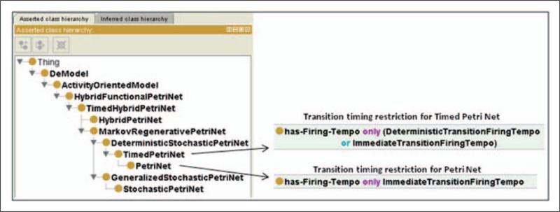
Another useful way to build a taxonomy is based on subsumption relationships between formalisms (e.g. Hybrid Functional Petri Nets (HFPNs) subsume Timed Hybrid Petri Nets (THPNs), which subsume Hybrid Petri Nets (HPNs)). This is the basic approach used to develop a taxonomy for DeMO, where a super-class representing a more general modeling technique will have less restrictions placed upon its properties than will a subclass that represents a more specific formalism. Figure 1 shows an example using the PN formalisms of DeMO's ActivityOrientedModel class. Notice that the TimedPetriNet class subsumes the PetriNet class. The reason for this is that Timed PNs allow both timed and immediate transitions, while traditional PNs allow only immediate transitions; therefore, DeMO's PetriNet class has an additional restriction placed on its has-Firing-Tempo property, which specifies that only immediate transitions are allowed.
Figure 1.
PN formalism class structure.
DES models have been categorized in various ways using a number of different taxonomies and classification schemes. They have been defined as abstract, dynamic, descriptive, numerical models.41 Cassandras and Lafortune58 define discrete-event systems as discrete-state, event-driven, time-invariant, dynamic models. Within the class of discrete-event models, further subclassification maybeachievedbymeansofthefollowing characteristics: stable versus unstable models, steady-state versus transient models, deterministic versus stochastic, and autonomous (no input) versus non-autonomous models.41 Nance59 divides simulation models into three main classes: Monte Carlo, continuous, and discrete-event. The International Council on Systems Engineering maintains and updates a broad taxonomy for software tools, including simulation tools.60 Schruben and Roeder61 propose a new way of organizing the highest levels of a modeling taxonomy for DES based on a dichotomy between resident entity cycle modeling and transient entity flow modeling as opposed to the three classical worldviews. An ontology can not only be used to classify and organize DES concepts in ways analogous to those used by existing taxonomies, but it can also encode the relationships that exist among concepts and capture instance data associated with concepts, thus an ontology is more than a taxonomy, and indeed may implicitly capture multiple taxonomies.
In the next section, we will show and discuss details of DeMO, which is, as the name implies, an ontology for the discrete-event modeling domain. In their essence, the models in the ontology capture how state evolves over time, although they may do so by focusing on other concepts, such as entity, event, or place. The number of state changes (via events) in the models represented by DeMO will be discrete, while time may be continuous, and state space may be either discrete or continuous. DeMO considers stochastic, deterministic, and hybrid (which are primarily discrete but may have continuous components) models.
The ontology currently focuses on the classical simulation world views and state-oriented models. Other modeling paradigms, such as object-oriented and agent-based, which are more focused on large-scale model development and include issues of hierarchical modeling and model reuse, are not included in the current version of DeMO.
3.3. DeMO
Assumptions about the meaning of concepts (semantics) used by particular SPLs and simulation software packages are designed into these tools and into the simulations that they produce. Because these assumptions are encoded into the software, they cannot be explicitly shared with other systems or humans who may wish to interconnect with them. DeMO attempts to overcome this limitation by explicitly describing the concepts and the relationships among the concepts assumed in each of the DES world views, using a language that can be understood by humans and processed by machines.
In this section, we put the pieces of the discrete-event modeling knowledge domain together and indicate how they are mapped to the constructs provided by OWL in order to create DeMO. DeMO was not created to support any particular application but was intended to be a generally useful ontology for the discrete-event modeling domain. Our goal was to capture as much machine-processable knowledge about the domain as was possible given our time and resource constraints.
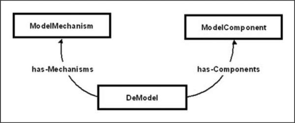
As mentioned earlier, in OWL DL (which is based on description logic) concepts are defined as classes, which may have sets of properties and relationships with other classes. New classes can be defined using inheritance, enumerations of instances, restrictions on properties, and logical statements. We begin our discussion of DeMO by observing that all discrete-event models should have some basic components from which they are built, as well as some rules (mechanisms) providing specifics of how the models should run. This is illustrated schematically in Figure 2.
Figure 2.
Schematic representation of the rationale behind DeMO design. All subclasses of DeModel are built from ModelComponents and put in motion by ModelMechanisms.
To capture this rationale in the ontology, the top-level abstract classes DeModel, ModelComponent, and ModelMechanism are created. Subclasses of DeModel correspond to modeling techniques for existing discrete-event modeling formalisms, such as Markov Chains, Queuing Networks, PNs, etc. Subclasses of ModelComponent define the building blocks of the model, which roughly correspond to the elements of the n-tuples used in formal definitions of models, and subclasses of class ModelMechanism define how the components operate within the model. Given this basic structure, one is required to take the following steps when defining a subclass of DeModel: (1) define the appropriate ModelComponent subclasses and relate them (via OWL properties) to this subclass of DeModel; (2) define the appropriate subclasses of ModelMechanism to explain how these components work; and (3) relate the ModelMechanism subclasses to the ModelComponent subclasses. Several of the concepts represented as subclasses of ModelComponent and ModelMechanism (such as state, event, time, etc.) are fundamental concepts in simulation and modeling.
3.3.1. The Structure of DeMO
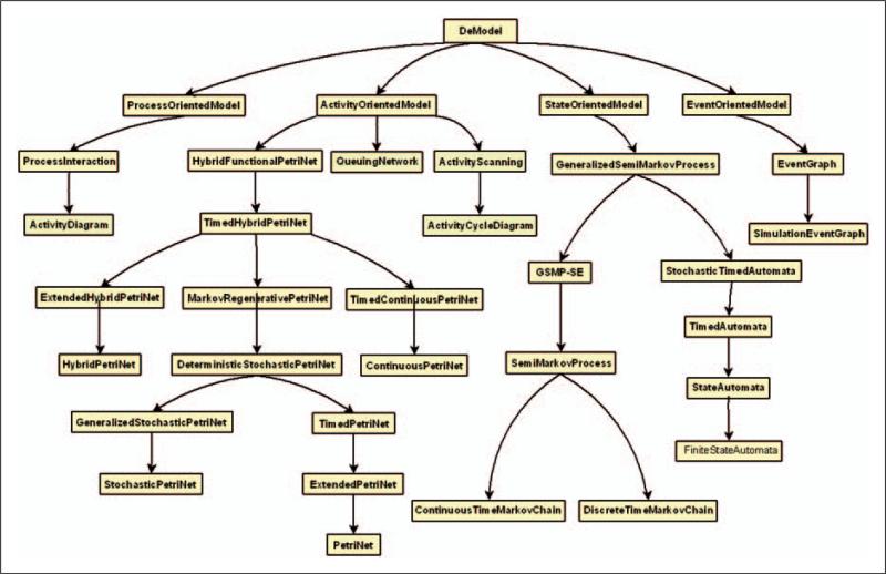
The discrete-event modeling taxonomy described by DeMO begins with the base class DeModel (discrete-event model). DeModel has four first-level subclasses, which are based on the principal of focal concept used by such models:
state-oriented model;
event-oriented model;
activity-oriented model;
process-oriented model.
Each of these subclasses describes a top-level modeling formalism and serves as a base class for a hierarchy of modeling techniques that exist under the particular formalism. The classes for the modeling techniques are created as subclasses of the modeling formalism classes. The hierarchy that exists under DeModel is shown in Figure 3. In order to specify a subclass that represents a modeling technique in detail, the properties inherited from its base class will have additional restrictions placed upon them, and additional properties may also be added. In the remainder of Section 3, we will discuss the four first-level subclasses of DeModel.
Figure 3.
DeMO's taxonomy of DES modeling formalisms and techniques.
3.3.2. DeMO State-oriented Model
State-oriented models modeling finite-state machines and Generalized Semi-Markov Processes (GSMPs) are widely used in computer science and M&S. The focal concept of such models is that of state. One is also interested in the causes of state changes as well as how the current state changes over time. In DeMO, state-oriented models are characterized by three sets, S, E, and T.
State space (S) – A model changes over time from state to state. Its current state at a particular time is quantified by the values of a collection of indicators, which record the properties of the model. The set of all possible combinations of these indicators is the model's state space, S.
Event set (E) – Events characterize the type of event instances that may occur. Event instances occur instantaneously at particular points in time and may cause state changes and/or future events. An event e ε E is enabled at time t1 and fires at time t2. The difference between t1 and t2 is the event lifetime. The combination of an event and its firing time is known as an even occurrence.
Time set (T) – A non-negative number represents the passage of time. Time t ε T is integer valued for discrete-time models and real valued (t ε R+) for continuous-time models.
In addition to the three sets above, we also use the following three functions in the definition of state-oriented models:
This is a Boolean function indicating which events a state enables. Enabling an event creates an instance of the event that is said to be active until it fires or is cancelled.
When an event instance is created, a clock timer is set and when it reaches zero, the event, unless it has been cancelled, fires.
The firing of events causes the model to change over time. The changes from the current state to the next states are determined by the state-transition function.
Note that a state-transition function may be depicted as a state-transition diagram where the nodes represent states and the edges represent events.
Let us look at the implementation of DeMO state-oriented models. All of DeMO's state-oriented models are rooted in a top-level abstract classed named StateOrientedModel, which has the basic properties listed in Table 2. Restrictions are placed upon the properties of this class in order to create the subclasses in the state-oriented model hierarchy.
Table 2.
Basic properties of DeMO StateOrientedModel class
| Property name | Property restriction (instance of) |
|---|---|
| has-StateSpace | DiscreteStateSpace |
| has-EventSet | FiniteEventSet |
| has-TimeSet | TimeSet |
| has-TransitionFunction | TransitionFunction |
| has-ClockFunction | ClockFunction |
| has-InitialState | InitialState |
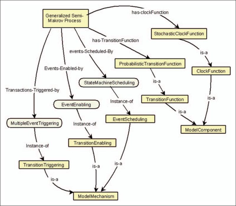
Consider, for example, the GSMP, the highest concrete class in the state-oriented model hierarchy. Part of its definition consists in placing further restrictions on the following properties:
ClockFunction is restricted to StochasticClockFunction TransitionFunction is restricted to Probabilistic TransitionFunction
In addition, the GSMP class uses the ModelMechanism instances shown in Table 3. Figure 4 shows a graphical representation of the GSMP class, its properties, and property restrictions.
Table 3.
ModelMechanism instances used by DeMO GSMP class
| Mechanism name | Value (instance) |
|---|---|
| TransitionTriggering | MultipleEventTriggering mechanism |
| TransitionEnabling | EventEnabling mechanism |
| EventScheduling | StateMachineScheduling mechanism |
Figure 4.
Graphical representation of GSMP portion of DeMO.
A restriction of the TransitionTriggering mechanism is the only difference between the GSMP and its subclass, Generalized Semi-Markov Process without Simultaneous-Events (GSMP-SE). The GSMP-SE class TransitionTriggering mechanism has a value of SingleEventTriggering instead of MultipleEvent Triggering, where SingleEventTriggering is defined to allow only a single event occurrence to trigger a transition. It is easy to see how other classes in the state-oriented models hierarchy can be defined using this same method. For instance, the StateAutomata class is defined by further restricting the ClockFunction and TransitionFunction classes inherited from its superclass. The ClockFunction is restricted to NoClock and TransitionFunction is restricted to Deterministic TransitionFunction. The hierarchical structure of the modeling techniques associated with DeMO StateOrientedModel class can be seen in Figure 3.
3.3.3. DeMO Activity-oriented Model
State-oriented models use the concepts of state, time, and event, and it is possible to conceive of state as an indicator of the model's configuration at a given point in time. Another way to think of state is in terms of location. For example, you may imagine that there is an entity (or token) moving around a model. The entity's current location marks the model's current state (as is the case with the animation of a Markov model). When multiple entities exist in the model, the relationship between state, location, and entity becomes more complex. In this situation, each entity must have a location, and the state must include this information in, for example, some type of state vector. One might attempt to record the locations of all entities currently in the model, but since the number of entities varies over time, the state vectors would need to vary in length. The vectors could be fixed length if a given number of places (or stations) could be specified at which entities reside, until an event (or events) occurs that causes them to move to other places. In such a case, the state of the model can be represented as a vector n:
where is the number of entities in place p ε P at time t. For the type of model mentioned above, it is also convenient to take a composite view of action. For example, service at a station in a Queuing Network may be thought of as an activity. Therefore, for activity-oriented models, the fundamental group of sets, (S, E, T), will change as follows: P will replace S and A will replace E to yield (P, A, T) as defined below.
Place Set (P) – A place is a location within a positional space (e.g. a metric space or topological space) indicating where a token is. Place p is a location within the model (e.g. logically at a node in a graph or physically in an n-dimensional coordinate system).
Activity Set (A) – An activity can be thought of as an atomic behavior and it usually happens over a time interval, which is delimited by a start event and an end event. Activities cause entities to move (or using PN terminology, transitions cause tokens to move from place to place).
Time set (T) – A non-negative number represents the passage of time. Time t ε T is integer valued for discrete-time models and real valued (t ε R+) for continuous-time models.
The implementation of activity-oriented models in DeMO begins with the abstract class ActivityOrientedModel. The basic properties of this class are listed in Table 4.
Table 4.
Basic properties of DeMO ActivityOrientedModel class
| Property name | Property restriction (instance of) |
|---|---|
| has-PlaceSet | FinitePlaceSet |
| has-ActivitySet | FiniteActivitySet |
| has-TimeSet | TimeSet |
| has-IncidenceFunction | IncidenceFunction |
| has-ClockFunction | ClockFunction |
| has-InitialState | InitialState |
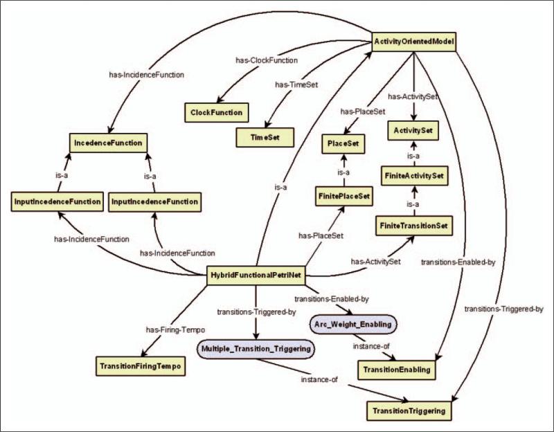
Restrictions may be placed on these and other properties in order to create subclasses of the ActivityOrientedModel class. The highest level concrete class in the activity-oriented model class hierarchy is the HFPN class. Part of the definition of this class consists of placing additional restrictions on the properties below:
ActivitySet is restricted to FiniteTransitionSet IncidenceFunction is restricted to InputIncidence Function and OutputIncidenceFunction InitialState is restricted to InitialMarking
In addition, the TransitionFiringTempo property is added to the HFPN class, and it uses the ModelMechanism instances shown in Table 5.
Table 5.
ModelMechanism instances used by DeMO HybridFunctionalPetriNet class
| Mechanism name | Value (instance) |
|---|---|
| TransitionTriggering | MultipleTransitionTriggering mechanism |
| TransitionEnabling | ArcWeightEnabling mechanism |
The set of arc weights in a PN model is similar to the state-transition function in our description of state-oriented models. The arc weights in conjunction with the place marking determine which transitions will be enabled. The transitions of a PN model correspond roughly to the state-transitions function of a state-oriented model in that their firing determines markings of the model places. The activity-oriented models also have an incidence function. This function establishes relationships between the places and transitions (activities) of a model. When a HFPN model is represented as a graph, the relationship is viewed as an arc between a place and a transition.
A graphical representation of the HFPN class and its properties can be seen in Figure 5. All other subclasses in the hierarchy are created by placing further restrictions on the properties inherited from this class and, in some cases, adding new properties.
Figure 5.
Graphical representation of DeMO activity-oriented model and Hybrid Functional PN model.
3.3.4. DeMO Event-oriented Model
It is often the case with state-oriented models that the size of the state becomes very large, while the number of distinct types of events remains relatively small. Given this situation one might consider turning that state-transition diagram into a smaller diagram where the nodes represent events instead of states. If this is done, the three primitive sets, (S, E, T), introduced in our discussion of state-oriented models still apply, but the focus will now be on events and the relationships between them.
The EGs4 modeling technique follows this approach, and SEGs62 provide an extended formal framework for EGs. SEGs are used as a top-level formalism for DeMO event-oriented models. A SEG depicts the causality between events. Each node in the directed graph represents an event, while arcs indicate how one event may influence another event. The arcs may also be labeled with conditions and time delays, and events (nodes) may have attributes (state variables) associated with them. State changes in an EG simulation model are made by assigning values to the state variables of the nodes. State space, S, need not be explicitly defined, as with state-oriented models, since the values of the state variables define the state of the system at a given point in time. In SEGs, sets of scheduling edges and canceling edges relate events to each other. If an event e1 is connected to an event e2 with a scheduling/canceling edge, it means that the occurrence of event e1 will prompt the scheduling/canceling of event e2. The notion of clock function presented in our discussion of state-oriented models corresponds to the edge delay times of SEGs, for example, if occurrence of event A schedules event B, then the edge connecting A and B may have a time delay t associated with it (i.e. event B is scheduled to occur t units after the occurrence of event A). The activation function and transition function in our description of state-oriented models roughly corresponds to the set of edge conditions and state-transition functions, respectively, for SEGs described by Schruben and Roeder.61 An edge condition along with the current event and the current state are used to determine the next event, while the set of state-transition functions determine the value of the state variables for each event node. EGs also specify a set of event priorities that are used to facilitate tie breaking for events that are scheduled to occur simultaneously.
The top-level abstract class for DeMO event-oriented models is EventOrientedModel and its basic properties are listed in Table 6.
Table 6.
Basic properties of DeMO EventOrientedModel class
| Property name | Property restriction (instance of) |
|---|---|
| has-EventSet | FiniteEventSet |
| has-IncidenceFunction | IncidenceFunction |
| has-TimeSet | TimeSet |
| has-ClockFunction | ClockFunction |
| has-InitialState | InitialState |
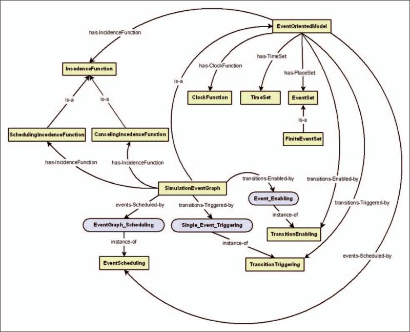
The highest level concrete class in the event-oriented model class hierarchy is the SimulationEventGraph class. Part of the definition of this class consists of placing additional restrictions on the property below:
IncidenceFunction is restricted to Scheduling IncidenceFunction and CancelingIncidenceFunction
The SimulationEventGraph class also uses the ModelMechanism instances shown in Table 7. Figure 6 shows a graphical representation of the SimulationEventGraph class, along with its property restrictions.
Table 7.
ModelMechanism instances used by DeMO SimulationEventGraph class
| Mechanism name | Value (instance) |
|---|---|
| TransitionTriggering | MultipleTransitionTriggering mechanism |
| TransitionEnabling | EventEnabling mechanism |
| EventScheduling | SimulationGraphScheduling mechanism |
Figure 6.
Graphical representation of DeMO event-oriented model and simulation event graph model.
3.3.5. DeMO Process-oriented Model
The PI world view is richer and more widely varied than the others, and consequently, developing a concise and adequate formalism is quite a challenge. There has been less work on formal definitions for PI than for the other world views. Zeigler40 describes a structured model for process interaction using elements of the DEVS formalism. Cota and Sargent57 modify PI to full encapsulation, while still allowing preemption of one process by another. Schriber and Brunner63 provide terminology for the world view where they discuss the transaction-flow approach to PI. Using their terminology, processes are described as transactions that are discrete units of traffic moving from point-to-point in a system, while competing with each other for resources. Silver et al.28 review the work of Zeigler, Cota and Sargent, and Schriber and Brunner as a starting point for the development of a PI ontology to be used for ontology-based representations of process-oriented models.
Following the ideas for the transaction-flow approach to PI, simulation models that conform to this world view may be described as having two types of components – active (processes) and passive (resources). Processes take actions that can change the state of the system, while resources are unable to directly take actions. A process can be thought of as being made up of a set of descriptive variables, a time left in the current state, and a set of computation segments. Each of a process’ computation segments consists of a condition C under which the segment will be activated, an activation function f that determines the actions to be taken when the segment is activated, and a label l, which points to the first statement of the segment. In our presentation of state-oriented models, we introduced three primitive sets, (S, E, T), and we discussed how these sets are used in each of the models, state-oriented, activity-oriented, and event-oriented, addressed so far. Applying the use of these sets to process-oriented models is more diffcult, but we will attempt to illustrate some rough correspondences between the use of the sets in the process-oriented model and the other models.
The state space, S, is not explicitly defined in a PI model, but the descriptive variables of the process define the state of the system at a particular point in time. Events are also not explicitly defined in PI models; however, we draw a correspondence between events, activities, and the computation segments of a process. The computation segment of a process can be viewed as an analogy of an event in that it occurs at a fixed point in time and may cause the state of the system to change.
Presenting a basic algorithm for PI simulation is helpful in clarifying the role played by the components of a model. We describe such an algorithm here. When a simulation begins, activation notices are placed onto a list known as a Future Activations List (FAL). Each notice contains a process, the reactivation time of the process, and a label value representing the reactivation point of the process. The FAL is ordered by reactivation time. It is then processed in sequential order by removing the first activation notice, which contains the current process. The simulation clock is set to the current process’ reactivation time and execution of the process begins at the computation segment specified by the reactivation point. If the condition C associated with the segment evaluates to true, the segment's activation function, f, is applied. Among other things, f may change the state of the system and schedule activation notices for the process or other processes that it influences.
The top-level abstract class associated with the process-oriented models in DeMO is the ProcessOrientedModel class, which has the basic properties listed in Table 8.
Table 8.
Basic properties of DeMO ProcessOrientedModel class
| Property name | Property restriction (instance of) |
|---|---|
| has-ProcessTypes | Process |
| has-TimeSet | TimeSet |
| has-ClockFunction | ClockFunction |
| has-InitialState | InitialState |
The basic properties of the ProcessOrientedModel class are few compared to the classes that represent the other DES world views. The reason for this is that process-oriented models are defined primarily by defining processes and the process activities (computation segments) of processes. Since this is the case, many of the details of DeMO ProcessOrientedModel class are addressed via properties of the Process and ProcessActivity classes, rather than by properties of the ProcessOrientedModel class. Given this situation, we present the basic properties of the Process and ProcessActivity classes in the Table 9, while the ModelMechanism instances for the ProcessOriented Model class are shown in Table 10.
Table 9.
Basic properties of DeMO Process and ProcessActivity classes
| Process class property name | Property restriction (instance of) |
|---|---|
| has-ProcessActivity | ProcessActivity |
| ProcessActivity class property name | Property restriction (instance of) |
|---|---|
| is-Supported-by | Resource |
| has-Input-Transport | Transport |
| has-Output-Transport | Transport |
Table 10.
ModelMechanism instances used by DeMO ProcessOrientedModel class
| Mechanism name | Value (instance) |
|---|---|
| TransitionTriggering | ProcessTriggering mechanism |
| TransitionEnabling | ProcessEnabling mechanism |
| EventScheduling | ProcessInteractionScheduling mechanism |
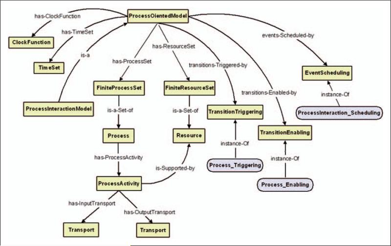
A PI model can be visualized as a collection of directed graphs, where each type of process in the model is represented as a graph. Using the classes above, we can describe the basic structure of a model. A PI model is made up of different types of processes. Each process is a directed graph whose vertices are ProcessActivities and edges, which link the ProcessActivities, are Transports.
The highest level concrete class in DeMO process-oriented model hierarchy is the ProcessInteraction class. Figure 7 shows a graphical representation of the ProcessOrientedModel, ProcessInteraction, Process, and ProcessActivity classes along with some of their primary property restrictions. For more details on process-oriented models see Silver et al.28
Figure 7.
Graphical representation of DeMO process-oriented model and process-interaction model.
4. Applications of DeMO
Ontologies may be thought of as knowledge repositories for specific domains; as an ontology for the domain of discrete-event modeling, DeMO should specify the concepts used in the domain as well as the relationships between the concepts. It does this by providing a collection of knowledge concepts about existing DES formalisms; and while the range of formalisms described in DeMO is representative rather than exhaustive, it is possible (at least in principle) to insert any DES formalism into the ontology. Given the purpose of the ontology, we believe that it will ultimately be judged by the benefits that it brings to the M&S community. It is, therefore, important that the ontology be made available to this community. This has been done by placing DeMO on the Web. The presence of DeMO on the Web provides a centralized machine-readable knowledge repository for discrete-event M&S that can be used by either modelers or computer applications in a variety of ways. Having this knowledge available via the Internet may be a useful step in the evolution of Web-based M&S, and the ontology itself may grow and evolve through the efforts of the M&S community. In this section, we present some current ways in which DeMO is being used for M&S, and we explore some potential future uses of the ontology. In time, we expect new uses of DeMO to emerge based on the needs of modelers and the demands of different applications.
4.1. Ontology-driven Modeling and Simulation
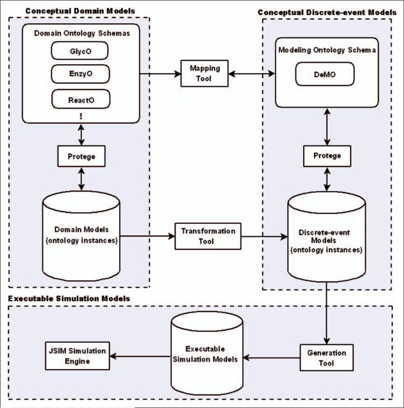
ODS aligns the knowledge resident in domain ontologies with the knowledge resident in a modeling ontology in order to expedite the development of simulations. The methodology presented uses the DeMOforge tool (see Figure 8) to support a three phase approach to ODS. Each of the phases, (1) ontology mapping, (2) model transformation, and (3) model generation, is described below.
Figure 8.
DeMOforge architecture.
ODS allows ontologies to drive the creation of a DES model by integrating the knowledge resident in domain ontologies with the knowledge resident in a modeling ontology and then transforming the results into an executable simulation model. One method for achieving this is to have the simulation software packages and the domain ontologies logically linked via a common DES ontology (i.e. DeMO). The mapping phase of ODS lays the foundation for these logical links. During this phase, domain ontology concepts are mapped to concepts and relationships in DeMO to create correspondences between the components of the domain ontologies and the modeling ontology. These correspondences are used during the model transformation phase to provide a conduit through which syntactically compatible and semantically meaningful knowledge from the domain ontologies is transferred to DeMO ontology. For example, models of biochemical pathways have been built using instances of the Reaction Ontology (ReactO; http://glycomics.ccrc.uga.edu/core4/informatics-ontologies.html), and these instances have been transformed into DeMO instances that represent the system as a conceptual model that conforms to a specific DES world view (activity-oriented) and modeling technique (Hybrid PNs). By allowing the parts of a model to be stored as instances of DeMO classes, we are able to accurately represent the model in a way that is independent of the simulation code. Pace64 defines a conceptual model as the collection of information that describes a simulation developer's concept about a simulation and its parts. We take this view when we consider a collection of ontological instances to be a form of conceptual model. During the model generation phase of ODS, DeMO instances created in the transformation phase are used to generate an executable simulation model.
The DeMOforge ODS tool29 was developed to support the ODS process described above. The tool, whose architecture is shown in Figure 8, supplies modules to support each of the phases of ODS. In this section, we provide an overview of the tool and give an example of its use in the domain of biochemistry. DeMOforge supports the mapping phase of ODS by providing a facility for creating mappings between domain ontologies and DeMO. On a technical level, these mappings are similar to the mappings that often occur between domain ontologies, but their purpose is different. The mappings that typically occur between domain ontologies are used to establish relationships (i.e. equivalence and subsumption) between multiple concepts.65 For example, one ontology may use the term ‘automobile’ and another may use the term ‘car’ to describe the same concepts. Entities that use these ontologies need to understand that both of these terms refer to the same concept. An accepted way of facilitating this understanding is to create a mapping between the terms that specifies that the ‘automobile’ and ‘car’ are equivalent. DeMOforge creates mappings between domain ontologies and a modeling ontology, rather than between domain ontologies, and the concepts being mapped by the tool do not necessarily have obvious relatedness. An example of this can be seen in the mappings created between ReactO and DeMO in order to drive the simulation of biochemical pathways. ReactO classes and properties used in the representation of biochemical pathways have been mapped to DeMO classes that are used in the representation of HFPN models.
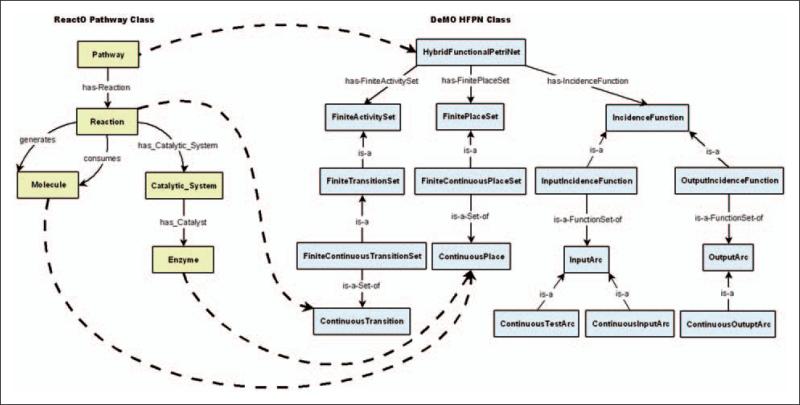
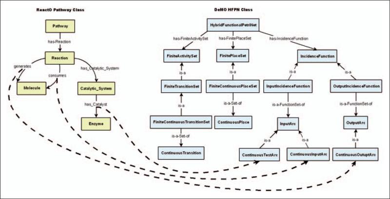
Figures 9 and 10 show graphs of the classes and property relationships that make up a ReactO Pathway and a DeMO HFPN. The dashed lines in Figure 9 indicate mappings between ReactO and DeMO classes. For example, since a biochemical pathway may be represented as a HFPN for purposes of simulation, the ReactO Pathway class is mapped to DeMO HFPN class. You will notice in Figure 9 that the ReactO Pathway is made up of several classes that are related to the Pathway class via properties. Since this is the case, we must map the relevant classes used to represent a ReactO Pathway to appropriate DeMO classes, as indicated by the dashed lines in the figure. For example, because the ReactO Reaction class is related to the ReactO Pathway class, the Reaction class is mapped to the appropriate DeMO class. Knowing that in a HFPN a reaction is often represented as a continuous transition, a developer may create a mapping between the Reaction class of ReactO and the ContinuousTransition class of DeMO, specifying that a biochemical reaction corresponds to a continuous transition for the purpose of DES.
Figure 9.
Mappings between ReactO pathway and DeMO HFPN classes.
Figure 10.
Mappings between ReactO properties and DeMO classes.
In addition to mapping classes between ontologies, DeMOforge is also capable of mapping properties to classes. A property (or more specifically an object property) in an ontology typically establishes a relationship between two entities, most often two classes. For instance, the ReactO has-Reaction property is used to create a relationship between the ReactO Pathway class and the ReactO Reaction class. This creates a subject-predicate-object triple, where the Pathway class is the subject, the has-Reaction property is the predicate, and the Reaction class is the object. Given the nature of property usage, DeMOforge allows triples rather than single properties to be mapped. The dashed lines in Figure 10 indicate mappings between triples in ReactO and classes in DeMO. Consider the ReactO Reaction → consumes → Molecule triple. The consumes property is used in this triple to establish a relationship between the ReactO Reaction and Molecule classes. In order to support the development of a DeMO-based HFPN model, this triple needs to be mapped to DeMO ContinuousInputArc class.
Mapping domain ontology property triples to DeMO classes frequently causes DeMOforge to generate rules to be stored along with the mapping. The rules are used by DeMOforge during the ODS transformation phase to generate property relationships among DeMO instances. An example of this rule generation can be seen in the mapping of the ReactO Reaction → consumes → Molecule triple to ContinuousInputArc class. When the mapping is created, DeMOforge checks to see if the ContinuousInputArc class has property relationships with DeMO ContinuousPlace and Continuous Transition classes. DeMOforge determines that it needs to check for these relationships because mappings currently exist between the ReactO Molecule class and DeMO ContinuousPlace class and between the ReactO Reaction class and DeMO ContinuousTransition class. Upon performing this check, DeMOforge finds that the ContinuousInputArc class is related to the ContinuousPlace class via the has-Source-Place property and to the ContinuousTransition class via the has-Target-Transition property. Given this information, DeMOforge generates rules to be stored with the mapping which state that the has-Source-Place and has-Target-Transition properties should be used when ContinuousInputArc instances are created during the ODS transformation phase.
Tables 11 and 12 show the mappings between ReactO and DeMO that were created in order to facilitate simulation of biochemical pathway models. Table 11 shows the class-to-class mappings, while Table 12 shows the property-to-class mappings and related rules.
Table 11.
Mappings between corresponding ReactO and DeMO classes
| ReactO class | DeMO class |
|---|---|
| Pathway | HybridFunctionalPetriNet |
| Reaction | ContinuousTransition |
| Molecule | ContinuousPlace |
| Enzyme | ContinuousPlace |
Table 12.
Mappings between corresponding ReactO properties and DeMO classes
| ReactO property | DeMO class | Transformation rule |
|---|---|---|
| Reaction consumes Molecule | ContinuousInputArc | use has-Source-Place property, use has-Target-Transition property |
| Reaction generates Molecule | ContinuousOutputArc | use has-Source-Transition property, use has-Target-Place property |
| Reaction has-Catalyst Enzyme | ContinuousTestArc | use has-Source-Place property, use has-Target-Transition property |
The Transformation Module of DeMOforge translates instances of domain ontology classes into instances of DeMO classes that are used to represent a conceptual DES model. We will illustrate this using an example in which a portion of an N-Glycan biosyntheses pathway as represented via ReactO instances is transformed into DeMO instances, which are used to represent the pathway as a HFPN. An N-Glycan is an oligosaccharide (i.e. a carbohydrate consisting of at least two sugar units) that is linked to a glycoprotein by attachment to the amide nitrogen of an asparagine residue.
In this example, the DeMOforge transformation tool is used to retrieve pre-existing instances of ReactO classes that represent an N-Glycan pathway. The tool then uses these instances along with the mappings shown in Tables 11 and 12 to create instances of DeMO classes, which taken together can be viewed as a conceptual HFPN model of the same pathway. The tool makes use of SWRL rules to accomplish the transformation. The following steps give a brief outline of the process.
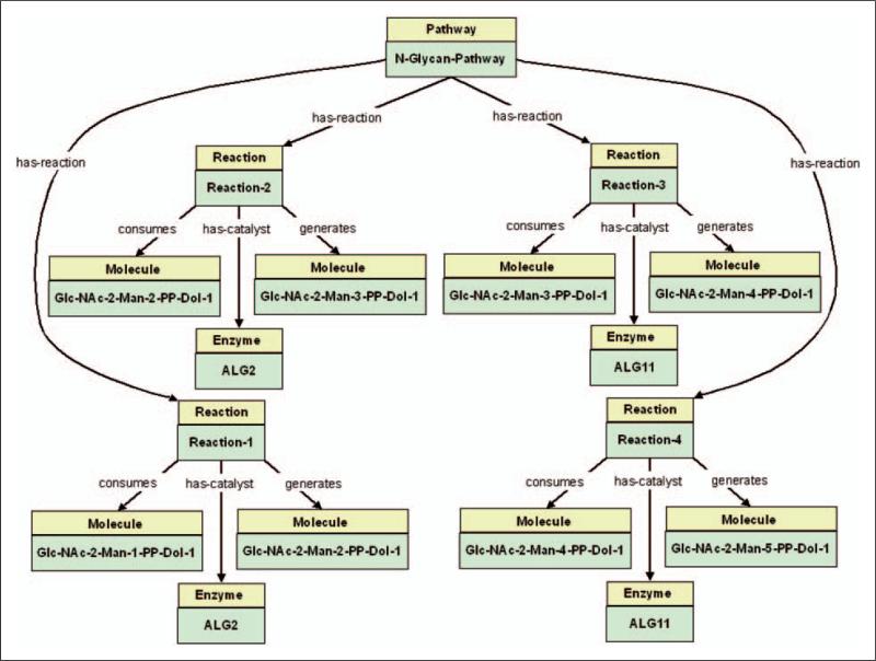
SWRL queries are generated and used to retrieve the ReactO instances that represent the pathway model. Given the ReactO Pathway instance that represents the N-Glycan pathway, the query uses property relationships to traverse the instance graph and place instances that represent the pathway in a data structure for further processing. An example of these instances can be seen in of Figure 11.
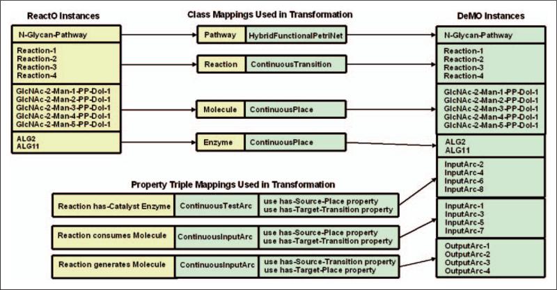
Previously defined class mappings are used to create DeMO instances that correspond to the ReactO instances retrieved in Step 1. For example, the mapping between the ReactO Molecule class and ContinuousPlace class is used to transform a ReactO Molecule instance named GlcNAc-2-Man-1-PP-Dol-1 into a DeMO ContinuousPlace instance of the same name. The class mappings are shown in the center of Figure 12, while DeMO instances can be seen on the right side of the figure.
The property mappings (see bottom left of Figure 12) along with their associated rules are used to create additional DeMO instances and to establish property relationships among them. An example of this can be seen in the creation of instances for DeMO ContinuousInputArc class as described in the steps below.
The property mapping between the ReactO triple Reaction → consumes → Molecule and DeMO ContinuousInputArc class is retrieved and used to drive the creation of ContinuousInputArc instances.
Since the Reaction → consumes → Molecule triple has Reaction as its domain, DeMOforge will read each ReactO Reaction instance in the pathway and create analogous DeMO ContinuousInputArc instances, as shown in Figure 13.
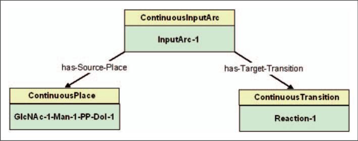
DeMOforge uses the rules associated with the mapping along with the property relationships defined for the DeMO ContinuousInputArc class to create additional instances and establish relationships between them. For example, the ‘use has-Source-Place property’ and ‘use has-Target-Transition property’ rules will cause a DeMO ContinuousPlace instance and a ContinuousTransition instance to be created for each ContinuousInputArc instance in Figure 13. These rules will also cause a Continuous Place instance and a ContinuousTransition instance to be linked to each ContinuousInputArc instance via property relationships. Figure 14 shows one ContinuousInputArc instance and its property relationships.
Figure 11.
Graph of ReactO instances representing an N-Glycan pathway.
Figure 12.
Mappings used and instances created during the ODS transformation phase for an N-Glycan pathway.
Figure 13.
ReactO Reaction instances and analogous DeMO ContinuousInputArc instances.
Figure 14.
Example of DeMO ContinuousInputArc instance and its relationship to a ContinuousPlace and a ContinuousTransition instance.
Once the DeMOforge transformation process is complete, that is all relevant ReactO instances, mappings and rules have been processed in order to create DeMO instances, the N-Glycan pathway model originally represented as a collection of ReactO instances will have been transformed into a HFPN-based N-Glycan pathway model represented as a collection of DeMO instances.
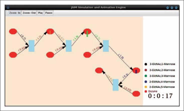
After transformation is complete, DeMO instances, which represent a conceptual DES model, are used to generate an executable simulation model. In the case of the example discussed above, the instances that represent a HFPN model of the N-Glycan pathway are used to generate an executable pathway simulation. The generation of the executable model is accomplished using the DeMOforge generation module. This module uses category-specific code generators to translate DeMO instances into an executable model. In our example, an executable HFPN model for the JSIM simulation environment6 was produced by a generator using the following steps: (1) the OWL 2.2.0 application programming interface (API)66 was used to read through DeMO instances and populate a data structure with a graph-based representation of the model; (2) the scenario management component of the generator determined that additional information was required for the particular scenario under which the simulation was to be executed, and it requested user input for the location of sources from which data was to be retrieved; (3) the information collected in the previous two steps was used to produce a JSIM-based HFPN model. The runtime animation of the model is shown in Figure 15.
Figure 15.
JSIM simulation environment's animation of N-Glycan pathway simulation.
4.2. Additional Applications
While much of the work related to the application of DeMO ontology up to this point has focused on ODS, work on the use of DeMO in other applications areas is also underway. These include model discovery, models reuse, and formalized documentation of the model development process.
4.2.1. Model Discovery
DeMO ontology, once populated with conceptual models, acts as a repository that is able to categorize models in a variety of different ways for purposes of model discovery. DeMO-based conceptual models can be searched for by DES formalism (or modeling technique) or by terms from domain ontologies to which DeMO-based models maintain links. As mentioned earlier, DeMO-based conceptual models created using the DeMOforge ODS tool maintain links to classes in the domain ontology that was used to drive their creation. For example, if ReactO has been used to drive the creation of a DeMO-based HFPN model of a particular biochemical pathway, the links that DeMO-based model maintains to ReactO may be used during model discovery. Given the presence of the links in DeMO, a search tool can use terms from ReactO to search for DeMO-based model. Suppose that a biochemical researcher is searching for a pathway model that uses a particular enzyme that exists in ReactO. The researcher may use this knowledge, which resides in ReactO, to search for HFPN models that use the enzyme. Since DeMO-based HFPN pathway models will maintain links to enzyme information in ReactO, the search may lead to the discovery of DeMO-based models that use the enzyme.
DeMO can also be used to support the discovery of executable simulation models that are available either locally or via the Web. Executable models created using the DeMOforge tool or by other means should conform to DeMO ontology as well as to the relevant domain ontologies. In addition, these executable models should use naming conventions that conform to these ontologies, and they may also maintain annotations (meta-data) about the ontological knowledge used during model generation. Search tools can use the ontological information embedded within the executable models for purposes of model discovery. From a Web point of view, discovering executable models is roughly analogous to discovering semantically annotated Web services.
4.2.2. Model Reuse
One of the primary reasons for model discovery is model reuse. DeMO-based conceptual models can be reused by allowing the scenario management facility of the DeMOforge tool to change input parameters and translate the conceptual models into executable models that use different input. While the ability to discover and reuse DeMO-based models under different scenarios is important, the ability to use DeMO-based models (or portions of models) as components in the development of other models is an equally important issue. According to Teo and Szabo,18 the four main steps in component-based simulation development are: (1) model discovery; (2) model reuse; (3) syntactic composition; and (4) semantic composition. We have seen how DeMO may be used to support model discovery and reuse; we will now briefly discuss how DeMO may be used to support composition.
Work is currently in process to add hierarchical modeling capabilities to DeMO. The hierarchical modeling capability will allow conceptual models to be redefined as model components. This is accomplished using the CompositeComponent subclass of DeMO ModelComponent class. The idea is that a DeMO-based conceptual model will be wrapped in a model component, allowing it to act as a component of another model. The CompositeComponent class has the properties shown in Table 13.
Table 13.
Properties of DeMO CompositeComponent classes
| Property name | Property restriction (instance of) |
|---|---|
| has-Wrapped-Model | DeModel |
| has-ComponentMapping | Activity or Place |
| has-InputPort | SourceActivity or Place |
| has-OutputPort | SinkActivity or Place |
The has-Wrapped-Model property specifies the model instance that is to be wrapped as a model component. The has-ComponentMapping property allows the wrapped model to be linked to a specific instance of the ModelComponent class, which indicates the type of model component that the model represents. For example, a conceptual model that is an instance of the ProcessInteractionModel class may be wrapped by an instance of the CompositeComponent class and have a has-ComponentMapping property, which indicates that it is to be considered an instance of the ProcessActivity class for purposes of model composition. The has-InputPort and has-OutputPort properties are used to describe how data will enter and exit the model when it is treated as a component.
Hierarchical modeling facilities are currently under development for DeMO ProcessInteractionModel and ActivityOrientedModel classes and will be integrated into the StateOriented and EventOriented model classes in the future. When a PI model is redefined as a model component, the has-Wrapped-Model property of the CompositeComponent instance, which represents the model, will have as its value an instance of the ProcessActivity class. The ProcessActivity instance will act as a proxy for the model when it is used as a component in other PI models. The value of the has-InputPort property will be a Source ProcessActivity instance of the original PI model, and the value of the has-OutputPort property will have as its value a Sink ProcessActivity instance of the original model. The has-Transport property, which acts as a connector between PI Activity instances, of the proxy activity will be used to connect the CompositeComponent instance to other Activity instances in the hierarchical model.
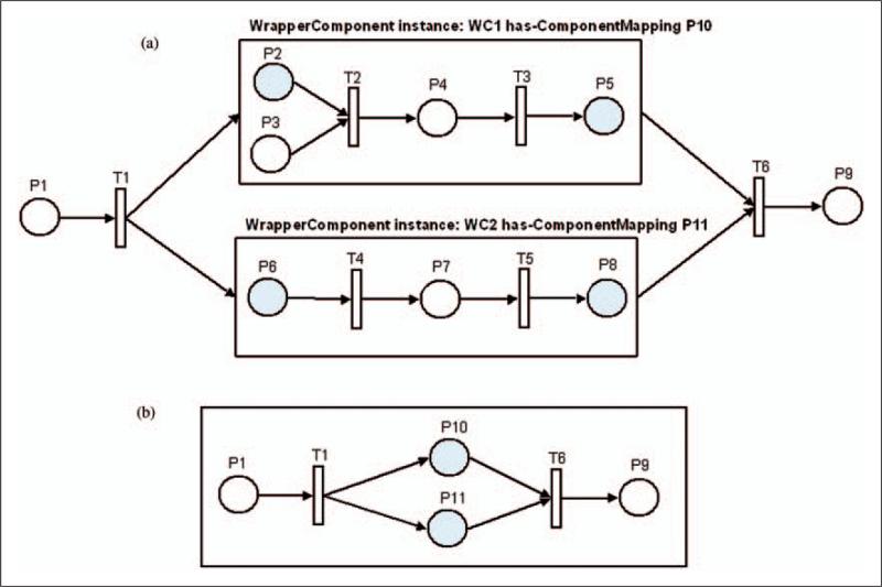
When a PN model is redefined as a model component using a CompositeComponent instance, its has-Wrapped-Model property will have an instance of the Place class as its value. The Place instance will act as a proxy for the model when it is used as a component in other models. The has-InputPort property value of the CompositeComponent instance will have a Place instance from the original model as its value, and the has-OutputPort property will also have a Place instance from the original model as its value. A Transition instance, along with its has-InputArc and has-OutputArc properties, will be used to connect the CompositeComponent instance to the other places in the PN model. In Figure 16, two PN models have been redefined as components using Composite Component instances named WC1 and WC2. The has-ComponentMapping property of WC1 contains a Place instance named P10, and the has-ComponentMapping property of WC2 contains a Place instance named P11. Figure 16(a) shows a graphical view of a PN model that uses the WC1 and WC2. Figure 16(b) shows a graphical view of the same PN model when the proxy places are used in place of WC1 and WC2.
Figure 16.
PN model using hierarchical capabilities of DeMO. (a) A graphical view of how the original models fit into the PN model when they are redefined using the CompositeComponent class. The shaded places serve as input or output ports. (b) A graphical view of the PN models in (a) with the proxy places used to represent the original models.
While the hierarchical modeling facilities currently under development will support limited component-based model development at the syntax level, issues such as semantic composability and parallel execution of models remain as future work.
4.2.3. Formalized Documentation of the Model Development Process
In addition to the mappings used to support ODS described in Section 4.1, DeMO has the ability to store mappings between DeMO instances that represent a conceptual DES model and the domain ontology instances that were used by ODS to create the conceptual model. DeMO also has the ability to store mappings to external resources that provide information about the modeling process and application domain for which the conceptual model was created. These mappings are stored as properties of DeMO DomainInstance-Mapping class. Every subclass of DeMO's top-level model class (DeModel) and top-level model component class (ModelComponent) contains a has-DomainInstance-Mapping property. This allows all DeMO model instances and all model component instances to store mappings to domain ontology instances and external resources.
The mappings between DeMO instances and domain ontology instances can be automatically created by the DeMOforge tool during the ODS transformation phase. If information about external resources is available in the domain ontologies, it may also be transferred to DeMO during the transformation phase; otherwise, mappings to external resources may be added to DeMO by the model developer.
Because DeMO-based conceptual model has links to information about the domain for which it was created, it may be used to generate model documentation, for example in the form of a report or an annotated graphical representation of the conceptual model. The conceptual model's links to domain information may also be passed to the executable model during the generation phase of ODS, as described below.
Since conceptual DES models represented as DeMO instances are used during the ODS generation phase to create an executable model, the domain ontology instances and external resource mappings can be passed along to executable models. Making this information available to executable models opens up several possibilities. For example, Section 4.1 describes ODS of a biochemical pathway. In this example, ODS takes a biochemical pathway described using ReactO instances and transforms it into a conceptual HFPN model represented as DeMO instances. This DeMO-based conceptual model is then used to generate an executable model. In ReactO, one of the pathway's enzymes is represented as an instance of ReactO Enzyme class. In DeMO, the same enzyme is represented as an instance of the ContinuousPlace class. When ODS generates the executable model, mapping information that resides with DeMO ContinuousPlace instance can be passed to the executable model. Once the mapping information is available to the executable model, it may be used in a variety of ways. For instance, during animation of the simulation a user may mouse over the continuous place, which represents the enzyme, and the simulation may use the mapping information to access ReactO and display information about the enzyme.
5. Conclusions and Future Work
In this paper we present DeMO. DeMO is a general purpose DES ontology, which represents the domain of discrete-event modeling by describing the classic DES world views as well as many of the formalisms and modeling techniques that conform to the world views. Since DeMO was developed using OWL and is easily accessed via the Internet, our hope is that it might be used to support the increasing collaborative work among the M&S community.
The paper also proposes DeMO version of ODS, and discusses its practical implementation, which is realized in the development of the DeMOforge tool. The primary contribution of this approach to ODS is that it allows the knowledge resident in domain ontologies and a modeling ontology to drive the creation of executable simulation models. DeMOforge uses a three phase approach to ODS. This approach allows executable simulation models to be generated from conceptual models developed using knowledge resident in domain ontologies. In addition, we present other ways in which DeMO may be used to support M&S, such as: (1) supporting model discovery via searches by modeling technique/formalism or domain ontology concept; (2) supporting model reuse and component-based model development; and (3) providing formalized documentation of the model development process as a byproduct of ODS.
Future work includes making enhancements to DeMO to more fully support hierarchical and component-based model development, and addressing issues such as semantic composability. We are also planning to modify the ontology to include modeling techniques, such as Colored PNs, not supported by the current version. In future versions of the DeMOforge tool, we plan to include facilities to provide ODS for state-oriented and event-oriented modeling techniques, to provide a mechanism that allows DeMO-based conceptual models to be transformed from one modeling technique to another, and to replace logic currently encoded using the SWRL with logic that uses languages associated with RIF, a new emerging standard.
6. Funding
This research is supported in part by the Integrated Technology Resource for Biomedical Glycomics (5 P41 RR18502-02) funded by the National Institutes of Health – National Center for Research Resources.
Biography
Gregory A Silver is an Assistant Professor of Computer Information Systems at Anderson University. He received his BBA and MS in Computer Information Systems from Georgia State University in 1984 and 1996, respectively, and is currently a PhD candidate in Computer Science at the University of Georgia (UGA). His research interests include simulation, and distributed systems.
John A Miller is a Professor of Computer Science at the UGA and has also been the Graduate Coordinator for the department for nine years. His research interests include database systems, simulation, Web services, and bioinformatics. Dr Miller received a BS in Applied Mathematics from Northwestern University in 1980 and an MS and PhD in Information and Computer Science from the Georgia Institute of Technology in 1982 and 1986, respectively. As part of his co-operative undergraduate education program, he worked as a Software Developer at the Princeton Plasma Physics Laboratory. In his areas of interest, Dr Miller has authored of over 150 research papers. He is an Associate Editor for the ACM Transactions on Modeling and Computer Simulation, IEEE Transactions on Systems, Man and Cybernetics and Simulation: Transactions of the Society for Modeling and Simulation International, as well as an Editorial Board Member for the Journal of Simulation and International Journal of Simulation and Process Modeling.
Maria Hybinette is a researcher and associate professor in high performance simulation systems in the Computer Science Department at the UGA. Her current focus is on social animal behavior modeling and financial market simulation. She is particularly interested in hybrid (both micro and macro) simulation of multi-agent behavior, and mechanisms for making them faster, more effective, and more usable. In earlier work, she developed a number of methods for boosting the performance of DESs on parallel multi-processors. She completed her PhD at Georgia Institute of Technology. She was a staff simulation and modeling engineer at the MITRE Corporation. She now directs the Distributed Simulation Lab at UGA.
Gregory Baramidze is a PhD candidate at the Computer Science Department working with the Computational Systems Biology Lab at the UGA. He is also currently affiliated with the Department of Mathematics at Western Illinois University. His interests include computational biology and simulation and modeling.
William York is Associate Professor of Biochemistry and Molecular Biology, and Adjunct Associate professor of Computer Science and Plant Biology at the UGA. He received his BA in molecular, cellular, and developmental biology in 1978 at the University of Colorado and his PhD in biochemistry and molecular biology in 1996 from the UGA. He was senior research chemist at the Complex Carbohydrate Research Center at the UGA from 1985 to 1996. Dr York's diverse research interests include the development and application of spectroscopic and computational methods for the analysis of complex carbohydrates, the development of bioinformatic tools to study the roles of carbohydrates in living systems, and the use of these tools to develop realistic models describing the assembly and morphogenesis of the ‘primary cell walls’ of higher plants.
References
- 1.Lackner MR. Toward a general simulation capability; Proceedings of the AFIPS Spring Joint Computer Conference.1962. pp. 1–14. [Google Scholar]
- 2.Kiviat PJ. Digital computer simulation: computer programming languages. RAND Memo RM-5883-PR. 1969 [Google Scholar]
- 3.Petri CA. Fundamentals of a theory of asynchronous information flow; Proceedings of IFIP Congress.1962. pp. 386–390. [Google Scholar]
- 4.Schruben L. Simulation modeling with event graphs. Comm ACM. 1983;26:957–963. [Google Scholar]
- 5.Fishwick PA. Web-based simulation: Some personal observations; Proceedings of the 1996 Winter Simulation Conference.1996. pp. 772–779. [Google Scholar]
- 6.Nair R, Miller JA, Zhang Z. A Java-based query driven simulation environment; Proceedings of the 1996 Winter Simulation Conference.1996. pp. 786–793. [Google Scholar]
- 7.Page EH, Fishwick PA, Healy KJ, Nance RE, Paul RJ. Web-based simulations: revolution or evolution. ACM Trans Model Comput Simulat. 2000;10:3–17. [Google Scholar]
- 8.Miller JA, Fishwick PA, Taylor SJ, Benjamin P, Szymanski B. Research and commercial opportunities. Web-based Simulation. Simulat Pract Theor. Special Issue on Web-Based Simulation. 2001;9:55–72. [Google Scholar]
- 9.Jungel K, Kindler E, Weber M. The Petri net markup language. Petri Net Newsl. 2000;59:24–29. [Google Scholar]
- 10.Fishwick PA. RUBE: an XML-based architecture for 3D process modeling and model fusion; Proceedings of Enabling Technology for Simulation Science, Part of SPIE Aerosense ’02 Conference.2002. pp. 330–335. [Google Scholar]
- 11.Fishwick P. Using XML for Simulation Modeling; Proceedings of the 2002 Winter Simulation Conference.2002. pp. 616–622. [Google Scholar]
- 12.Berners-Lee T, Hendler J, Lassila O. The Semantic Web. Sci Am. 2001;284:34–43. [Google Scholar]
- 13.Lacy L. [17 March 2010];Semantic web applications for modeling and simulation. http://www.daml.org/2001/07/dmso-pplications/semantic-web-071101ppt, (2001) [Google Scholar]
- 14.Gruber T. A translation approach to portable ontology specifications. Knowl Acquis. 1993;5:199–220. [Google Scholar]
- 15.Miller J, Baramidze G, Fishwick P. Investigating ontologies for simulation and modeling; Proceedings of the 37th Annual Simulation Symposium.2004. pp. 55–71. [Google Scholar]
- 16.Tolk A. Evaluation of the C2IEDM as an interoperabilityenabling ontology; European Simulation Interoperability Workshop.2005. [Google Scholar]
- 17.Lacy LW. PhD Dissertation. Department of Industrial Engineering and Management Systems, University of Central Florida; 2006. Interchanging discrete-event simulation process-interaction models using the web ontology language – OWL. [Google Scholar]
- 18.Teo Y, Szabo C. CODES: An integrated approach to composable modeling and simulation; Proceedings of the 41st Annual Simulation Symposium.2008. pp. 103–110. [Google Scholar]
- 19.Yilmaz L, Paspuleti S. Toward a meta-level framework for agent-supported interoperation of defense simulations. J Defense Model Simulat. 2005;2:161–175. [Google Scholar]
- 20.Zeigler BP, Praehofer H, Kim TG. Theory of modeling and simulation. Integrating discrete event and continuous complex dynamic systems. Academic Press; San Diego, CA: 2000. [Google Scholar]
- 21.Zeigler B, Mittal S, Xu H. Towards a formal standard for interoperability in M&S/system of systems integration; Proceedings of GMU-AFCEA Symposium on critical Issues in C4I.2008. [Google Scholar]
- 22.Lacy LW, Gerber WJ. Potential modeling and simulation applications of the web ontology language – OWL; Proceedings of the 2004 Winter Simulation Conference; Washington DC. 2004. pp. 265–270. [Google Scholar]
- 23.McGuinness D, Harmelen F. [12 June 2009]; OWL Web Ontology Language overview, http://www.w3.org/TR/owl-features (2003) [Google Scholar]
- 24.Tolk A, Muguria J. The levels of conceptual interoperability model; Proceedings of the 2003 Simulation Interoperability Workshop.2003. pp. 14–19. [Google Scholar]
- 25.Tolk A. Composable mission spaces and M&S repositories – applicability of open standards. Spring Simulation Interoperability Workshop. 2004 [Google Scholar]
- 26.Turnitsa CD. Extending the levels of conceptual interoperability model (LCIM); Proceedings of the IEEE Summer Computer Simulation Conference.2005. [Google Scholar]
- 27.Zeigler BP, Hammonds PE. Modeling & simulation-based data engineering: introducing pragmatics into ontologies for net-centric information exchange. Academic Press; San Diego, CA: 2007. [Google Scholar]
- 28.Silver GA, Lacy LW, Miller JA. Ontology based representations of simulation models following the process interaction world view; Proceedings of the 2006 Winter Simulation Conference.2006. pp. 1168–1176. [Google Scholar]
- 29.Silver GA, Bellipady K, Miller J, York W, Kochut K. Supporting interoperability using the Discrete-event Modeling Ontology (DeMO); Proceedings of the 2009 Winter Simulation Conference.2009. pp. 1399–1410. [Google Scholar]
- 30.Benjamin P, Graul M. A framework for adaptive modeling and ontology-driven simulation; Proceedings of the SPIE, Enabling Technologies for Simulation Science.p. 2006. [Google Scholar]
- 31.Godel K. Die vollstandigkeit der aiome des logischen funktionen-kalkuls. Monatshefte fur Mathematik und Physik. 1930;38:349–198. [Google Scholar]
- 32.Godel K. Uber formal unentscheidbare satze der principia mathematica und verwandter systeme. Monatshefte fur Mathematik und Physik. 1931;38:173–198. [Google Scholar]
- 33.Bernardo C, Horrocks I, Motik B, Parsia B, Patel-Schneider P, Sattler U. OWL 2: The Next Step for OWL. Web Semantics Sci Serv Agents World Wide Web. 2008;6:309–322. [Google Scholar]
- 34.Baader F, Brandt S, Lutz C. Pushing the EL envelope; Proceedings of the 19th International Joint conference on Artificial Intelligence.2005. pp. 364–369. [Google Scholar]
- 35.Berners-Lee T. [25 June 2009]; Semantic Web – XML2000, http://www.w3.org/2000/Talks/1206-xml2k-tbl (2000)
- 36.Denny M. [17 March 2010]; Ontology tools survey, revisited, http://www.xml.com/pub/a/2004/07/14/onto.html (2004) [Google Scholar]
- 37.Evermann J. A UML and OWL description of bunge's upper-level ontology model. Software Syst Model. 2008;8:235–249. [Google Scholar]
- 38.Boley H, Hallmark G, Kifer M, Paschke A, Polleres A, Reynolds D. [1 July 2009]; RIF Core: WC3 Working Draft, http://www.w3.org/TR/rif-core/all.pdf, (2008)
- 39.Kifer M. Rule interchange format: the framework. Lect Notes in Comput Sci. 2008;5341:1–11. [Google Scholar]
- 40.Zeigler BP. Theory of Modelling and Simulation. Wiley Interscience; New York: 1976. [Google Scholar]
- 41.Page EH. PhD Dissertation. Virginia Institute of Technology; 1994. Simulation modeling methodology: principles and etiology of decision support. [Google Scholar]
- 42.Miller JA, Potter WD, Kochut KJ, Ramesh D. Object-Oriented Simulation. IEEE Press; Piscataway, NJ: 1997. Object-oriented simulation languages and environments: a four-level architecture. pp. 53–88. [Google Scholar]
- 43.Tocher KD. The art of simulation. Van Nostrand Company; Princeton. NJ: 1963. [Google Scholar]
- 44.Pidd M. Computer simulation in management science. 3rd ed Wiley; Chichester: 1992. [Google Scholar]
- 45.Peterson JL. Petri Nets. ACM Comput Surv. 1977;9:223–252. [Google Scholar]
- 46.Birtwistle GM. Discrete event modeling in SIMULA. MacMillian; London: 1979. [Google Scholar]
- 47.Schriber TJ. Simulation using GPSS. Wiley; New York: 1974. [Google Scholar]
- 48.Pritsker AAB. Introduction to simulation with SLAM. Wiley; New York: 1979. [Google Scholar]
- 49.Pegden CD, Shannon RE, Sadowski RP. Introduction to simulation using SIMAN. McGraw-Hill; New York: 1990. [Google Scholar]
- 50.Minar N, Burkhart R, Langton C, Askernazi M. Working Paper 96-06-042. Santa Fe Institute; Santa Fe: 1996. The Swarm simulation system: a toolkit for building multiagent simulations. [Google Scholar]
- 51.Luke S, Cioffi-Revilla C, Panait L, Sullivan K. MASON: a new multi-agent simulation toolkit; Proceedings of the 2004 SwarmFest Workshop.2004. [Google Scholar]
- 52.Hybinette M, Kraemer E, Xiong Y, Matthews G, Ahmed J. SASSY: a design for a scalable agent-based simulation system using a distributed discrete event infrastructure; Proceedings of the 38th Winter Simulation Conference.2006. pp. 926–933. [Google Scholar]
- 53.Riley P, Riley G. SPADES: a distributed agent simulation environment with software-in-the-loop execution; Proceedings of the 35th Winter Simulation Conference.2003. pp. 817–825. [Google Scholar]
- 54.Fishwick PA. Simulation model design and execution: building digital worlds. Prentice-Hall; Englewood Cliffs, NJ: 1995. [Google Scholar]
- 55.Fishwick PA. A taxonomy for simulation modeling based on programming language principles. IIE Trans IE Res. 1996;30:811–820. [Google Scholar]
- 56.Dahl O, Myhrhaug B, Nygaard K. SIMULA 67 common base language. Norskregnesentral; Oslo: 1968. [Google Scholar]
- 57.Cota BA, Sargent RG. A modification of the process interaction world view. ACM Trans Model Comput Simulat. 1992;2:109–129. [Google Scholar]
- 58.Cassandras CG, Lafortune S. Introduction to discrete event systems. Kluwer Academic Publishers; Dordrecht: 1999. [Google Scholar]
- 59.Nance RE. A history of discrete event simulation programming languages; Proceedings of the Second ACM SIGPLAN History of Programming Languages Conference; 1993. pp. 149–175. Reprinted in ACM SIGPLAN Not. [Google Scholar]
- 60.INCOSE [14 January 2010];SE tools taxonomy simulation tools. http://www.incose.org/tools/tooltax/simulation_tools.html (2002)
- 61.Schruben L, Roeder T. Fast simulations of large-scale highly-congested systems. Simulat Trans Soc Model Simulat Int. 2003;79(3):1–11. [Google Scholar]
- 62.Yucesan E, Schruben L. Structural and behavioral equivalence of simulation models. ACM Trans Model Comput Simulat. 1992;2:82–103. [Google Scholar]
- 63.Schriber TJ, Brunner DT. Inside simulation software: how it works and why it matters; Proceedings of the 1996 Winter Simulation Conference.1996. pp. 23–30. [Google Scholar]
- 64.Pace DK. Ideas about simulation conceptual model development. Johns Hopkins APL Tech Dig. 2000;21:327–336. [Google Scholar]
- 65.Bruijn J, Ehrig M, Feier C. Semantic web technologies: trends research and ontology-based systems. John Wiley and Sons; Chichester: 2006. Ontology mediation, merging and aligning. [Google Scholar]
- 66.Horridge M, Bechhofer S, Noppens O. Igniting the OWL 1.1 Touch Paper: The OWL API CEUR; Proceedings of OWL Experiences and Directions Workshop; 2007. pp. 1–9. 2007. [Google Scholar]


