Abstract
Purpose
Mechanical properties of a locking attachment plate construct (LAP-LCP), allowing bicortical screw placement laterally to the prosthesis stem, are compared to a cerclage-LCP construct.
Methods
Eight right synthetic femora with implanted uncemented hip endoprosthesis were cut distally and fixed with LCP, monocortical locking screws and either LAP (n = 4) or cerclage (n = 4). Cyclic testing was performed with monotonically increasing sinusoidal load until failure. Relative movements at the plate–femur interface were registered by motion tracking. Statistical differences were detected by unpaired t-test and general linear model repeated measures.
Results
Stiffness of the LAP-LCP was significantly higher at the beginning (875.4 N/mm ± 29.8) and after 5000 cycles (1213.0 N/mm ± 101.1) compared to the cerclage-LCP (644.96 N/mm ± 50.1 and 851.9 N/mm ± 81.9), with p = 0.013. Relative movements for AP-bending (B) and axial translation (T) of the LAP-LCP at the beginning (0.07° ± 0.02, 0.20 mm ± 0.08), after 500 cycles (0.16° ± 0.10, 0.26 mm ± 0.07) and after 5000 cycles (0.26° ± 0.11, 0.31 mm ± 0.07) differed significantly from the cerclage-LCP (beg.: 0.26° ± 0.04, 0.28 mm ± 0.05; 500 cyc: 0.47° ± 0.03, 0.53 mm ± 0.07; 5000 cyc.: 0.63° ± 0.18, 0.79 mm ± 0.13), with B: p = 0.02, T: p = 0.04. Relative movements for medial bending were not significantly different between the two constructs. Cycles to failure (criterion 1 mm axial translation) differed significantly between LAP-LCP (19,519 ± 1,758) and cerclage-LCP (11,265 ± 2,472), with p = 0.035.
Conclusions
Biomechanically, the LAP-LCP construct improves proximal fixation of periprosthetic fractures compared to the cerclage-LCP construct.
Introduction
Fractures at the tip of the prosthesis around well fixed stems are classified as Vancouver type B1 fractures [1]. Their incidence is reported with up to 29 % of all periprosthetic fractures [2] and osteosynthesis is the treatment of choice [3]. Conventional osteosynthesis techniques and particularly intramedullary methods fail due to the prosthesis stem. Use of allograft struts in combination with cerclages is associated with an extensive soft tissue exposure [4] and an overall complication rate recently determined to be 24 % [5]. Clamp on plates are not stable enough for this application expressed in failure rates up to 75 % [6]. Locking screws are especially suited for osteoporotic bone fixation, following the principle of internal fixator with force transmission over the whole length of the screw. However, on the level of the prosthesis stem, locking screws can only be set monocortically, when standard locking compression plates are used, which limits their fixation capacity. Biomechanical tests revealed some advantages towards torsional and axial stability for monocortical locking plates compared to cable plate systems [7–9], but the typical failure mode of monocortical locking plates remains bony screw pullout [10, 11]. Proximal pullout resistance can be enhanced by use of angulated bicortical locking screws [12]. Exact placement of the angulated screws is difficult because of the small corridor possible for bypassing the prosthesis stem.
The locking attachment plate (LAP) (Synthes, Solothurn, Switzerland), a clamp-on plate attached to a conventional locking compression plate (LCP), provides lateral arms for bicortical offset screw placement beside the prosthesis stem.
The aim of this study was to analyse the mechanical properties of the LAP in comparison to a standard fixation technique with LCP and cerclage cables.
Materials and methods
Specimens
Eight right adult artificial femora with cortical and soft cancellous bone (Synbone, Malans, Switzerland, Ref-no. 2162) were assigned into two study groups, consisting of four specimens each. One of the groups was instrumented with the LAP-LCP system and the other with LCP and the cerclage cable system.
Instrumentation
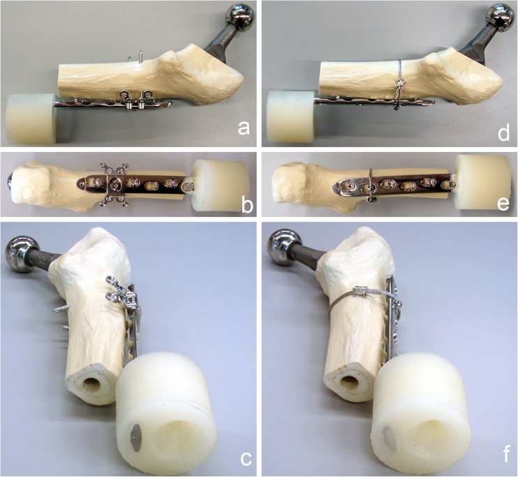
Implantation of the uncemented CBC hip prosthesis (size 9L; Mathys, Bettlach, Switzerland) was done according to the manufacturer’s instructions. A 90° transverse osteotomy was set 5 mm distally to the tip of the prosthesis, simulating a Vancouver type B1 fracture. To focus on the proximal plate fixation and to simulate an unstable fracture situation, only the proximal part of the artificial femur was used. The LCP was previously cut between the eighth and ninth hole, counted from proximal (Fig. 1).
Fig. 1.
Instrumented synthetic femur prepared for testing, cut distally to the tip of the prosthesis stem. The distal end of the locking compression plate (LCP) was potted into PMMA to test only the proximal fixation. a–c Fixation with locking attachment plate (LAP) and unicortical screws. d–f Fixation with cerclage and unicortical screws
The LCP was placed on the lateral aspect of the femur with the centre of the sixth proximal hole over the osteotomy. The long bone axis was aligned in parallel to the LCP axis. Plastic spacers of 2 mm thickness were placed between the LCP and the femur during instrumentation for periosteal and soft tissue simulation. The holes were overdrilled with a Ø 4.7-mm drill instead of Ø 4.3 mm to weaken the screw purchase in the bone, simulating screw fixation in osteoporotic bone. In the first and third hole counted from proximal, 18-mm unicortical periprosthetic Ø 5.0 mm locking screws were placed. A 14-mm unicortical periprosthetic Ø 5.0 mm locking screw was chosen for the fifth hole. Torque was limited at 4 Nm by a torque limiter for all periprosthetic screws. In the cerclage group a Ø 1.7 mm cerclage cable was bonded through an eyelet button at the second LCP hole applying a tensile force of 50 kg before crimp closure (CerclageFix, Synthes, Solothurn, Switzerland). In the LAP group, the LAP was fixed with a connection screw in the second hole of the LCP plate, counted from proximal. The LAP locking screw holes were overdrilled with a Ø 3.1 mm drill instead of Ø 2.8 mm. StarDrive 42 mm and 48 mm bicortical Ø 3.5 mm locking screws were inserted in the first distal anterior and first proximal posterior hole of the LAP, counted from the connection screw. Torque was limited at 1.5 Nm by a torque limiter.
The distal end of the LCP was embedded in polymethylmethacrylate (PMMA) (SCS Beracryl®; W. Troller Kunststoffe AG, Jegenstorf, Switzerland) up to 5 mm distally to the end of the femur, at a distance of 210 mm, measured from the center of the prosthesis head to the distal end of the PMMA. All exposed implant surfaces were covered with plasticine prior to embedding to prevent direct contact with the PMMA.
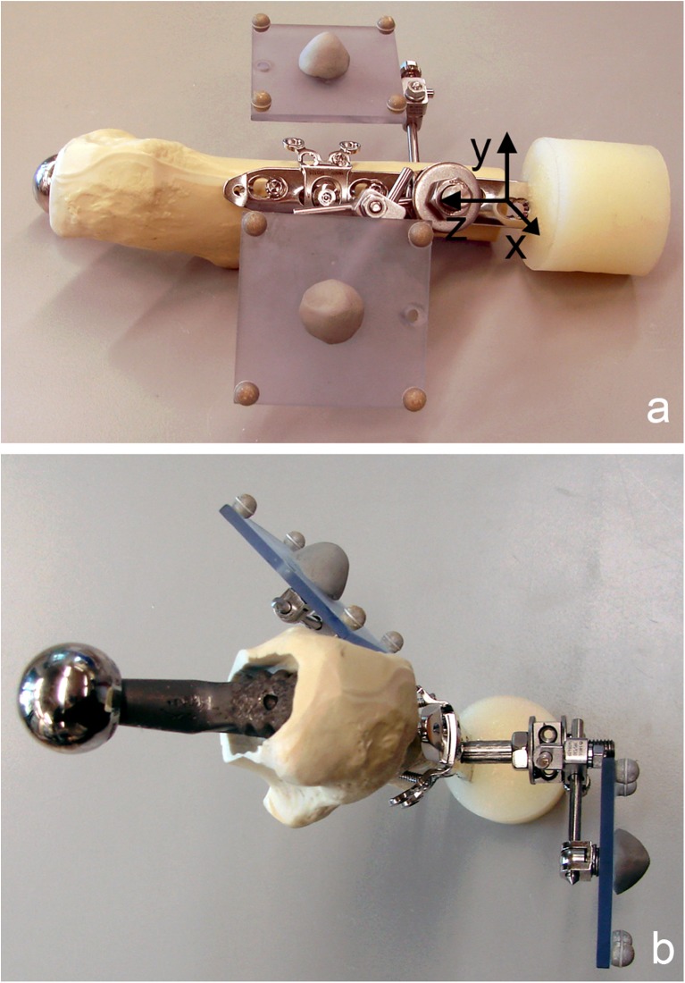
Two marker sets with four retro-reflective markers each were installed. One marker set was mounted on the fourth LCP hole and aligned in parallel to the LCP axis and the sagittal plain of the construct, while the other one was attached to the femur (Fig. 2).
Fig. 2.
Specimen prepared for mechanical testing with two retro-reflective marker sets, consisting of four markers each, attached to the locking compression plate (LCP) (reference marker set) and to the synthetic proximal femur (a lateral view with schematic coordinate system for motion tracking; b cranial view). The reference marker set with markers aligned parallel to the LCP axis and the sagittal plane defines a Cartesian coordinate system (a) with centre on the lateral aspect of the femur on the level of the fourth LCP hole, and the z-axis pointing in the proximal direction along the central axis of the plate and the y-axis anteriorly in the plane of the plate
Mechanical testing
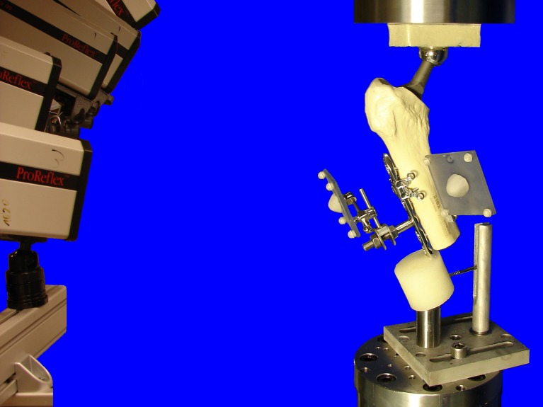
Mechanical testing was performed on a servohydraulic mechanical test system (Mini Bionix 858; MTS Systems, Eden Prairie, USA) with a 4kN/20 Nm load cell. The specimens were attached to the test frame proximally and distally via a ball-and-socket-joint. The distal joint was fixed in the coronal plane to prevent rotation of the entire specimen during testing. The weight bearing axis was orientated from the centre of rotation of the hip joint (head of the prosthesis) to the centre of the distal end of the PMMA pot creating a valgus position of the bone, ensuring a physiological load bearing of the construct with axial compression force as the main load (Fig. 3). According to the model of Duda et al. [13], considering muscle activity for calculation of internal femoral forces and moments, axial compression is the main loading mode within the femoral shaft cortex during a gait cycle, while torsional moments are relatively low and constant along the femoral shaft. Pure bending moments of the femoral shaft, alternating in direction, are only minimal. Therefore the load axis of the specimens was orientated as described above. This position furthermore simulates a one-legged-stand [7], which is generally accepted as worst case scenario for hip joint loading.
Fig. 3.
Test setup with a specimen, mounted on the testing machine in a 20° valgus position ensuring physiological weight bearing and avoiding distal bending moment of the locking compression plate (LCP). The head of the prosthesis was used as a ball-and-socket joint, connecting the specimen to the actuator. Distally the specimen was connected to the load cell via a ball-and-socket-joint. A Schanz-screw in the PMMA block prevented rotational instability around the load axis of the specimens. Cameras on the left recorded the movements of the retroflective marker sets attached to the constructs
At the beginning and after 5000 cycles specimens were loaded with a quasi-static ramp from 50 N to 200 N at a rate of 15 N/s. The cyclic mechanical test was performed at a rate of 3 Hz with sinusoidal axial loading at a constant amplitude of 1800 N during the first 5000 cycles, keeping the axial cyclic loading forces in a range from 200 N (valley) to 2000 N (peak). After 5000 cycles, starting from 2000 N, the peak level was monotonically increased at a rate of 60mN/cycle, until total construct failure occurred. The principle of cyclic testing with monotonically increasing load levels has proven to be useful in previous studies [14].
Data acquisition and analysis
Axial load and axial displacement were recorded from the machine’s transducers at a sampling rate of 128 Hz. At the beginning of the test and after 5000 cycles, construct stiffness was calculated from the load–displacement curve of the quasi-static ramp.
Relative plate-femur interface movements were acquired optically in six degrees of freedom, with use of 3D motion tracking, monitoring the specimen marker sets with five digital cameras (ProReflex MCU; Qualisys AB, Gothenburg, Sweden) at a rate of 100 Hz. Both, optical and machine data were captured simultaneously. Using the optical data, medial bending, anteroposterior bending and axial translation were calculated as functions over time. For this purpose, a custom-made software (Matlab R2010a; The Mathworks, Natick, MA) was used to define a Cartesian coordinate system linked to the plate with the following features: Center at the fourth LCP hole on the lateral aspect of the femur at the level of the osteotomy gap; z-axis in proximal direction along the central axis of the plate; y-axis in the anterior direction, oriented perpendicular to the z-axis in the plane of the plate (Fig. 2) [15].
Peak values of the output variables in loading condition at the beginning of the cyclic test (cycle 1), cycle 500 and cycle 5000 were taken into account for statistical evaluation together with the construct stiffness at the beginning of the test and after 5000 cycles. In addition, an arbitrary criterion for construct failure was defined as 1-mm relative movement in axial translation at the plate–femur interface in loading condition (peak load) and considered together with the type of total construct failure for statistical evaluation as well.
Statistical analysis was performed with the use of SPSS software (IBM SPSS Statistics 19.0, SPSS Inc., Chicago, IL). Post hoc power analysis was calculated by G Power 3.1.3 [16]. The normal distribution within each study group was tested with the Shapiro-Wilk test. The significance of differences between the groups regarding the selected plate–femur interface movements during the cyclic test was tested with general linear model (GLM) repeated measures analysis of variance with a Greenhouse-Geisser epsilon adjustment. Regarding the stiffness, significance of differences between the groups was tested with an unpaired t-test. The significance of differences between the failure modes of both groups was analysed by the chi-square test. Significance level was defined as p = 0.05.
Results
The stiffness of the LAP-construct was significantly higher (p = 0.013, Power1cycle = 0.91, Power5000cycles = 0.99) at the beginning (875.4 N/mm ± 29.8) and after 5000 cycles (1213.0 N/mm ± 101.1) compared to the cerclage-construct with stiffness values of 644.96 N/mm ± 50.1 at the beginning and 851.9 N/mm ± 81.9 after 5000 cycles. Compared to the beginning of the test, the stiffness was significantly higher after 5000 cycles in both groups (p = 0.002).
The relative movements of both groups, translation in axial direction, bending in anteroposterior-direction and bending in medial direction are shown in Table 1. The two groups showed significantly different behaviour regarding the anteroposterior bending (p = 0.02) and axial translation (p = 0.04). Regarding the medial bending, the behaviour of the study groups was not significantly different.
Table 1.
Relative movements of the locking attachment plate (LAP) construct and the cerclage construct (mean and standard deviation [SD]) at the plate-femur interface are given for axial translation, anteroposterior bending and medial bending at the respective time points: beginning (1 cycle) of the test, 500 cycles and 5000 cycles. Differences between the groups, regarding their behaviour during the test were statistically significant for axial translation and anteroposterior (AP) bending
| Measurement | LAP | Cerclage | ||||
|---|---|---|---|---|---|---|
| 1 cycle | 500 cycles | 5000 cycles | 1 cycle | 500 cycles | 5000 cycles | |
| Axial translation (in mm), p = 0.04 | ||||||
| Mean | 0.20 | 0.26 | 0.31 | 0.28 | 0.53 | 0.79 |
| SD | 0.08 | 0.07 | 0.07 | 0.05 | 0.07 | 0.13 |
| Anteroposterior bending (in °), p = 0.02 | ||||||
| Mean | 0.07 | 0.16 | 0.26 | 0.26 | 0.47 | 0.63 |
| SD | 0.02 | 0.10 | 0.11 | 0.04 | 0.03 | 0.18 |
| Medial bending (in °), p = 0.47 | ||||||
| Mean | 1.58 | 2.17 | 2.33 | 2.03 | 2.36 | 2.60 |
| SD | 0.19 | 0.38 | 0.35 | 0.27 | 0.28 | 0.44 |
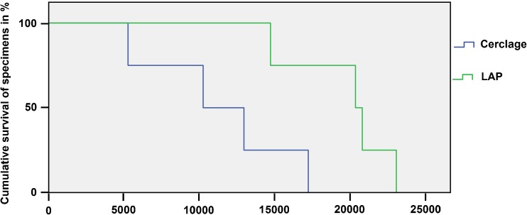
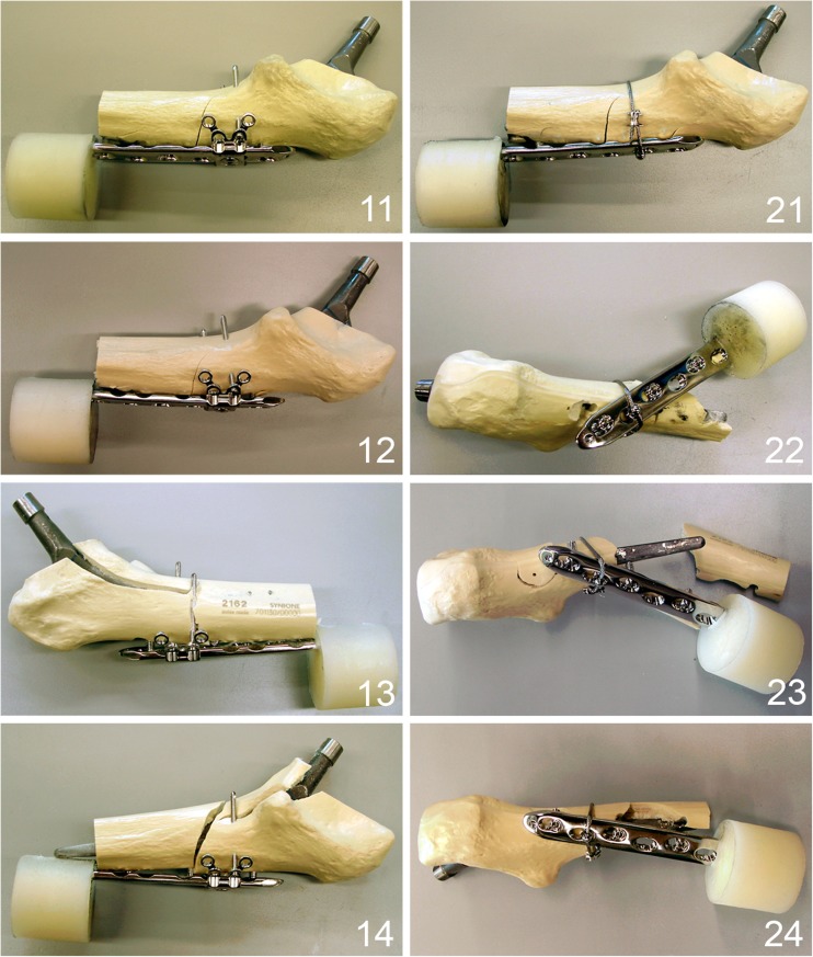
The number of cycles to failure were significantly higher (p = 0.035, power = 0.62) in the LAP group (19519 ± 1758) compared to the cerclage group (11265 ± 2472). The cumulative survival of both constructs is shown in Fig. 4. In general, a loosening between the most distal periprosthetic screw and the bone was at first observed, followed by a crack around the middle periprosthetic screw in all tests and both groups. No distal bending of the LCPs and no failure of the LAP wings were observed in all mechanical tests. Two main types of total failure were observed (Fig. 5)—cracks around all periprosthetic screws without complete plate loosening or breaking of the bone around all periprosthetic screws. Both types of failure resulted from the anteroposterior bending of the construct. In the LAP group only the former type of failure occurred, while in the cerclage group one case with the former type of failure and three cases with the latter type of failure were observed. The mode of failure was significantly different between the groups (p = 0.028).
Fig. 4.
Cumulative survival in both groups upon cycle number. Cumulative survival rate (y-axis) is scaled from 100 % of the specimens intact down to 0 % of the specimens intact where all specimens failed. Failure criterion was defined as a relative movement of 1 mm in axial translation at the plate–femur interface
Fig. 5.
Different failure types of the tested specimens. 11–14 Specimens fixed with locking attachment plate (LAP) plate showing an unique failure mode with cracks around all screws. 21–24 Specimens fixed with cerclage and screws showing a fracturing of the bone around the screws as a result of anteroposterior bending as preponderant failure mode except specimen 21, showing the same failure mode as in the LAP group with cracks around all screws
Discussion
The LAP construct provided an improved mechanical stability and strength, exhibiting generally less relative movements at the plate–femur interface in all registered modalities compared to the cerclage construct. The relative movement is one criterion for fixation stability. A successive increase of relative movements over the time during cyclic testing was observed in both study groups, indicating a loss of stability. This was similarly observed in other studies on periprosthetic fracture fixation including a cyclic testing protocol [8, 17], revealing the importance of cyclic loading to predict biomechanical long-term behaviour of the constructs. Comparing the number of cycles to failure of both groups, a result with statistical significance, but moderate statistical power was achieved, which might be attributed to the low sample number of four specimens per group. However, a statement on the improved mechanical stability of the LAP construct can be given, being supported by the high statistical power comparing the significantly different stiffness values of both groups, which represent the quasi-static part of the test. We observed higher stiffness values in both groups after 5000 cycles compared to the beginning of the cyclic test. We attributed this phenomenon to the settling effect at the endoprosthesis–bone interface since stiffness was determined for the entire construct including the endoprosthesis [18, 19]. Statistical differences between the study groups were not significant for medial bending, where the cerclage exhibits its maximal stability.
This study focussed on the comparison of two different fixation techniques in a standardized test setup, therefore the influence of bone quality on the test results was excluded by the use of synthetic bone. Osteoporotic bone was simulated by over-drilling the screw holes, potentially weakening the LAP construct more than the cerclage construct. However, the stability in the LAP group was comparable to the cerclage group for medial bending and higher for anteroposterior bending and axial translation, which are weak points of the cerclage. The enhanced stability of the LAP construct in the axial direction is important in situations with reduced cortical support like comminuted fractures, where the implant acts as load carrier. Combining the lateral plate osteosynthesis with an allograft placed on the anterior femoral cortex improved medial bending resistance [20]. The enhanced holding strength of this configuration is mainly due to the construct geometry providing a three-dimensional stability. The proximal pullout failure of unicortically fixed locking plates [11] can be explained by the missing offset of the unicortical locking screws in the anteroposterior direction with lacking stability in the sagittal plane. By the lateral positioning of the screws via the LAP, a multidirectional stability could be achieved resulting in a failure mode with cracks around all periprosthetic screws but without complete plate loosening.
Bicortical screw positioning laterally to the prosthesis stem is also provided in a restricted manner by the less invasive stabilization system (LISS), used as “contralateral reversed LISS” (off label use). In their three-year follow-up Kobbe et al. reported on a complication rate of 10 %, namely, two implant failures in a series of 21 patients with periprosthetic femur fractures Vancouver types B and C, treated with LISS plate [21]. Kääb et al. published a series of 11 periprosthetic hip fractures stabilized with LISS plate observing one implant failure and two malunions [22]. No clinical series of LAP application have been published yet.
Conclusion
Allowing bicortical locking screw placement laterally to the prosthesis stem, the LAP is an option to improve stability in periprosthetic fracture fixation.
Acknowledgments
Conflict of interest
The authors are not compensated and there are no other institutional subsidies, corporate affiliations, or funding sources supporting this work unless clearly documented and disclosed. Implants were kindly donated by Synthes GmbH, Solothurn, Switzerland.
Footnotes
This work was performed at the AO Research Institute Davos, Switzerland.
Contributor Information
Mark Lenz, Phone: +41-81-4142211, FAX: +41-81-4142288, Email: mark.lenz@aofoundation.org.
Markus Windolf, Email: markus.windolf@aofoundation.org.
Thomas Mückley, Email: thomas.mueckley@med.uni-jena.de.
Gunther O. Hofmann, Email: gunther.hofmann@med.uni-jena.de
Michael Wagner, Email: michael.wagner@wienkav.at.
Robert G. Richards, Email: geoff.richards@aofoundation.org
Karsten Schwieger, Email: karsten.schwieger@aofoundation.org.
Boyko Gueorguiev, Email: boyko.gueorguiev@aofoundation.org.
References
- 1.Duncan CP, Masri BA. Fractures of the femur after hip replacement. Instr Course Lect. 1995;44:293–304. [PubMed] [Google Scholar]
- 2.Lindahl H, Garellick G, Regner H, Herberts P, Malchau H. Three hundred and twenty-one periprosthetic femoral fractures. J Bone Joint Surg Am. 2006;88:1215–1222. doi: 10.2106/JBJS.E.00457. [DOI] [PubMed] [Google Scholar]
- 3.Pike J, Davidson D, Garbuz D, Duncan CP, O’Brien PJ, Masri BA. Principles of treatment for periprosthetic femoral shaft fractures around well-fixed total hip arthroplasty. J Am Acad Orthop Surg. 2009;17:677–688. doi: 10.5435/00124635-200911000-00002. [DOI] [PubMed] [Google Scholar]
- 4.Ricci WM, Bolhofner BR, Loftus T, Cox C, Mitchell S, Borrelli J., Jr Indirect reduction and plate fixation, without grafting, for periprosthetic femoral shaft fractures about a stable intramedullary implant. J Bone Joint Surg Am. 2005;87:2240–2245. doi: 10.2106/JBJS.D.01911. [DOI] [PubMed] [Google Scholar]
- 5.Virolainen P, Mokka J, Seppanen M, Makela K. Up to 10 years follow up of the use of 71 cortical allografts (strut-grafts) for the treatment of periprosthetic fractures. Scand J Surg. 2010;99:240–243. doi: 10.1177/145749691009900412. [DOI] [PubMed] [Google Scholar]
- 6.Kamineni S, Ware HE. The Mennen plate: unsuitable for elderly femoral peri-prosthetic fractures. Injury. 1999;30:257–260. doi: 10.1016/S0020-1383(99)00076-5. [DOI] [PubMed] [Google Scholar]
- 7.Dennis MG, Simon JA, Kummer FJ, Koval KJ, DiCesare PE. Fixation of periprosthetic femoral shaft fractures occurring at the tip of the stem: a biomechanical study of 5 techniques. J Arthroplast. 2000;15:523–528. doi: 10.1054/arth.2000.4339. [DOI] [PubMed] [Google Scholar]
- 8.Fulkerson E, Koval K, Preston CF, Iesaka K, Kummer FJ, Egol KA. Fixation of periprosthetic femoral shaft fractures associated with cemented femoral stems: a biomechanical comparison of locked plating and conventional cable plates. J Orthop Trauma. 2006;20:89–93. doi: 10.1097/01.bot.0000199119.38359.96. [DOI] [PubMed] [Google Scholar]
- 9.Lever JP, Zdero R, Nousiainen MT, Waddell JP, Schemitsch EH. The biomechanical analysis of three plating fixation systems for periprosthetic femoral fracture near the tip of a total hip arthroplasty. J Orthop Surg Res. 2010;5:45. doi: 10.1186/1749-799X-5-45. [DOI] [PMC free article] [PubMed] [Google Scholar]
- 10.Schmotzer H, Tchejeyan GH, Dall DM. Surgical management of intra- and postoperative fractures of the femur about the tip of the stem in total hip arthroplasty. J Arthroplast. 1996;11:709–717. doi: 10.1016/S0883-5403(96)80010-6. [DOI] [PubMed] [Google Scholar]
- 11.Zdero R, Walker R, Waddell JP, Schemitsch EH. Biomechanical evaluation of periprosthetic femoral fracture fixation. J Bone Joint Surg Am. 2008;90:1068–1077. doi: 10.2106/JBJS.F.01561. [DOI] [PubMed] [Google Scholar]
- 12.Konstantinidis L, Hauschild O, Beckmann NA, Hirschmuller A, Sudkamp NP, Helwig P. Treatment of periprosthetic femoral fractures with two different minimal invasive angle-stable plates: biomechanical comparison studies on cadaveric bones. Injury. 2010;41:1256–1261. doi: 10.1016/j.injury.2010.05.007. [DOI] [PubMed] [Google Scholar]
- 13.Duda GN, Schneider E, Chao EY. Internal forces and moments in the femur during walking. J Biomech. 1997;30:933–941. doi: 10.1016/S0021-9290(97)00057-2. [DOI] [PubMed] [Google Scholar]
- 14.Windolf M, Muths R, Braunstein V, Gueorguiev B, Hanni M, Schwieger K. Quantification of cancellous bone-compaction due to DHS Blade insertion and influence upon cut-out resistance. Clin Biomech (Bristol, Avon) 2009;24:53–58. doi: 10.1016/j.clinbiomech.2008.09.005. [DOI] [PubMed] [Google Scholar]
- 15.Gueorguiev B, Wahnert D, Albrecht D, Ockert B, Windolf M, Schwieger K. Effect on dynamic mechanical stability and interfragmentary movement of angle-stable locking of intramedullary nails in unstable distal tibia fractures: a biomechanical study. J Trauma. 2010;70:358–365. doi: 10.1097/TA.0b013e3181dbaaaf. [DOI] [PubMed] [Google Scholar]
- 16.Faul F, Erdfelder E, Lang AG, Buchner A. G*Power 3: a flexible statistical power analysis program for the social, behavioral, and biomedical sciences. Behav Res Methods. 2007;39:175–191. doi: 10.3758/BF03193146. [DOI] [PubMed] [Google Scholar]
- 17.Dennis MG, Simon JA, Kummer FJ, Koval KJ, Cesare PE. Fixation of periprosthetic femoral shaft fractures: a biomechanical comparison of two techniques. J Orthop Trauma. 2001;15:177–180. doi: 10.1097/00005131-200103000-00005. [DOI] [PubMed] [Google Scholar]
- 18.Kligman M, Rotem A, Roffman M. Cancellous and cortical morselized allograft in revision total hip replacement: a biomechanical study of implant stability. J Biomech. 2003;36:797–802. doi: 10.1016/S0021-9290(03)00013-7. [DOI] [PubMed] [Google Scholar]
- 19.McConnell A, Zdero R, Syed K, Peskun C, Schemitsch E. The biomechanics of ipsilateral intertrochanteric and femoral shaft fractures: a comparison of 5 fracture fixation techniques. J Orthop Trauma. 2008;22:517–524. doi: 10.1097/BOT.0b013e31817d97bc. [DOI] [PubMed] [Google Scholar]
- 20.Talbot M, Zdero R, Schemitsch EH. Cyclic loading of periprosthetic fracture fixation constructs. J Trauma. 2008;64:1308–1312. doi: 10.1097/TA.0b013e31811ea244. [DOI] [PubMed] [Google Scholar]
- 21.Kobbe P, Klemm R, Reilmann H, Hockertz TJ. Less invasive stabilisation system (LISS) for the treatment of periprosthetic femoral fractures: a 3-year follow-up. Injury. 2008;39:472–479. doi: 10.1016/j.injury.2007.10.034. [DOI] [PubMed] [Google Scholar]
- 22.Kaab MJ, Stockle U, Schutz M, Stefansky J, Perka C, Haas NP. Stabilisation of periprosthetic fractures with angular stable internal fixation: a report of 13 cases. Arch Orthop Trauma Surg. 2006;126:105–110. doi: 10.1007/s00402-005-0075-4. [DOI] [PubMed] [Google Scholar]


