Abstract
Evaluation of the loads on the lumbar intervertebral discs is critically important since it is closely related to spine biomechanics, pathology and prosthesis design. Non-invasive estimation of the loads in the discs remains a challenge. In this study we proposed a new technique to estimate in-vivo loads in the IVD using a subject-specific finite element model of the disc and the kinematics of the disc endplates as input boundary conditions. The technique was validated by comparing the forces and moments in the discs calculated from the FE analyses to the in-vitro experiment measurements of three corresponding lumbar discs. The results showed that the forces and moments could be estimated within an average error of 20%. Therefore, this technique can be a promising tool for non-invasive estimation of the loads in the discs and may be extended to be used on living subjects.
Introduction
The pathologies of human lumbar spine are often thought to be related to abnormal biomechanics, such as excessive forces and moments on the lumbar spine during daily activities(Stokes and Iatridis 2004, Mulholland 2008). It is therefore critically important to understand the loading environment in different anatomic structures of the lumbar spine, in order to investigate the disease mechanisms and develop surgical treatment technologies(Pope 1989, Adams et al. 2000). However, determination of the in-vivo spinal loads remains a challenge in biomedical engineering due to the complexity of the spinal geometry, limitations in experimental technologies, as well as the accompanied risks in in-vivo measurements(Nachemson 1981, Wilke et al. 1999, Rohlmann et al. 2000, Polga et al. 2004).
Alternatively, numerous numerical models of the spine have been developed and simulated the spine biomechanics, various spinal injuries and surgical treatment methods(Shirazi-Adl et al. 1984, Gilbertson et al. 1995, Goel and Gilbertson 1995, Natarajan and Andersson 1999, Natarajan et al. 2006, Schmidt et al. 2007, Zander et al. 2009, Schmidt et al. 2010). In most of the numerical models, external loadings were usually applied to the spine to calculate the kinematic responses and the internal forces and moments of different spinal structures. The validity and accuracy of the results largely depend on the simulated external loadings, especially when studying complex functional motions(Adams 1995, Dreischarf et al. 2010). Currently, most studies applied compressive forces and/or pure rotational moments in the three principal planes(Wilke et al. 2001). A few investigations have reported improved finite element (FE) analysis results by using modified external loading conditions that were calculated from the kinematic models of the lumbar spine(Goel et al. 1993, Rohlmann et al. 2001, Renner et al. 2007, Rohlmann et al. 2009a, Arjmand et al. 2011). However, the physiological loading conditions of the lumbar spine, especially during functional activities, are still unclear.
Recently, the authors have developed a non-invasive imaging technique that combines 3 dimensional (3D) CT/MRI modeling and dual fluoroscopic imaging system (DFIS) technique to accurately determine subject-specific in-vivo spine kinematics(Wang et al. 2008) during experiments. In-vivo kinematics of the vertebrae, the intervertebral discs (IVDs), the facet joints and the spinous process of both healthy subjects and patients with spinal diseases have been determined(Kozanek et al. 2009, Li et al. 2009, Wang et al. 2009, Xia et al. 2009, Xia et al. 2010, Li et al. 2011, Passias et al. 2011, Wang et al. 2011). Therefore, instead of using simulated external loadings, it is possible to use the in-vivo spine kinematics as input boundary conditions in the well-established FE models of the lumbar spine to estimate the in-vivo spinal forces and moments.
As a first step, the current study focused on the lumbar IVD, which plays an important role in the lumbar biomechanics and is closely related to most spinal pathologies and injuries. The aim of this study is to demonstrate that it is possible to use subject specific kinematics of the IVD endplates in FE analysis to estimate the forces and moments in the IVD. For this purpose, in-vitro robotic loading experiments were performed on three lumbar IVDs. The kinematics of the IVD endplates during the experiments were determined using the DFIS. FE models of the IVDs were built based on CT scans and existing literature. The forces and moments in the IVDs were calculated from FE analyses using the kinematics as input boundary conditions, and compared to the experimental measurements for validation.
Material and Methods
Specimen Preparation
Three fresh-frozen cadaveric lumbar spinal functional spinal units (FSUs) (two L2/3 and one L4/5, 23 to 44 years old) with healthy IVDs were selected from 3 donors. The FSUs were evaluated using a fluoroscope before the experiments and were dissected after the experiments to check for any abnormality in the IVDs. Each FSU was thawed and carefully dissected to remove the soft tissues and posterior elements in order to focus only on the force-displacement behavior of the IVD. The vertebral bodies were then potted in bone cement for fixation onto the testing system. In addition, 8 titanium beads were implanted on the bone cement. The specimen was then CT scanned with slice thickness of 0.6 mm (LightSpeed Pro16, GE, Waukesha, WI).
In-vitro Testing Protocol
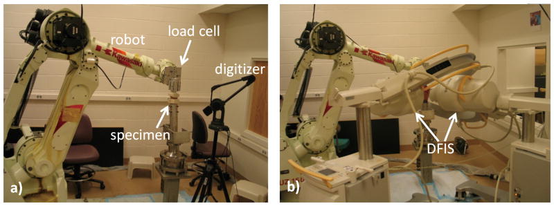
To study the force-displacement behavior of the IVDs, we used a 6 DOF robotic testing system (Kawasaki UZ150, Kawasaki Heavy Industry, Japan) (Fig 1a). Its operation has been detailed in previous studies(Li et al. 2002). Briefly, each IVD was tested under 7 loading cases: a 400N compression, 5Nm flexion/extension, left/right lateral bendings and left/right torsions. The center of the disc and the principal directions were determined using a 3D digitization platform (MicroScribe 3DX Digitizer, Immersion Corporation, San Jose, CA) and recorded in a coordinate system. The titanium beads implanted on the bone cement were also digitized and used as reference points so that the same coordinate system can be registered with the FE models.
Fig 1.
Experiment setup a) Installation of the lumbar MSU on the 6DOF robotic system. b) Capturing fluoroscopic images of the MSU using DFIS.
During the experiments, the inferior endplate of each IVD was fixed and the superior endplate was free for movement by the robot. The robotic system determined the optimized loading path for each loading case(Li, et al. 2002), from 0 to 100% of the magnitude of the target loading (400N or 5Nm) in 10% increments. An optimized loading path is described as the positions of the specimen where the resultant force in the tested 1 DOF was within the error (<10 N or <0.3Nm) of its 10% increment step, and the resultant forces and moments in all other 5 DOFs were minimal (<10 N and <0.3Nm, respectively). In other words, in each loading case the specimen was loaded in only 1 DOF while the forces and moments along the other coupled 5 DOFs were minimized to zero. During each loading case, fluoroscopic images of the specimens were captured using the DFIS (Fig 1b). At the same time, forces and moments were recorded by the load cell (JR3 DSP-based force sensor receiver, JR3 Inc., Woodland, CA) attached to the robotic system and transferred to the center of the disc using a custom Matlab code (Matlab 2010a, MathWorks Inc., Natick, MA). During each loading case, the robot moving speed was set to be similar to the normal moving speed of human lumbar spine. Between each loading case, the discs were kept still for 30 minutes at the neutral position to minimize any residue forces and moments due to the viscoelastic behavior.
Determination of the Kinematics of the Disc Endplates
For each specimen, 3D geometric models were reconstructed from the CT images. The positions of the vertebrae during the loading history on the robot were then reproduced in a commercial solid modeling software (Rhinoceros, Robert McNeel & Associates, Seattle, WA), where the projections of the 3D CT models were matched to their 2D osseous contours on the fluoroscopic images obtained in the robot experiments (Fig 2). This technique has been extensively used in our previous kinematic studies of the lumbar spine(Kozanek, et al. 2009, Li, et al. 2009, Wang, et al. 2009, Xia, et al. 2009, Xia, et al. 2010, Li, et al. 2011, Passias, et al. 2011, Wang, et al. 2011) and has been validated to have an accuracy within 0.3 mm in translation and 0.7° in rotation(Wang, et al. 2008, Li, et al. 2009). Similarly, the positions of the implanted titanium beads were reproduced using the DFIS (Fig 3). Since the relationship between the locations of the titanium beads and the coordinate system were recorded during the experiment using the digitizer, the same center of the disc and principal directions can be determined and registered with the 3D model (Fig 3). The relative motion of the superior endplate with respect to the inferior endplate were determined from the vertebral kinematics, and described in the coordinate system using Euler angles in the flexion-bending-torsion order. Therefore, both the geometric details of the IVD endplates and their kinematics during each loading case were obtained for the FE modeling of the IVDs.
Fig 2.
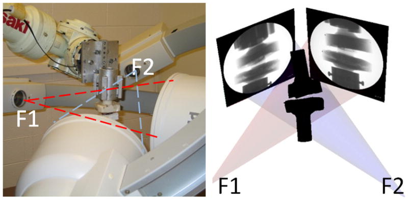
Reproduction of the positions of the vertebrae using an established image matching protocol.
Fig 3.
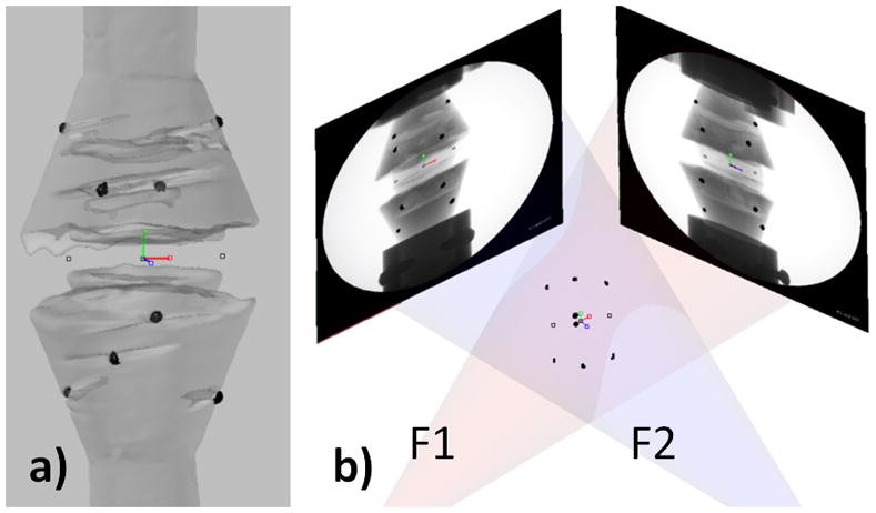
Registration of the coordinate system a) Determination of the coordinate system for the IVD center and the principal directions. Recording the relative position of the coordinate system and several titanium beads using a digitizer. b) Registering the coordinate system with the FEA model by matching the titanium beads.
Finite Element Models of the IVDs
A custom Matlab code was used to create subject geometric-specific FE models with hexahedral elements from the 3D CT models (Fig 4). In this study, the vertebral bodies were assumed to be rigid, thus only FE models of the IVDs were built. Each IVD was modeled into four parts: nucleus pulposus (NP), annulus ground substance (GS), eight layers of annulus fibrosi (AFs), and two endplates. Material properties were taken from literature (Table 1)(Shirazi-Adl, et al. 1984, Goel, Monroe, et al. 1995, Smit et al. 1997, Polikeit et al. 2003, Rohlmann et al. 2005, Rohlmann et al. 2006, Rohlmann et al. 2009b). NP was estimated to occupy 40% volume of the whole disc and modeled as hydraulic fluid(Rohlmann, et al. 2005, Rohlmann, et al. 2006, Rohlmann, et al. 2009b). The volumetric center of the NP was chosen as a reference node of the NP fluid and the initial pressure was set as 0. GS was divided into eight layers and was modeled as hyper-elastic solid. Eight layers of AFs were inserted onto the outer surface and between each two layers of GS. Based on the anatomy, the angles between AFs and disc endplates were set to be 30° and 150° (Shirazi-Adl, et al. 1984, Goel, et al. 1995, Smit, et al. 1997, Polikeit, et al. 2003). Physiological cross sectional area of AFs was calculated to take up to 16% volume of each annulus layer(Shirazi-Adl, et al. 1984, Goel, et al. 1995, Smit, et al. 1997, Polikeit, et al. 2003). AFs were modeled as tension only truss element with gradually changing stiffness for each layer. Inferior and superior endplates were modeled as rigid plates. There were totally about 10,000 elements and 4,000 nodes in each IVD model.
Fig 4.
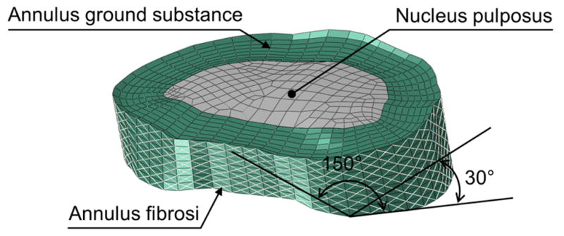
Schematic of the FE model of an IVD
Table 1.
Material properties used in FE models.
| Type of element | Elastic modulus (MPa) | Poisson’s ratio | ||
|---|---|---|---|---|
| Nucleus pulposus* | Hydraulic fluid element | - | - | |
| Annulus ground substance (Annulus bulk)** | Neo-Hookean Hexahedral solid element C10=0.348, D1=0.3 | - | - | |
| Annulus fibrosus*** | Tension only elastic truss element | Layers 1,2 | 550 | 0.3 |
| Layers 3,4 | 495 | 0.3 | ||
| Layers 5,6 | 421.5 | 0.3 | ||
| Layers 7,8 | 357.5 | 0.3 | ||
| Endplates | Rigid shell element | - | - | |
Rohlmann, et al. 2005, Rohlmann, et al. 2006, Rohlmann, et al. 2009b
Rohlmann, et al. 2006
Abaqus Standard/6.10 (Simulia, Providence, RI) was used for FE calculations. For each FE IVD model, the inferior endplate was fixed in all directions and the superior endplate was moved according to the 6DOF kinematics measured by the DFIS during the experiments. Resultant forces and moments were calculated and compared with those measured in the experiment in the same coordinate system for validation.
Results
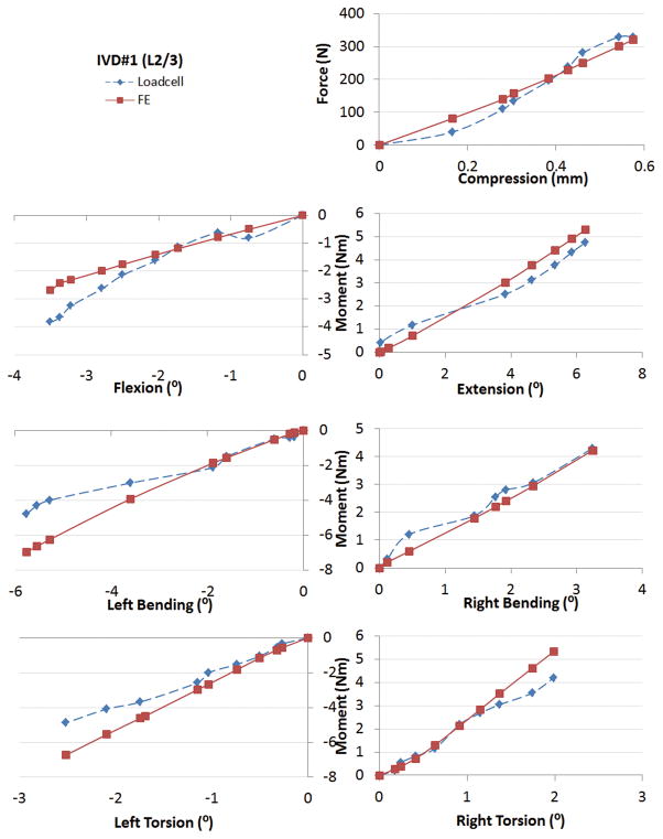
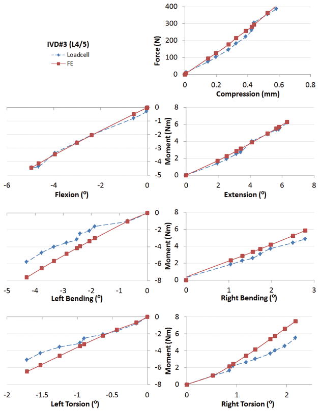
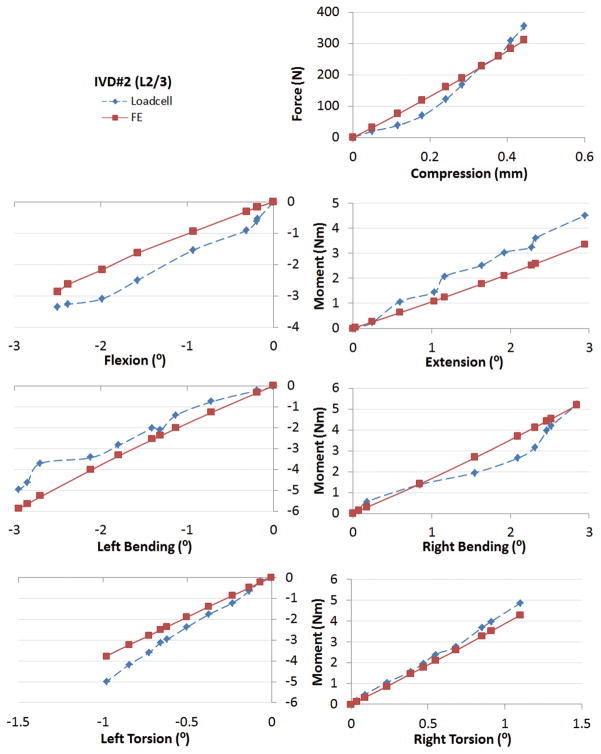
The forces and moments calculated by the subject-specific FE analysis had good agreements with those recorded in the in-vitro experiments in the whole range. Fig 5–7 showed the force-displacement (or moment-rotation) behaviors of the three IVDs under different loading cases. The x axes were the primary translations or rotations (the DOF corresponding to each loading case) of the superior endplates with respect to the inferior endplates, where the rotations were described using Euler angles in the flexion-bending-torsion order. The y axes were the primary forces or moments at the center of the disc. We quantitatively compared: (1) the forces or moments at the end steps of the loading cases, and (2) the overall areas under the force-displacement or moment-rotation curves (which were related to the energy of disc deformation) between FE modeling and in-vitro experiment results. The overall average differences were 18% and 19%, respectively.
Fig 5.
Comparison of the force-displacement curves between FE analyses and experiment measurements under various loading cases for IVD#1.
Fig 7.
Comparison of the force-displacement curves between FE analyses and experiment measurements under various loading cases for IVD#3.
Accuracy in the Primary Loaded DOF
Under 400N compressive loads, the FE analyses had average differences of 6.5% in estimation of the forces at the end steps, and 9.4% in estimation of the overall areas under the force-displacement curves when compared to the robot measurements (Table 2, 3, Fig 5–7). Under 5Nm flexion/extension moments, the FE analyses had average differences of 14.8% and 12.9% in estimation of the moments at the end steps; and 19.1% and 14.2% in estimation of the overall areas under the force-displacement curves for flexion and extension, respectively when compared to the robot measurements (Table 2, 3, Fig 5–7). Under 5Nm left/right lateral bending moments, the FE analysis had average differences of 31.6% and 7.6% in estimation of the moments at the end steps; and 33.5% and 15.9% in estimation of the overall areas under the force-displacement curves for left bending and right bending, respectively when compared to the robot measurements (Table 2, 3, Fig 5–7). Under 5Nm left/right torsion moments, the FE analysis had average differences of 29.8% and 24.9% in estimation of the moments at the end steps; and 23.6% and 20.0% in estimation of the overall areas under the force-displacement curves for left torsion and right torsion, respectively when compared to the robot measurements (Table 2, 3, Fig 5–7).
Table 2.
Errors in estimation of the forces at the end steps of various loadings. Average differences and standard deviations (SDs) were calculated.
| L2/3#1 | L2/3#2 | L4/5 | Average | |
|---|---|---|---|---|
| Comp | 2.1% | 12.4% | 4.8% | 6.5% |
| Flex | 29.5% | 14.4% | 0.5% | 14.8% |
| Ext | 11.5% | 25.9% | 1.3% | 12.9% |
| BendL | 45.4% | 18.1% | 31.3% | 31.6% |
| BendR | 1.7% | 0.8% | 20.4% | 7.6% |
| TwistL | 38.0% | 24.6% | 26.8% | 29.8% |
| TWistR | 26.9% | 12.0% | 35.9% | 24.9% |
| Average | 22.0% | 15.5% | 17.3% |
Table 3.
Errors in prediction of the overall areas under the force-displacement curves of various loadings. Average differences and standard deviations (SDs) were calculated.
| L2/3#1 | L2/3#2 | L4/5 | Average | |
|---|---|---|---|---|
| Comp | 7.1% | 12.2% | 8.8% | 9.4% |
| Flex | 19.6% | 33.7% | 3.8% | 19.1% |
| Ext | 7.5% | 29.0% | 6.1% | 14.2% |
| BendL | 30.4% | 28.8% | 41.4% | 33.5% |
| BendR | 10.0% | 17.4% | 20.3% | 15.9% |
| TwistL | 28.7% | 22.2% | 19.9% | 23.6% |
| TwistR | 15.0% | 11.2% | 33.9% | 20.0% |
| Average | 16.7% | 22.1% | 19.2% |
Accuracy in the Coupled 5 DOF
During the experiment, the robot measurements of the forces and moments in the 5 DOF other than the loaded DOF were almost zero due to the experiment setup. The FE analyses yielded good agreements with the experiment results. Forces and moments were consistently less than 50N and 1Nm, respectively, in the 5 DOF other than the tested DOF in each loading case.
Discussion
Accurate determination of the loads on the lumbar spine presents a challenge in biomedical engineering. In this study, we validated that the forces and moments of the IVDs can be estimated using subject-specific 3D FE IVD models and the kinematics of the same IVD measured during functional activities. The data indicated that the forces and moments in the IVDs could be estimated within an average error of 20% of the actual loads.
In literature, most validations of the FE models were performed by comparing various kinematic responses of the lumbar spine of the FE calculation to those obtained from multiple in-vitro experiments under controlled external loadings(Shirazi-Adl, et al. 1984, Goel, et al. 1993, Goel and Gilbertson 1995, Natarajan and Andersson 1999, Zander et al. 2001, Schmidt, et al. 2007). Because of the high variability inherent to experimentation, an FE model is commonly considered valid when its predicted result is within the standard deviation of several experiment results and quantitative results may not be reported. Shirazi-Adl et al.(Shirazi-Adl, et al. 1984) validated an FE model by comparing the model estimations to the in-vitro experiment results in terms of axial displacement, disc bulge, end-plate bulge and intradiscal pressure under several external loadings. Natarajan et al.(Natarajan and Andersson 1999) validated an FE model by comparing the model estimations to the in-vitro experiment results in terms of axial displacement and segmental rotations. Goel et al.(Goel, et al. 1993) validated an FE model by comparing the model estimations to the in-vitro experiment results in terms of the axial displacement, segmental rotations, and intradiscal pressure under external loadings. Rohlmann et al.(Zander, et al. 2001, Rohlmann, et al. 2006) validated an FE model by comparing the model estimations to the in-vitro experiment results in terms of axial displacement, segmental rotations, and intradiscal pressure. These FE models have then played important roles to investigate spine biomechanics under various simulated loading conditions(Shirazi-Adl, et al. 1984, Gilbertson, et al. 1995, Goel and Gilbertson 1995, Natarajan and Andersson 1999, Natarajan, et al. 2006, Schmidt, et al. 2007, Kozanek, et al. 2009, Li, et al. 2009, Wang, et al. 2009, Xia, et al. 2009, Zander, et al. 2009, Schmidt, et al. 2010, Xia, et al. 2010, Li, et al. 2011, Passias, et al. 2011, Wang, et al. 2011).
In this validation study, instead of validating the kinematic responses, we validated the force responses of the FE models by directly comparing those with the in-vitro experiment results of the same IVDs using kinematics as input boundary conditions. It is not a conventional approach, since the force responses are very sensitive with respect to the kinematic inputs, which cannot be measured accurately enough previously. It is made possible by taking advantage of some recently developed imaging techniques, such as DFIS(Wang, et al. 2008), where all 6DOF translations and rotations can be accurately determined to certain extent. Further technological development in imaging techniques such as better image resolution and contrast can possibly improve the accuracy of the proposed technique.
There are only few previous techniques measured the in-vivo spinal forces(Nachemson 1981, Wilke, et al. 1999, Rohlmann, et al. 2000, Polga, et al. 2004), mainly because that direct measurements can be invasive and highly risky. Pressure transducers have been used to measure intradiscal pressure during sitting, standing and other daily activities to provide information for physiotherapy, rehabilitation programs and workplace recommendations(Nachemson 1981, Wilke, et al. 1999). Rohlmann et al.(Rohlmann, et al. 2000) used a telemeterized internal spinal fixation device to measure the forces in spinal implants and investigated load sharing after fusion. The combined numerical and experimental technique validated in this paper could provide an alternative way to estimate the in-vivo spinal forces non-invasively. Similar to this validation study, 3D subject-specific FE vertebral models can be generated from the subject-specific CT/MRI geometric models. In-vivo vertebral kinematics can be measured using the combined CT/MRI and DFIS technique(Wang, et al. 2008, Li, et al. 2009) during experiments when subjects perform different activities. The vertebral kinematics can then be input into the corresponding 3D FE IVD models as boundary conditions to calculate the in-vivo forces and moments on the IVD.
Although the FE results showed overall good agreement with the experiment measurements in the whole range, we observed a couple relatively high percentage errors, especially during bending left (Table 2, 3). It is partially because the FE models were stiffer during bending, resulting large percentage errors when using experiment measurements as basis, but not necessary large absolute errors. Similarly, in the literature most FE validation studies could not have perfect matches under all loading conditions. Describing the IVD material behavior is a still ongoing task, which has been tried for decades. The properties of the discs underlie a larger variability in literature, as well as intra- and inter- subject variation. In the future, it should be interesting to test more IVDs and run a probabilistic design analysis to find the optimization material properties.
Since the kinematics of the disc endplates were used as input boundary conditions, only IVDs were necessary in the FE models. It greatly simplified the calculation and reduced the time and effort to determine the geometries, characterize the material properties and analyze the force interactions of the different structures of the lumbar spine. It also helps to explain why the force-displacement (or moment-rotation) curves showed less non-linearity in both the experiments and the FE analyses compared to existing literature. In our validation, the force-displacement curves only represented the response of the IVDs without taking the highly non-linear spinal ligaments into account.
As any other finite element analyses, there are a series of factors that may affect the accuracy of the estimations of in-vivo spinal forces using our FE modeling technique. Certain assumptions and simplifications have been made in our study in the FE modeling and in-vitro experiments. For instance, the vertebrae were considered as rigid bodies in the FE models. However, the bone compliance may play a role in spine biomechanics as indicated by Shirazi-Adl et al(Shirazi-Adl 1994) and Goel et al(Goel, Ramirez, et al. 1995). We adopted a common assumption in FE that the nucleus occupies 40% volume of the whole disc (Smit, et al. 1997, Rohlmann, et al. 2006, Rohlmann, et al. 2009b). However, accurate determination of the proportion of NP shall probably decrease the error. In the future we will try to quantitatively determine the volume of NP from MR images. We also did not include cartilage endplate and disc bulging in the FE models. Although there was a 30 minutes resting time between any two loading cases during the experiments to minimize residue forces due to the viscoelastic behavior, viscoelastic behavior of the IVDs(Natarajan, et al. 2006, Rohlmann, et al. 2006) can still play a role during each loading phase but was not included in the FE modeling. There were hysteresis effects and load-deformation curves were slightly different between loading and unloading. In the current study, the ones during loading were taken for comparison with FEA. In addition, the IVD properties may be subject-specific and segment-specific in the in-vivo physiological environment which may require further investigation. With all these limitations, the proposed technique was shown to estimate forces and moments on the lumbar IVDs within an average error of 20%.
Conclusion
We performed a validation study of a technique that uses endplates kinematics as inputs in the FE models to estimate the forces and moments in the human lumbar IVDs. The forces and moments could be estimated within an average error of 20%. Therefore, this technique can be a promising tool for non-invasive estimation of the forces and moments of the IVDs during various functional activities of living subjects, which may benefit the numerical and biomechanical community by providing the baseline data.
Fig 6.
Comparison of the force-displacement curves between FE analyses and experiment measurements under various loading cases for IVD#2.
Acknowledgments
We would like to acknowledge the financial supports from NASS, SRS, NIH (R21AR057989) and NAP (P-09-JC-LU63-C01),
Footnotes
Conflict of interest statement
None
References
- Stokes IA, Iatridis JC. Mechanical conditions that accelerate intervertebral disc degeneration: overload versus immobilization. Spine (Phila Pa 1976) 2004;29(23):2724–2732. doi: 10.1097/01.brs.0000146049.52152.da. Available from http://www.ncbi.nlm.nih.gov/pubmed/15564921 doi 00007632-200412010-00016 [pii] [DOI] [PMC free article] [PubMed] [Google Scholar]
- Mulholland RC. The myth of lumbar instability: the importance of abnormal loading as a cause of low back pain. Eur Spine J. 2008;17(5):619–625. doi: 10.1007/s00586-008-0612-2. Available from http://www.ncbi.nlm.nih.gov/pubmed/18301932 doi 10.1007/s00586-008-0612-2. [DOI] [PMC free article] [PubMed] [Google Scholar]
- Pope MH. Biomechanics of the lumbar spine. Ann Med. 1989;21(5):347–351. doi: 10.3109/07853898909149219. Available from http://www.ncbi.nlm.nih.gov/pubmed/2532524. [DOI] [PubMed] [Google Scholar]
- Adams MA, Freeman BJ, Morrison HP, Nelson IW, Dolan P. Mechanical initiation of intervertebral disc degeneration. Spine (Phila Pa 1976) 2000;25(13):1625–1636. doi: 10.1097/00007632-200007010-00005. Available from http://www.ncbi.nlm.nih.gov/pubmed/10870137. [DOI] [PubMed] [Google Scholar]
- Nachemson AL. Disc pressure measurements. Spine (Phila Pa 1976) 1981;6(1):93–97. doi: 10.1097/00007632-198101000-00020. Available from http://www.ncbi.nlm.nih.gov/pubmed/7209680. [DOI] [PubMed] [Google Scholar]
- Wilke HJ, Neef P, Caimi M, Hoogland T, Claes LE. New in vivo measurements of pressures in the intervertebral disc in daily life. Spine (Phila Pa 1976) 1999;24(8):755–762. doi: 10.1097/00007632-199904150-00005. Available from http://www.ncbi.nlm.nih.gov/pubmed/10222525. [DOI] [PubMed] [Google Scholar]
- Rohlmann A, Graichen F, Weber U, Bergmann G. 2000 Volvo Award winner in biomechanical studies: Monitoring in vivo implant loads with a telemeterized internal spinal fixation device. Spine (Phila Pa 1976) 2000;25(23):2981–2986. doi: 10.1097/00007632-200012010-00004. Available from http://www.ncbi.nlm.nih.gov/pubmed/11145808. [DOI] [PubMed] [Google Scholar]
- Polga DJ, Beaubien BP, Kallemeier PM, Schellhas KP, Lew WD, Buttermann GR, Wood KB. Measurement of in vivo intradiscal pressure in healthy thoracic intervertebral discs. Spine (Phila Pa 1976) 2004;29(12):1320–1324. doi: 10.1097/01.brs.0000127179.13271.78. Available from http://www.ncbi.nlm.nih.gov/pubmed/15187632 doi 00007632-200406150-00009 [pii] [DOI] [PubMed] [Google Scholar]
- Shirazi-Adl SA, Shrivastava SC, Ahmed AM. Stress analysis of the lumbar disc-body unit in compression.. A three-dimensional nonlinear finite element study. Spine (Phila Pa 1976) 1984;9(2):120–134. doi: 10.1097/00007632-198403000-00003. Available from http://www.ncbi.nlm.nih.gov/pubmed/6233710. [DOI] [PubMed] [Google Scholar]
- Gilbertson LG, Goel VK, Kong WZ, Clausen JD. Finite element methods in spine biomechanics research. Crit Rev Biomed Eng. 1995;23(5–6):411–473. doi: 10.1615/critrevbiomedeng.v23.i5-6.20. Available from http://www.ncbi.nlm.nih.gov/pubmed/9017345. [DOI] [PubMed] [Google Scholar]
- Goel VK, Gilbertson LG. Applications of the finite element method to thoracolumbar spinal research--past, present, and future. Spine (Phila Pa 1976) 1995;20(15):1719–1727. Available from http://www.ncbi.nlm.nih.gov/pubmed/7482024. [PubMed] [Google Scholar]
- Natarajan RN, Andersson GB. The influence of lumbar disc height and cross-sectional area on the mechanical response of the disc to physiologic loading. Spine (Phila Pa 1976) 1999;24(18):1873–1881. doi: 10.1097/00007632-199909150-00003. Available from http://www.ncbi.nlm.nih.gov/pubmed/10515010. [DOI] [PubMed] [Google Scholar]
- Natarajan RN, Williams JR, Andersson GB. Modeling changes in intervertebral disc mechanics with degeneration. J Bone Joint Surg Am. 2006;88(Suppl 2):36–40. doi: 10.2106/JBJS.F.00002. Available from http://www.ncbi.nlm.nih.gov/pubmed/16595441 doi 88/1_suppl_2/36 [pii] 10.2106/JBJS.F.00002. [DOI] [PubMed] [Google Scholar]
- Schmidt H, Heuer F, Drumm J, Klezl Z, Claes L, Wilke HJ. Application of a calibration method provides more realistic results for a finite element model of a lumbar spinal segment. Clin Biomech (Bristol, Avon) 2007;22(4):377–384. doi: 10.1016/j.clinbiomech.2006.11.008. Available from http://www.ncbi.nlm.nih.gov/pubmed/17204355 doi S0268-0033(06)00224-5 [pii] 10.1016/j.clinbiomech.2006.11.008. [DOI] [PubMed] [Google Scholar]
- Zander T, Rohlmann A, Bergmann G. Influence of different artificial disc kinematics on spine biomechanics. Clin Biomech (Bristol, Avon) 2009;24(2):135–142. doi: 10.1016/j.clinbiomech.2008.11.008. Available from http://www.ncbi.nlm.nih.gov/pubmed/19121822 doi S0268-0033(08)00323-9 [pii] 10.1016/j.clinbiomech.2008.11.008. [DOI] [PubMed] [Google Scholar]
- Schmidt H, Shirazi-Adl A, Galbusera F, Wilke HJ. Response analysis of the lumbar spine during regular daily activities--a finite element analysis. J Biomech. 2010;43(10):1849–1856. doi: 10.1016/j.jbiomech.2010.03.035. Available from http://www.ncbi.nlm.nih.gov/pubmed/20394933 doi S0021-9290(10)00180-6 [pii] 10.1016/j.jbiomech.2010.03.035. [DOI] [PubMed] [Google Scholar]
- Adams MA. Mechanical testing of the spine. An appraisal of methodology, results, and conclusions. Spine (Phila Pa 1976) 1995;20(19):2151–2156. doi: 10.1097/00007632-199510000-00015. Available from http://www.ncbi.nlm.nih.gov/pubmed/8588174. [DOI] [PubMed] [Google Scholar]
- Dreischarf M, Zander T, Bergmann G, Rohlmann A. A non-optimized follower load path may cause considerable intervertebral rotations. J Biomech. 2010;43(13):2625–2628. doi: 10.1016/j.jbiomech.2010.05.033. Available from http://www.ncbi.nlm.nih.gov/pubmed/20541208 doi S0021-9290(10)00320-9 [pii] 10.1016/j.jbiomech.2010.05.033. [DOI] [PubMed] [Google Scholar]
- Wilke HJ, Rohlmann A, Neller S, Schultheiss M, Bergmann G, Graichen F, Claes LE. Is it possible to simulate physiologic loading conditions by applying pure moments? A comparison of in vivo and in vitro load components in an internal fixator. Spine (Phila Pa 1976) 2001;26(6):636–642. doi: 10.1097/00007632-200103150-00014. Available from http://www.ncbi.nlm.nih.gov/pubmed/11246374. [DOI] [PubMed] [Google Scholar]
- Goel VK, Kong W, Han JS, Weinstein JN, Gilbertson LG. A combined finite element and optimization investigation of lumbar spine mechanics with and without muscles. Spine (Phila Pa 1976) 1993;18(11):1531–1541. Available from http://www.ncbi.nlm.nih.gov/pubmed/8235826. [PubMed] [Google Scholar]
- Rohlmann A, Neller S, Claes L, Bergmann G, Wilke HJ. Influence of a follower load on intradiscal pressure and intersegmental rotation of the lumbar spine. Spine (Phila Pa 1976) 2001;26(24):E557–561. doi: 10.1097/00007632-200112150-00014. Available from http://www.ncbi.nlm.nih.gov/pubmed/11740371. [DOI] [PubMed] [Google Scholar]
- Renner SM, Natarajan RN, Patwardhan AG, Havey RM, Voronov LI, Guo BY, Andersson GB, An HS. Novel model to analyze the effect of a large compressive follower pre-load on range of motions in a lumbar spine. J Biomech. 2007;40(6):1326–1332. doi: 10.1016/j.jbiomech.2006.05.019. Available from http://www.ncbi.nlm.nih.gov/pubmed/16843473 doi S0021-9290(06)00181-3[pii] 10.1016/j.jbiomech.2006.05.019. [DOI] [PubMed] [Google Scholar]
- Rohlmann A, Zander T, Rao M, Bergmann G. Realistic loading conditions for upper body bending. J Biomech. 2009a;42(7):884–890. doi: 10.1016/j.jbiomech.2009.01.017. Available from http://www.ncbi.nlm.nih.gov/pubmed/19268291 doi S0021-9290(09)00042-6 [pii] 10.1016/j.jbiomech.2009.01.017. [DOI] [PubMed] [Google Scholar]
- Arjmand N, Plamondon A, Shirazi-Adl A, Lariviere C, Parnianpour M. Predictive equations to estimate spinal loads in symmetric lifting tasks. J Biomech. 2011;44(1):84–91. doi: 10.1016/j.jbiomech.2010.08.028. Available from http://www.ncbi.nlm.nih.gov/pubmed/20850750 doi S0021-9290(10)00472-0 [pii] 10.1016/j.jbiomech.2010.08.028. [DOI] [PubMed] [Google Scholar]
- Wang S, Passias P, Li G, Wood K. Measurement of vertebral kinematics using noninvasive image matching method-validation and application. Spine (Phila Pa 1976) 2008;33(11):E355–361. doi: 10.1097/BRS.0b013e3181715295. Available from http://www.ncbi.nlm.nih.gov/pubmed/18469683 doi 10.1097/BRS.0b013e318171529500007632-200805150-00024 [pii] [DOI] [PubMed] [Google Scholar]
- Kozanek M, Wang S, Passias PG, Xia Q, Li G, Bono CM, Wood KB. Range of motion and orientation of the lumbar facet joints in vivo. Spine (Phila Pa 1976) 2009;34(19):E689–696. doi: 10.1097/BRS.0b013e3181ab4456. Available from http://www.ncbi.nlm.nih.gov/pubmed/19730201 doi 10.1097/BRS.0b013e3181ab445600007632-200909010-00004 [pii] [DOI] [PubMed] [Google Scholar]
- Li G, Wang S, Passias P, Xia Q, Wood K. Segmental in vivo vertebral motion during functional human lumbar spine activities. Eur Spine J. 2009;18(7):1013–1021. doi: 10.1007/s00586-009-0936-6. Available from http://www.ncbi.nlm.nih.gov/pubmed/19301040 doi 10.1007/s00586-009-0936-6. [DOI] [PMC free article] [PubMed] [Google Scholar]
- Wang S, Xia Q, Passias P, Wood K, Li G. Measurement of geometric deformation of lumbar intervertebral discs under in-vivo weightbearing condition. J Biomech. 2009;42(6):705–711. doi: 10.1016/j.jbiomech.2009.01.004. Available from http://www.ncbi.nlm.nih.gov/pubmed/19268946 doi S0021-9290(09)00030-X [pii] 10.1016/j.jbiomech.2009.01.004. [DOI] [PubMed] [Google Scholar]
- Xia Q, Wang S, Passias PG, Kozanek M, Li G, Grottkau BE, Wood KB. In vivo range of motion of the lumbar spinous processes. Eur Spine J. 2009;18(9):1355–1362. doi: 10.1007/s00586-009-1068-8. Available from http://www.ncbi.nlm.nih.gov/pubmed/19543753 doi 10.1007/s00586-009-1068-8. [DOI] [PMC free article] [PubMed] [Google Scholar]
- Xia Q, Wang S, Kozanek M, Passias P, Wood K, Li G. In-vivo motion characteristics of lumbar vertebrae in sagittal and transverse planes. J Biomech. 2010;43(10):1905–1909. doi: 10.1016/j.jbiomech.2010.03.023. Available from http://www.ncbi.nlm.nih.gov/pubmed/20381051 doi S0021-9290(10)00168-5 [pii] 10.1016/j.jbiomech.2010.03.023. [DOI] [PubMed] [Google Scholar]
- Li W, Wang S, Xia Q, Passias P, Kozanek M, Wood K, Li G. Lumbar Facet Joint Motion in Patients with Degenerative Disc Disease at Affected and Adjacent Levels: An In Vivo Biomechanical Study. Spine (Phila Pa 1976) 2011;36(10):E629–E637. doi: 10.1097/BRS.0b013e3181faaef7. Available from http://www.ncbi.nlm.nih.gov/pubmed/21270686 doi 10.1097/BRS.0b013e3181faaef7. [DOI] [PMC free article] [PubMed] [Google Scholar]
- Passias PG, Wang S, Kozanek M, Xia Q, Li W, Grottkau B, Wood KB, Li G. Segmental lumbar rotation in patients with discogenic low back pain during functional weight-bearing activities. J Bone Joint Surg Am. 2011;93(1):29–37. doi: 10.2106/JBJS.I.01348. Available from http://www.ncbi.nlm.nih.gov/pubmed/21209266 doi 93/1/29 [pii] 10.2106/JBJS.I.01348. [DOI] [PMC free article] [PubMed] [Google Scholar]
- Wang S, Xia Q, Passias P, Li W, Wood K, Li G. How does lumbar degenerative disc disease affect the disc deformation at the cephalic levels in vivo? Spine (Phila Pa 1976) 2011;36(9):E574–581. doi: 10.1097/BRS.0b013e3181f79e93. Available from http://www.ncbi.nlm.nih.gov/pubmed/21245781 doi 10.1097/BRS.0b013e3181f79e93. [DOI] [PMC free article] [PubMed] [Google Scholar]
- Li G, Gill TJ, DeFrate LE, Zayontz S, Glatt V, Zarins B. Biomechanical consequences of PCL deficiency in the knee under simulated muscle loads--an in vitro experimental study. J Orthop Res. 2002;20(4):887–892. doi: 10.1016/S0736-0266(01)00184-X. Available from http://www.ncbi.nlm.nih.gov/pubmed/12168683 doi 10.1016/S0736-0266(01)00184-X. [DOI] [PubMed] [Google Scholar]
- Goel VK, Monroe BT, Gilbertson LG, Brinckmann P. Interlaminar shear stresses and laminae separation in a disc. Finite element analysis of the L3–L4 motion segment subjected to axial compressive loads. Spine (Phila Pa 1976) 1995;20(6):689–698. Available from http://www.ncbi.nlm.nih.gov/pubmed/7604345. [PubMed] [Google Scholar]
- Smit TH, Odgaard A, Schneider E. Structure and function of vertebral trabecular bone. Spine (Phila Pa 1976) 1997;22(24):2823–2833. doi: 10.1097/00007632-199712150-00005. Available from http://www.ncbi.nlm.nih.gov/pubmed/9431618. [DOI] [PubMed] [Google Scholar]
- Polikeit A, Ferguson SJ, Nolte LP, Orr TE. Factors influencing stresses in the lumbar spine after the insertion of intervertebral cages: finite element analysis. Eur Spine J. 2003;12(4):413–420. doi: 10.1007/s00586-002-0505-8. Available from http://www.ncbi.nlm.nih.gov/pubmed/12955610 doi 10.1007/s00586-002-0505-8. [DOI] [PMC free article] [PubMed] [Google Scholar]
- Rohlmann A, Zander T, Bergmann G. Effect of total disc replacement with ProDisc on intersegmental rotation of the lumbar spine. Spine (Phila Pa 1976) 2005;30(7):738–743. doi: 10.1097/01.brs.0000157413.72276.c4. Available from http://www.ncbi.nlm.nih.gov/pubmed/15803074 doi 00007632-200504010-00005 [pii] [DOI] [PubMed] [Google Scholar]
- Rohlmann A, Zander T, Schmidt H, Wilke HJ, Bergmann G. Analysis of the influence of disc degeneration on the mechanical behaviour of a lumbar motion segment using the finite element method. J Biomech. 2006;39(13):2484–2490. doi: 10.1016/j.jbiomech.2005.07.026. Available from http://www.ncbi.nlm.nih.gov/pubmed/16198356 doi S0021-9290(05)00366-0 [pii] 10.1016/j.jbiomech.2005.07.026. [DOI] [PubMed] [Google Scholar]
- Rohlmann A, Zander T, Rao M, Bergmann G. Applying a follower load delivers realistic results for simulating standing. J Biomech. 2009b;42(10):1520–1526. doi: 10.1016/j.jbiomech.2009.03.048. Available from http://www.ncbi.nlm.nih.gov/pubmed/19433325 doi S0021-9290(09)00191-2 [pii] 10.1016/j.jbiomech.2009.03.048. [DOI] [PubMed] [Google Scholar]
- Zander T, Rohlmann A, Calisse J, Bergmann G. Estimation of muscle forces in the lumbar spine during upper-body inclination. Clin Biomech (Bristol, Avon) 2001;16(Suppl 1):S73–80. doi: 10.1016/s0268-0033(00)00108-x. Available from http://www.ncbi.nlm.nih.gov/pubmed/11275345 doi S026800330000108X [pii] [DOI] [PubMed] [Google Scholar]
- Shirazi-Adl A. Analysis of role of bone compliance on mechanics of a lumbar motion segment. J Biomech Eng. 1994;116(4):408–412. doi: 10.1115/1.2895791. Available from http://www.ncbi.nlm.nih.gov/pubmed/7869716. [DOI] [PubMed] [Google Scholar]
- Goel VK, Ramirez SA, Kong W, Gilbertson LG. Cancellous bone Young’s modulus variation within the vertebral body of a ligamentous lumbar spine--application of bone adaptive remodeling concepts. J Biomech Eng. 1995;117(3):266–271. doi: 10.1115/1.2794180. Available from http://www.ncbi.nlm.nih.gov/pubmed/8618378. [DOI] [PubMed] [Google Scholar]


