

Abstract
The development of large-area flat-panel x-ray detectors (FPDs) has spurred investigation in a spectrum of advanced medical imaging applications, including tomosynthesis and cone-beam CT (CBCT). Recent research has extended image quality metrics and theoretical models to such applications, providing a quantitative foundation for the assessment of imaging performance as well as a general framework for the design, optimization, and translation of such technologies to new applications. For example, cascaded systems models of Fourier domain metrics, such as noise-equivalent quanta (NEQ), have been extended to these modalities to describe the propagation of signal and noise through the image acquisition and reconstruction chain and to quantify the factors that govern spatial resolution, image noise, and detectability. Moreover, such models have demonstrated basic agreement with human observer performance for a broad range of imaging conditions and imaging tasks. These developments in image science have formed a foundation for the knowledgeable development and translation of CBCT to new applications in image-guided interventions - for example, CBCT implemented on a mobile surgical C-arm for intraoperative 3D imaging. The ability to acquire high-quality 3D images on demand during surgical intervention overcomes conventional limitations of surgical guidance in the context of preoperative images alone. A prototype mobile C-arm developed in academic-industry partnership demonstrates CBCT with low radiation dose, sub-mm spatial resolution, and soft-tissue visibility potentially approaching that of diagnostic CT. Integration of the 3D imaging system with real-time tracking, deformable registration, endoscopic video, and 3D visualization offers a promising addition to the surgical arsenal in interventions ranging from head-and-neck / skull base surgery to spine, orthopaedic, thoracic, and abdominal surgeries. Cadaver studies show the potential for significant boosts in surgical performance under CBCT guidance, and early clinical trials demonstrate feasibility, workflow, and image quality within the surgical theatre.
Keywords: cone-beam CT, computed tomography, image-guided surgery, surgical navigation, flat-panel detectors, x-ray imaging, image science, imaging physics
INTRODUCTION
The last decade witnessed a significant advance in high-quality 3D imaging for guidance of medical interventions through the combination of two base technologies: 1.) active matrix flat-panel x-ray detectors (FPDs) implemented on isocentric C-arms; and 2.) cone-beam CT (CBCT) reconstruction techniques stemming from basic 3D filtered backprojection1 modified to account for non-idealities in system geometry2-6 and extended to advanced reconstruction methods based on non-circular orbits and statistical / iterative techniques. While the full arsenal of diagnostic imaging modalities could in principle be brought to bear in interventional guidance – e.g., computed tomography, magnetic resonance imaging, ultrasound, etc. – each modality entails factors such as image quality, speed, cost, and patient access that affect their suitability to interventional guidance. The focus herein is upon the specific advance achieved through the application of FPDs to CBCT, with emphasis on platforms developed for minimally invasive surgery.
The clinical motivation driving this advance is manifold, including the need for high-quality 3D visualization and increased geometric precision in targeting tissues in proximity to normal critical structures. Applications standing to benefit from such capability include image-guided surgery, interventional radiology, and radiation therapy. The potential benefits of such capability are significant, including: 1.) improved performance in techniques representing the current standard of care; 2.) extension of such techniques to cases that would be conventionally “inoperable;” 3.) facilitation of new, aggressive therapeutic approaches requiring a high degree of geometric precision; 4.) a basis for integrated multi-modality therapies (e.g., combined surgery and radiation therapy) with high-quality imaging providing a common ground for therapy planning and delivery; and 5.) improved understanding of the fundamental factors that govern patient-specific treatment response – e.g., underlying molecular and genetic factors elucidated by improving the geometric precision of therapy.
The research underlying this advance spans a spectrum of activity ranging from the mathematics of 3D image quality to the translation of practical systems for specific clinical applications. At one end of the spectrum is a mathematical basis for image quality. For example, the development of FPDs over the 1990s proceeded with an understanding of 2D imaging performance provided by cascaded systems analysis of characteristics such as noise-power spectrum (NPS), detective quantum efficiency (DQE), and noise-equivalent quanta (NEQ).7-17 Such cascaded systems models were advanced more recently to 3D imaging performance in FPD-based tomosynthesis and CBCT by extension to the mathematical process of 3D image reconstruction.18-25 A bit further along the spectrum is a major area of research in advanced 3D reconstruction techniques, including analytical approaches for exact reconstruction from non-circular source-detector orbits, including the breakthrough work of Katsevich and others, as well as statistical iterative reconstruction techniques shown to make better use of prior information and limited or noisy projection data.26-30 Further work focused on improving 3D image quality through reduction / correction of artifacts. For CBCT in medical imaging, the artifacts of primary concern (i.e., those exacerbated beyond levels typical in diagnostic CT) are x-ray scatter, truncation, object motion, and image lag. Finally, considerable activity has been focused on translation of CBCT to image-guided interventions, including radiation therapy,31 cardiovascular interventions,32 and a spectrum of surgical applications,33 where factors of image quality, radiation dose, and integration with clinical workflow are key considerations.
This spectrum represents a vibrant arena of ongoing research beyond the scope of any single manuscript. Below we specifically consider two ends of the spectrum to demonstrate how a fundamental mathematical framework for 3D image quality can guide and accelerate translation of CBCT to key clinical applications. As a case in point, the prototype in Fig. 1 represents an evolution of the original proof-of-principle for FPD-CBCT on a mobile C-arm that was guided in part by modeling of 3D imaging performance with the goal of sub-mm spatial resolution and soft-tissue visibility. Furthermore, given that radiation dose is a critical parameter of image quality and consistent with the desire to minimize dose in any application of x-ray imaging, the framework is shown to provide a quantitative basis for identifying task-specific imaging techniques that minimize radiation dose while maintaining performance of a given clinical task.
Figure 1.
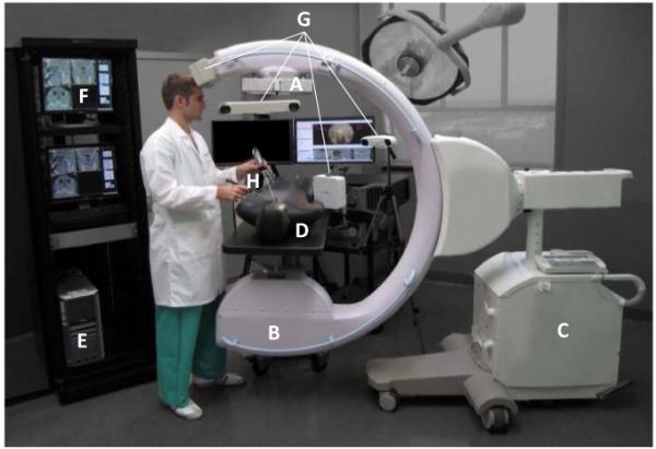
Photograph of a prototype C-arm for 3D intraoperative imaging. Components of the system include: (A) the FPD (PaxScan 3030+, Varian Inc. Palo Alto USA); (B) the x-ray tube, filtration, and collimator; (C) the mobile C-arm platform, gantry, and generator (PowerMobil, Siemens Healthcare, Erlangen Germany); (D) the patient (phantom) on a radiolucent (carbon-fiber) operating table; (E) a computer workstation for image acquisition, reconstruction, registration, and navigation;(F) displays for visualization of preoperative and intraoperative images, planning data, and real-time navigation; (G) any of an assortment of real-time tracking technologies [e.g., Polaris or Aurora (NDI, Mississauga Canada) or MicronTracker (Claron, Toronto Canada); and (H) trackable instruments – e.g., surgical tools and a video endoscope.
II. THEORETICAL METHODS
A. An Image Science Framework for Tomosynthesis and Cone-Beam CT
Cascaded systems analysis models the imaging chain as a serial and/or parallel cascade of physical or mathematical processes that change the mean, statistical distribution, or spatial distribution of image quanta, and it is a fairly well established means of modeling important imaging performance characteristics for FPDs. The basis of such analysis traces to Rabbani et al.7 who described the propagation of spatial-frequency-dependent signal and noise in processes related to amplification (or loss) and stochastic scatter (i.e., blur). Cunningham et al.8 elucidated and helped to popularize the concept in application to x-ray imaging systems, and the formalism was expanded and refined through the course of the 1990s to include effects of sampling (aliasing) in application to FPDs.9-17 As these detectors proliferated in advanced imaging applications such as tomosynthesis and CBCT, so too did the modeling of imaging performance – e.g., early work by Siewerdsen et al.,18-20 Tward et al.,21,22 Zhao et al.,23 and Gang et al.24-25 An illustration of a cascaded systems model for FPD-based CBCT is shown in Fig. 2.
Figure 2.

Illustration of cascaded systems analysis framework for modeling 3D image quality in FPD-based tomosynthesis and CBCT. Each stage in the cascade represents a physical or mathematical process affecting the propagation of signal and noise in the imaging chain. The portion within the gray box represents the 2D projection imaging chain, followed by the 3D reconstruction chain of filtered backprojection. The model allows analysis of NPS, NEQ, and detectability index (d’) as a function of various system design parameters (e.g., detector readout mode), exposure conditions (e.g., kVp and dose), and reconstruction parameters (e.g., reconstruction filter and voxel size).
Each stage in the diagram represents a process of gain, scatter, integration, or sampling for which the propagation of the spatial-frequency-dependent NPS is, respectively:
| (1) |
| (2) |
| (3) |
| (4) |
where i represents a particular stage in the cascade, is the mean number of image quanta at stage i, and f is spatial-frequency (a 2D or 3D domain for projection or reconstruction images, respectively). The parameters , , MTFi, and IIIi are the gain, gain-variance, modulation transfer function (MTF), and sampling function that govern propagation of the NPS for a particular stage. Details of the analysis, including derivation of the NPS for the complete imaging chain are in Ref. 11 for 2D projections, Refs. 23-25 for tomosynthesis, and Ref. 21-22 for 3D CBCT reconstruction.
B. Implications for System Design and Translation to Clinical Applications
The model of Fig. 2 has demonstrated agreement with measurement of the 2D and 3D image NPS and NEQ over a broad range of imaging conditions and reconstructions parameters. The NPS derived from Eqs. (1)-(4) applied to the cascade of Fig. 2 is related to the 3D NEQ according to the MTF and incident x-ray fluence (which, in turn, relates to dose):
| (5) |
where we have factored terms πf to show cancellation of the ramp filter (|fr|) in the NPS, giving a 3D NEQ that is typically a smooth, monotonically decreasing function of spatial-frqeuency; furthermore, we have factored terms (the product of the number of projections and incident x-ray fluence per projection) to show an explicit (monotonically increasing) dependence of NEQ on dose. The latter factor is usually considered within a ‘normalized’ NPS in the denominator. The NEQ provides a useful figure of merit for the spatial-frequency-dependent signal-to-noise ratio (SNR) in CBCT that considers each factor of the imaging chain, from the incident energy and fluence of the x-ray beam all the way through to the choice of reconstruction filter and voxel size.
The NEQ may be further generalized to include anatomical background fluctuations as an additional power spectrum in the denominator to the extent that such image fluctuations diminish performance of the task. The most common form taken for the anatomical background power spectrum is power-law:
| (6) |
where κ describes the magnitude of background noise and β its spatial frequency content. A value of β ~3 has been commonly measured in breast radiography and CT, corresponding to the theoretical prediction of a self-similar fractal pattern.25 By adding the background power spectrum to the quantum noise in the denominator of Eq. (5), we obtain a “generalized” NEQ that suggests two dose regimes: a low-dose regime in which SNR is governed by quantum noise and a high-dose regime in which SNR is limited by anatomical background. In the former, factors of blur, sampling, additive noise, and the myriad of imaging chain parameters in Fig. 2 are intertwined in system performance; in the latter regime, fluctuations within the object itself are the limiting factor in detectability, and increasing dose will not improve task performance. An analogy is walking a path in the forest: at night (the low-dose regime in which the detector is starved for photons), navigating the path is limited by one’s ability to see in the dark; during the day (the high-dose regime), navigating the path is limited by the trees themselves.
The generalized NEQ relates to the fidelity of SNR(f) transfer through the imaging chain and can be extended further to a metric of task-based detectability by weighing the NEQ by a task function describing the spatial-frequencies of importance in accomplishing a given task:
| (7) |
where for 3D CBCT, a 3D Fourier domain (f) and 3D integral are implied. The task function, Wtask(f), is an idealized approximation of the spatial-frequencies that a model (or real) observer uses in accomplishing the task. The simplest model for such is a binary hypothesis testing approach in which the observer chooses between two possible hypotheses, H1(x) and H2(x), representing images of “normal” and “abnormal” cases, respectively, or more commonly “signal-present” and “noise-only” cases. The task function is given by Fourier transform of the difference in hypotheses:
| (8) |
While this represents perhaps the simplest possible representation of task-based performance metrology, it has demonstrated agreement with real observer response over a fairly broad range of experimental conditions and simple imaging tasks in dual-energy imaging, tomosynthesis, and CBCT.24,34 The assumptions and limitations of the approach are similarly considerable, including assumptions of linearity, shift invariance, and wide-sense stationarity with which images reconstructed by filtered backprojection are known not to strictly comply. However, within the constraints of a “local” estimation, the NPS and related metrics of NEQ and d’ have been shown to be reasonable approximations of the image signal and noise characteristics.
The relevance of such modeling to system design should be clear. The NPS, NEQ, and d’ encapsulate imaging performance metrics that can be related to detectability (e.g., of a high-contrast bone detail or a low-contrast soft-tissue interface) as a function of any parameter in the imaging chain. The framework thus provides the system designer with an objective function for system optimization. For example, the analysis can be used to describe detectability as a function of beam characteristics (e.g., kVp and dose), system configuration (e.g., detector selection and system geometry), and reconstruction technique (e.g., choice of reconstruction filter). While there are numerous image quality factors not included in such analysis (most notably, image artifacts and object motion) the framework provides a basis for understanding the fundamental factors governing imaging performance. Examples in relation to the design and operation of the CBCT C-arm in Fig. 1 are shown below, specifically examining task-based detectability as a function of system parameters relating to dose.
III. EXPERIMENTAL METHODS
A. A Prototype Mobile C-Arm for High-Performance Intraoperative Cone-Beam CT
The C-arm prototype in Fig. 1 represents an evolution of previous 3D-capable C-arms using an x-ray image intensifier (XRII). Such previous implementations were fairly limited in image quality and FOV but were suitable to a variety of applications (e.g., certain orthopaedic surgeries) for which high-contrast structures within a limited FOV were of primary concern. The prototype in Fig. 1 was based on a larger C-arm platform with increased power (Siemens PowerMobil) and underwent a number of modifications to permit high-quality CBCT: i.) the x-ray tube window was increased to allow a larger FOV; ii.) added filtration (Al and Cu) was introduced to give a harder x-ray beam; iii.) the XRII was replaced with a FPD – a 41×41 cm2 RID1640 (PerkinElmer, Santa Clara CA) in the earliest version,35,36 followed by a 40×30 cm2 PaxScan 4030CB and 30×30 cm2 PaxScan 3030+ (Varian, Palo Alto CA) in later implementations;33,37-43 iv.) the C-arm gantry was motorized under computer control; v.) a system for geometric calibration was developed;6 vi.) a computer workstation was implemented for synchronization of continuous gantry rotation, FPD readout, and pulsed x-ray exposure; vii.) 3D reconstruction methods were implemented based on variations of the FDK algorithm; and vii.) the system was integrated with an advanced surgical navigation system, including real-time tracking, image registration, video augmentation, and multi-modality visualization. As illustrated below, the C-arm prototype demonstrates sub-mm spatial resolution and the capability for soft-tissue visualization, although the latter stands to benefit significantly from advanced reconstruction and artifact correction techniques. The system was evaluated extensively in laboratory testing of image quality, radiation dose, geometric accuracy, etc. and preclinical evaluation was examined in applications such as prostate brachytherapy,36 orthopaedic surgery of the knee, femur, and spine,33,44-45 thoracic surgery, ear surgery (e.g., cochlear implant), endoscopic sinus surgery, head-and-neck surgery, and skull base surgery.41-43 Early clinical trials were performed in prostate brachytherapy and head-and-neck surgery.
B. An Integrated Surgical Guidance System
An imaging system is only the first step in the development of an image-guidance system. For high-quality 3D intraoperative imaging to be of real value in broad application, it must integrated with a surgical navigation system, and the entire system must in turn be integrated with surgical workflow. The availability of near-real-time imaging in the OR also presents an opportunity for the development of advanced, high-performance navigation technologies, some of which are illustrated in Fig. 3 and summarized below.
Figure 3.

(left) Photograph of a surgeon performing endoscopic skull base surgery in a cadaver specimen under C-arm CBCT guidance. (right) Screenshot of software interface integrating 3D imaging, tracking, registration, and endoscopic video-augmentation.
1. Software Architecture for System Integration
Software for surgical navigation has benefited tremendously from open-source libraries that accelerate the development of tools and interfaces for common tracking, navigation, and visualization tasks. Examples include VTK, ITK, and IGSTK (Kitware Inc., Clifton Park NY), CISST libraries (Johns Hopkins University, Baltimore MD), and 3D Slicer (Brigham and Women’s Hospital, Boston MA). The software platform integrating C-arm CBCT capability with advanced navigation tools combines CISST libraries for real-time tracking, bound by high-level programming (Python) to a front-end based on 3D Slicer for multi-modality image visualization and analysis. The resulting software architecture (referred to nominally as TREK) accelerates translation of task-specific modules from the laboratory to preclinical testing and evaluation (including each of the subsystems below), analyzes factors such as geometric precision in real-time to minimize offline data processing, and provides a flexible visualization front-end that may be adapted quickly to various surgical application requirements.
2. 3D Image Registration
With each intraoperative CBCT scan, there is a wealth of previous image and planning data that should be registered to the context of the most recent image data. This includes preoperative images (e.g., CT, MR, and PET), preoperative planning data (e.g., segmentation of the surgical target and critical anatomy, surgical tool trajectories, and planned incisions), and previous intraoperative CBCT images. The simplest method is rigid registration (i.e., 3D translation and rotation), using either a collection of corresponding point sets or the image data directly; however, rigid registration fails to account for deformation that occurs during the procedure. All of the surgical applications mentioned above are subject to such deformations – even head-and-neck / skull base surgery, where the deformations owing to jaw flexion, neck flexion, and herniation of the orbital walls and other structures in the sinonasal space are common during surgery – and among the main advantages of intraoperative CBCT is the ability to properly update the image data to correctly reflect such tissue changes. Deformable 3D image registration is essential to making full use of previous image and planning data but can require computing times in excess of the requirements of intraoperative use. A promising method involves new implementations of the Demons algorithm,46 a form of optical flow that uses image intensity gradients to warp a previous (“moving”) image to the current (“fixed”) CBCT. Recent developments include implementation within a hierarchical morphological pyramid and a “smart” convergence criterion within the iterative process to improve computing time to levels consistent with intraoperative use. The approach has been further modified to match preoperative CT to intraoperative CBCT in a manner that is robust against image intensity mismatches between the two modalities, thereby allowing fast deformable registration of any other preoperative CT-registered image or planning data to the most up-to-date CBCT.
3. Surgical Tracking, Visualization, and Navigation
A spectrum of real-time surgical tracking modalities are available as illustrated in Fig. 1, each with certain advantages to different surgical applications. These include stereoscopic infrared tracking (e.g., Polaris Spectrum and Vicra, NDI, Mississauga ON), stereoscopic video (e.g., Claron MicronTracker, Toronto ON), and electromagnetic tracking (e.g,. Aurora, NDI, Mississauga ON). Each of these technologies has been integrated within the TREK navigation platform, and novel adaptations are being pursued for specific surgical applications. For example, in skull base surgery, an infrared tracker is used to track the orientation of a sinus endoscope, allowing augmentation of endoscopic video with image and planning data with accuracy ~2 mm; the accuracy is improved (better than 1 mm) through derivation of a 3D video surface using structure-from-motion techniques, followed by direct 3D-3D registration of video to CBCT. In spine surgery, a video-based tracker mounted directly on the C-arm gantry provides: tracking with improved line-of-sight compared to a conventional setup; video-augmented views from any angle about the patient; and a variety of surgical assistance tools, including digitally reconstructed radiographs (DRRs) computed from the perspective of any tracked tool to provide real-time “virtual fluoroscopy.” In thoracic surgery, an electromagnetic tracker allows navigation using flexible instruments inside the body (e.g., a bronchoscope) and is being implemented in a hybrid arrangement with infrared and/or video trackers to increase geometric accuracy and provide tracking that is robust against electromagnetic field distortion or line-of-sight occlusion.
The system described above presents the surgeon with a possibly overwhelming mass of multi-modality image, planning, and navigation data – not unlike a fighter pilot in terms of the potential information bombardment and need to integrate for real-time decision-making with a high cost of failure. Image display featuring tri-planar views and various surface, volume, or maximum-intensity-projection (MIP) views is a starting point, but in many applications the video scene presented by an endoscope, laparoscope, thoracoscope, or similar video source is potentially the most natural interface to such multi-modality information. In endoscopic skull base surgery, for example, the video scene may be augmented with image and planning data via the combined tracking and direct 3D registration approaches described above. The ability to highlight the surgical target and surrounding critical structures, planning data, and other data types directly within the video scene provides a wealth of information in an integrated form that is a natural extension of the surgeon’s toolkit – analogous to the fighter pilot’s heads-up display.
IV. RESULTS
A. C-Arm Cone-Beam CT Image Quality and Dose
Figure 4 shows calculations of NEQ and detectability index as a function of dose, illustrating the ability of the cascaded systems framework to identify low-dose limits for imaging of various tasks under a broad range of acquisition and reconstruction techniques. In Fig. 4(a), the generalized (zero-frequency) NEQ is seen to increase sharply with dose up to ~3-4 mGy followed by a modest slope and a plateau above ~10 mGy. This behavior corresponds to a low-dose regime in which image quality is dominated by quantum noise and a high-dose regime in which detectability is limited by fluctuations within the anatomical background. Recognizing the “low-dose limit” – i.e., the dose beyond which further increase will not improve image quality is a fundamental step in determining low-dose imaging performance.
Figure 4.

Calculations of (a) NEQ and (b) detectability index. Cascaded systems analysis of imaging performance serves to identify the factors in the image acquisition and reconstruction chain that limit performance and can be used to identify low-dose imaging protocols consistent with a given task.
The analysis is extended to task-based detectability in Fig. 4(b), where d’ is plotted for two imaging tasks – a high-contrast bone detail detection task and a low-contrast soft-tissue detection task. The former exhibits higher detectability overall due to the higher contrast of the stimulus and increases with dose, since the high-frequency stimulus (a Ca “delta function” in fat) corresponds to a task function distinct from the anatomical background and therefore limited primarily by quantum noise. The latter exhibits lower detectability and a shallower dose dependence overall, corresponding to a low-frequency task (a ~3 mm fat-muscle stimulus) for which the task function resides in the same low-frequency regime as the one-over-f anatomical background – i.e., the stimulus “masquerades” as anatomical noise. Taking a level of d’ in the range ~1-1.5 as corresponding to basic conspicuity, we find a separate low-dose limit for each task – viz., D ~1 mGy for the high-contrast bone task and D ~3-4 mGy for the low-contrast soft-tissue visualization task.
These findings suggest a simple strategy for intraoperative scanning protocols that minimize dose while maintaining task performance. For a given body habitus and anatomical site, the surgeon should decide prior to each scan as to the imaging task – i.e., is the scan intended to visualize high-contrast structures (e.g., an instrument in bony anatomy), or is the scan intended to visualize soft-tissue structures (e.g., a check for residual tumor). The CBCT scan protocol (specifically, selection of kVp, mAs, and number of projections) can be thereby selected in a manner sufficient for the task but minimal in dose.
The soft-tissue imaging characteristics are illustrated qualitatively in Fig. 5. The images correspond to conditions that are free of patient motion (cadaveric specimens) but with a minimum of post-processing and artifact correction. Artifacts clearly seen in Fig. 5 include those arising from x-ray scatter, beam hardening, and cone-beam effects – e.g., dark streaks arising from bone edges – illustrating “raw” image quality in C-arm CBCT reconstructions. The images are qualitatively consistent with the analysis of Fig. 4 (i.e., soft-tissue visibility in the dose range ~3-5 mGy) and suggest the potential for soft-tissue visibility approaching that of diagnostic CT as detector technology, reconstruction techniques, and artifact correction methods improve. The visibility of high-contrast bone features is also illustrated in Fig. 5, although the reconstruction parameters (viz., reconstruction filter and voxel size) and window-level display were adjusted for soft-tissue visualization. The ability of C-arm CBCT to resolve sub-mm detail with nearly isotropic spatial resolution has been fairly well established in previous work, consistent with the “High-Contrast Detail” curve of Fig. 4 and evident in the translation of C-arm CBCT to applications where bone visualization is the primary task – e.g., orthopaedic surgery.
Figure 5.

Example C-arm CBCT images in regions of the (a) head and neck, (b,c) lumbar spine, (d) abdomen, and (e,f) knee. Images (c) and (d) were adapted from studies performed in Reference 39 with permission from the authors. Each image was obtained in cadaver studies intended to demonstrate basic soft-tissue image quality characteristics without correction of artifacts such as x-ray scatter, beam hardening, and cone-beam artifacts – each of which is evident (e.g., dark streaks about regions of bone). In this sense, the images represent “raw” CBCT reconstructions and stand to benefit significantly from artifact correction. Fat-muscle interfaces are clearly delineated, as are various soft-tissue organs (e.g., kidney and liver) and tendons.
B. Translation of C-Arm Cone-Beam CT to Surgical Applications
With a knowledge of the fundamental factors governing C-arm CBCT imaging performance and driven by specific clinical tasks in image-guided surgery, the C-arm has been applied in a spectrum of surgical applications where high-quality intraoperative 3D imaging could improve surgical performance through enhanced visualization and geometric precision. Applications illustrated below include endoscopic head-and-neck / skull base surgery as well as spine / orthopaedic surgery. Ongoing work includes application to thoracic surgery (e.g., guiding resection of subpalpable lung nodules) and abdominal interventions in the liver and kidney (e.g., integration with ultrasound imaging in guidance of radiofrequency ablation and partial nephrectomy).
Application to endoscopic skull base surgery is illustrated in Fig. 3 (above), showing improved visualization of the surgical target and critical anatomy through 3D registration of C-arm CBCT with surgical planning data (colored segmentations) and video-CT augmentation (carotid arteries rendered in pink within the endoscopic scene). A series of CBCT images acquired in the course of a cadaver experiment in which C-arm CBCT was used to guide skull base ablation (clivus drillout) is illustrated in Fig. 6. The key image quality characteristics in this application are the capability for sub-mm spatial resolution and a modest degree of soft-tissue visibility at low radiation dose. Consistent with the NEQ analysis above and as shown by Daly et al.,38 C-arm CBCT images may be acquired according to a “task-based” protocols that impart a minimum radiation dose consistent with the performance of a given task – e.g., “Low-Dose” and “High-Quality” protocols for visualization of bony features and soft-tissues, respectively. The resulting scan protocols involve radiation dose that is a fraction of that in diagnostic CT – e.g., ~3 mGy (0.10 mSv) for bone visualization and ~10 mGy (0.34 mSv) for soft-tissue visualization. Such task-based protocols allow repeat intraoperative scanning such that the total dose imparted in the course of the operation (e.g., involving ~4-6 scans) is less than a single diagnostic CT scan (~40 mGy, ~1.5 mSv).
Figure 6.

Example cadaver images from preclinical studies of C-arm CBCT guidance in skull base surgery. Top row: sagittal slice. Middle row: axial slice. Bottom row: zoomed-in image about a region of interest. Pink arrows denote features of interest at each step of the skull base ablation. (a)Initial CBCT acquired immediately prior to intervention. (b) CBCT acquired following excision of anterior and posterior ethmoid sinus air cells. (c)CBCT acquired in the course of a drillout about the right vidian nerve. (d) The same, about the left vidian. (e) CBCT image guiding drillout of the middle clivus under the objective of maintaining a thin (~1 mm) margin of the posterior clivus. (f) The same, in the lower clivus.
Among the first applications of XRII-based C-arms capable of 3D imaging was spine surgery, and the benefits to minimally invasive approaches stand to increase considerably due to advanced C-arm platforms featuring improved spatial resolution, soft-tissue imaging, lower radiation dose, larger FOV, and better integration with surgical navigation systems. Again guided by analysis of task-based detectability index (Fig. 4) and experimentation in phantoms and cadavers (Fig. 5-7), task-based protocols can be defined to minimize radiation dose to a level consistent with the imaging task. As illustrated in Fig. 7, low-dose CBCT scan protocols imparting ~1 mGy (~0.2 mSv) are sufficient for visualization of high-contrast bony details, whereas high-quality scan protocols (~5 mGy, ~1.1 mSv) provide increased soft-tissue visualization. Again, these dose levels are such that a complete operation involving several CBCT scans can be completed with total dose less than that typical of diagnostic thoracic or abdominal CT (>60 mGy, ~13 mSv). Furthermore, these dose levels are less than that reported for other C-arm systems applied to similar anatomical sites, suggesting the potential for dose reduction in other applications.
Figure 7.
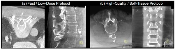
Example images in phantom and cadaver illustrating image quality characteristics associated with (a) fast / low-dose protocols for visualization of high-contrast bone details, and (b) high-quality / higher dose protocols for visualization of soft tissues.
Among the barriers to broad clinical acceptance of image guidance and navigation technologies is a lack of streamlined integration and disruption of surgical workflow. In addition to the image quality advantages offered by high-performance C-arm CBCT, therefore, is a need for integration not only with other intraoperative technologies (viz., real-time tracking and 3D visualization) but also with the broader context of the hospital information system in order to combine intraopertative CBCT with preoperative image and planning data as well as to convey intraoperative utilization to the clinical PACS for postoperative review. The availability of high-quality imaging in the OR also presents an opportunity for the development of advanced visualization and navigation techniques, e.g., high-precision tracking based on multi-modality (e.g., infrared and electromagnetic) trackers, real-time visualization of tools within up-to-date CBCT, augmentation of CBCT with preoperative CT or MR, video augmentation providing overlay of image and planning data within a video scene (e.g., using the video-based tracker as a video source), and real-time DRRs providing “virtual fluoroscopy” as a navigation assistant. Some of these capabilities are illustrated in the context of CBCT-guided spine surgery in Fig. 8.
Figure 8.

Illustration of enhanced navigation functionality integrated with C-arm CBCT. (top left) CBCT images about the lumbar spine showing transpedicular placement of a needle (e.g., for vertebroplasty) and real-time tracking in the context of slices or a MIP rendering. (upper right) zoomed-in view of real-time pointer tracking within the CBCT MIP. (lower left) Video augmentation illustrated in a chest phantom in which preoperative CT image information (e.g., segmented spine and ribs) is overlaid in the video scene along with CBCT, planning data (segmented target vertebrae), and real-time tracking (pointer tool). (lower right) Illustration of vide-augmented views, real-time DRR “virtual fluoroscopy” and registration of preoperative CT with intraoperative CBCT.
V. DISCUSSION AND CONCLUSIONS
The work presented above represents a fairly broad arc of research over the last decade toward the development of high-quality, low-dose CBCT for surgical guidance. The work is grounded in quantitative analysis of imaging performance, including cascaded systems analysis of the image chain to identify fundamental factors governing image quality, provide a guide to system optimization, and help identify low-dose imaging techniques consistent with the imaging task. Such analysis provides an important theoretical counterpart to preclinical measurements of image quality and dose in phantoms and cadavers. Recent work demonstrates basic agreement between task-based cascaded systems model calculations and the performance of real observers in tomosynthesis and CBCT over a broad range of conditions and imaging tasks, supporting the utility of such an approach in future system development.
The translation of a prototype C-arm for high-performance CBCT has benefited from such analysis combined with experimental studies conducted within a broad range of specific surgical applications. In each case, low-dose imaging protocols are defined according to the surgical task to allow repeat intraoperative CBCT such that total dose delivered over the course of the procedure is minimized. Integration of such protocols and the guidance system as a whole within the surgical workflow is critical to overcoming conventional barriers to clinical acceptance. For example, it may be unreasonable to require a surgeon to select from a “technique chart” for each scan; however, a simple selection between “bone” or “soft tissue” with each scan (depending on the level of image quality required for a given task) is practical, and the burden is shifted to software and a capable technologist to select technique factors (e.g., kVp, mAs, reconstruction filter, etc.) according to patient size and anatomical site.
Similarly, the imaging system must demonstrate a high level of integration with the associated navigation system – from basic calibration to registration with preoperative data, real-time tracking, and streamlined multi-modality display. While the introduction of intraoperative imaging might at first be seen as yet one more system added to an already complex navigation system, such technology, in fact, presents an opportunity for greater integration and simplification within the surgical workflow. A simple example is automatic registration of the tracking system to the patient: whereas a conventional, manual registration based on fiducial points is a somewhat cumbersome process subject to degradation in precision through the course of the operation, C-arm CBCT presents a method for automatically computing the registration with each scan.47 Similarly, novel tracking configurations integrated with the C-arm present possibilities for less obtrusive implementations that can operate more invisibly and make real-time navigation a more natural extension of the surgeon’s tools. Furthermore, precise registration and overlay of image and planning data directly within a video / endoscopic scene provides a natural interface to multiple sources of information in a manner that can be interpreted more rapidly than in conventional display formats (e.g., triplanar views plus a volume rendering). The key advance presented by such technology is to overcome the basic limitation of conventional image-guided surgery by providing guidance within an up-to-date image that properly reflects intraoperative change. Such capability combined with well integrated navigation systems offers to extend high-precision surgical approaches to conventionally inoperable cases, facilitate the development of new interventional approaches requiring a high degree of surgical precision, and improve patient safety.
ACKNOWLEDGMENTS
The research was supported by the National Institutes of Health Grants R01-CA-112163 and R01-CA-127944 and collaboration with Siemens Healthcare (Erlangen, Germany). The work resulted from contributions of faculty, staff, and collaborators spanning a decade of research. Ms. Grace Jianan Gang, Mr. Daniel J. Tward, and Mr. Prakhar Prakash (Johns Hopkins University) contributed to the development of cascaded systems analysis models for 3D imaging. The C-arm prototype was developed in collaboration with scientists at Siemens XP (Erlangen, Germany), including Dr. Clemens Bulitta, Dr. Rainer Graumann, Dr. Dieter Ritter, Dr. Christian Schmidgunst, Dr. Gerhard Kleinszig, and Dr. Mathias Mitschke, as well as collaborators at the University Health Network (Toronto, Canada), including Dr. David Jaffray, Dr. Jonathan Irish, and Mr. Michael Daly. The most recent work in clinical translation and development of high-performance surgical navigation based on C-arm CBCT was performed in collaboration with clinicians, faculty, and students at Johns Hopkins University: Dr. Gary Gallia, Dr. Douglas Reh, and Dr. Stella Lee in endoscopic skull base surgery; Dr. Jay Khanna in spine and orthopaedic surgery; Dr. Marc Sussman in thoracic surgery; Dr. Russ Taylor in computer-integrated surgery; Dr. Greg Hager in video-CT registration; Dr. Sebastian Schafer in 3D image quality and dose; and Mr. Sajendra Nithiananthan, Mr. Ali Uneri, Mr. Daniel J. Mirota, Ms. Sureerat Reaungamornrat, and Mr. Jongheun Yoo in the development of advanced image registration, tracking, and video augmentation techniques.
Footnotes
Publisher's Disclaimer: This is a PDF file of an unedited manuscript that has been accepted for publication. As a service to our customers we are providing this early version of the manuscript. The manuscript will undergo copyediting, typesetting, and review of the resulting proof before it is published in its final citable form. Please note that during the production process errors may be discovered which could affect the content, and all legal disclaimers that apply to the journal pertain.
REFERENCES
- 1.Feldkamp LA, Davis LC, Kress JW. Practical cone-beam algorithm. J.Opt.Soc.Am.A. 1984;1:612–619. [Google Scholar]
- 2.Fahrig R, Holdsworth DW. Three-dimensional computed tomographic reconstruction using a C-arm mounted XRII: image-based correction of gantry motion nonidealities. Medical Physics. 2000;27(1):30–38. doi: 10.1118/1.598854. [DOI] [PubMed] [Google Scholar]
- 3.Noo F, Clackdoyle R, Mennessier C, White TA, Roney TJ. Analytic method based on identification of ellipse parameters for scanner calibration in cone-beam tomography. Physics in Medicine & Biology. 2000;45(11):3489–3508. doi: 10.1088/0031-9155/45/11/327. [DOI] [PubMed] [Google Scholar]
- 4.Navab N, Bani-Hashemi A, Mitschke M. Dynamic Geometric Calibration for 3-D Cerebral Angiography. Proc.SPIE Medical Imaging. 1996;3708:361–370. [Google Scholar]
- 5.Cho Y, Moseley DJ, Siewerdsen JH, Jaffray DA. Accurate technique for complete geometric calibration of cone-beam computed tomography systems. Medical Physics. 2005;32(4):968–983. doi: 10.1118/1.1869652. [DOI] [PubMed] [Google Scholar]
- 6.Daly MJ, Siewerdsen JH, Cho YB, Jaffray DA, Irish JC. Geometric calibration of a cone-beam CT-capable mobile C-arm. Med. Phys. 2008;35(5):2124–2136. doi: 10.1118/1.2907563. [DOI] [PMC free article] [PubMed] [Google Scholar]
- 7.Rabbani M, Shaw R, Van Metter R. Detective quantum efficiency of imaging systems with amplifying and scattering mechanisms. J.Opt.Soc.Am.A. 1987;4(5):895–901. doi: 10.1364/josaa.4.000895. [DOI] [PubMed] [Google Scholar]
- 8.Cunningham IA, Westmore MS, Fenster A. A spatial-frequency dependent quantum accounting diagram and detective quantum efficiency model of signal and noise propagation in cascaded imaging systems. Medical Physics. 1994;21(3):417–427. doi: 10.1118/1.597401. [DOI] [PubMed] [Google Scholar]
- 9.Siewerdsen JH, Antonuk LE, El Mohri Y, Yorkston J, Huang W, Boudry JM, Cunningham IA. Empirical and theoretical investigation of the noise performance of indirect detection, active matrix flat-panel imagers (AMFPIs) for diagnostic radiology. Medical Physics. 1997;24(1):71–89. doi: 10.1118/1.597919. [DOI] [PubMed] [Google Scholar]
- 10.Zhao W, Rowlands JA. Digital radiology using active matrix readout of amorphous selenium: theoretical analysis of detective quantum efficiency. Medical Physics. 1997;24(12):1819–1833. doi: 10.1118/1.598097. [DOI] [PubMed] [Google Scholar]
- 11.Siewerdsen JH, Antonuk LE, El Mohri Y, Yorkston J, Huang W, Cunningham IA. Signal, noise power spectrum, and detective quantum efficiency of indirect-detection flat-panel imagers for diagnostic radiology. Medical Physics. 1998;25(5):614–628. doi: 10.1118/1.598243. [DOI] [PubMed] [Google Scholar]
- 12.Vedantham S, Karellas A, Suryanarayanan S, Albagli D, Han S, Tkaczyk EJ, Landberg CE, Opsahl-Ong B, Granfors PR, Levis I, D’Orsi CJ, Hendrick RE. Full breast digital mammography with an amorphous silicon-based flat panel detector: physical characteristics of a clinical prototype. Medical Physics. 2000;27(3):558–567. doi: 10.1118/1.598895. [DOI] [PMC free article] [PubMed] [Google Scholar]
- 13.Yao J, Cunningham IA. Parallel cascades: new ways to describe noise transfer in medical imaging systems. Medical Physics. 2001;28(10):2020–2038. doi: 10.1118/1.1405842. [DOI] [PubMed] [Google Scholar]
- 14.Zhao W, Ji WG, Rowlands JA. Effects of characteristic x rays on the noise power spectra and detective quantum efficiency of photoconductive x-ray detectors. Medical Physics. 2001;28(10):2039–2049. doi: 10.1118/1.1405845. [DOI] [PubMed] [Google Scholar]
- 15.Zhao W, Ji WG, Debrie A, Rowlands JA. Imaging Performance of Amorphous Selenium Based Flat-Panel Detectors for Digital Mammography: Characterization of a Small Area Prototype Detector. Med Phys. 2003;30(2):254–263. doi: 10.1118/1.1538233. [DOI] [PubMed] [Google Scholar]
- 16.Vedantham S, Karellas A, Suryanarayanan S. Solid-state fluoroscopic imager for high-resolution angiography: parallel-cascaded linear systems analysis. Medical Physics. 2004;31(5):1258–1268. doi: 10.1118/1.1689014. [DOI] [PMC free article] [PubMed] [Google Scholar]
- 17.Ganguly A, Rudin S, Bednarek DR, Hoffmann KR. Micro-angiography for neuro-vascular imaging. II. Cascade model analysis. Medical Physics. 2003;30(11):3029–3039. doi: 10.1118/1.1617550. [DOI] [PubMed] [Google Scholar]
- 18.Siewerdsen JH, Jaffray DA. Optimization of x-ray imaging geometry (with specific application to flat-panel cone-beam computed tomography. Med. Phys. 2000;27(8):1903–1914. doi: 10.1118/1.1286590. [DOI] [PubMed] [Google Scholar]
- 19.Siewerdsen JH, Jaffray DA. Cone-beam computed tomography with a flat-panel imager: noise considerations for fully 3-D imaging. SPIE Physics of Medical Imaging. 2000;3336:546–554. [Google Scholar]
- 20.Siewerdsen JH, Jaffray DA. Three-dimensional NEQ transfer characteristics of volume CT using direct and indirect-detection flat-panel imagers. SPIE Physics of Medical Imaging. 2003;5030:92–102. [Google Scholar]
- 21.Tward DJ, Siewerdsen JH. Cascaded systems analysis of the 3D noise-power spectrum of flat-panel cone-beam CT. Med. Phys. 2008;35(12):5510–5529. doi: 10.1118/1.3002414. [DOI] [PMC free article] [PubMed] [Google Scholar]
- 22.Tward DJ, Siewerdsen JH. Noise aliasing and the 3D NEQ of flat-panel cone-beam CT: Effect of 2D/3D apertures and sampling. Med. Phys. 2009;36(8):3830–3843. doi: 10.1118/1.3166933. [DOI] [PMC free article] [PubMed] [Google Scholar]
- 23.Zhao B, Zhao W. Three-dimensional linear system analysis for breast tomosynthesis. Med.Phys. 2008;35(12):5219–5232. doi: 10.1118/1.2996014. [DOI] [PMC free article] [PubMed] [Google Scholar]
- 24.Gang GJ, Lee J, Tward DJ, Siewerdsen JH. The generalized NEQ and detectability index for tomosynthesis and cone-beam CT: From cascaded systems analysis to human observers. Proc. SPIE Physics of Medical Imaging. 2010;7622(76220Y-1):8. doi: 10.1117/12.845462. [DOI] [PMC free article] [PubMed] [Google Scholar]
- 25.Gang GJ, Tward DJ, Lee J, Siewerdsen JH. Anatomical background and generalized detectability in tomosynthesis and cone-beam CT. Med. Phys. 2010;37(5):1948–1965. doi: 10.1118/1.3352586. [DOI] [PMC free article] [PubMed] [Google Scholar]
- 26.Katsevich A. Analysis of an exact inversion algorithm for spiral cone-beam CT. Phys Med Biol. 2002;47(15):2583–97. doi: 10.1088/0031-9155/47/15/302. [DOI] [PubMed] [Google Scholar]
- 27.Chen GH. An alternative derivation of Katsevich’s cone-beam reconstruction formula. Med. Phys. 2003;30:3217. doi: 10.1118/1.1628413. [DOI] [PubMed] [Google Scholar]
- 28.Bontus C, Köhler T, Proksa R. A quasiexact reconstruction algorithm for helical CT using a 3-Pi acquisition. Med. Phys. 2003;30:2493–2502. doi: 10.1118/1.1601913. [DOI] [PubMed] [Google Scholar]
- 29.Pan X, Zou Y, Xia D. Image reconstruction in peripheral and central regions-of-interest and data redundancy. Med. Phys. 2005;32:673–684. doi: 10.1118/1.1844171. [DOI] [PubMed] [Google Scholar]
- 30.Yu H, Zhao S, Ye Y, Wang G. Exact BPF and FBP algorithms for nonstandard saddle curves. Med. Phys. 2005;32:3305–3312. doi: 10.1118/1.2074207. [DOI] [PubMed] [Google Scholar]
- 31.Jaffray DA, Siewerdsen JH, Wong JW, Martinez AA. Flat-panel cone-beam computed tomography for image-guided radiation therapy. Int. J. Radiat. Oncol. Biol. Phys. 2002;53(5):1337–1349. doi: 10.1016/s0360-3016(02)02884-5. [DOI] [PubMed] [Google Scholar]
- 32.Fahrig R, Dixon R, Payne T, Morin RL, Ganguly A, Strobel N. Dose and image quality for a cone-beam C-arm CT system. Med Phys. 2006;33(12):4541–50. doi: 10.1118/1.2370508. [DOI] [PubMed] [Google Scholar]
- 33.Siewerdsen JH, Moseley DJ, Burch S, Bisland SK, Bogaards A, Wilson BC, Jaffray DA. Volume CT with a flat-panel detector on a mobile, isocentric C-arm: Pre-clinical investigation in guidance of minimally invasive surgery. Med. Phys. 2005;32(1):241–254. doi: 10.1118/1.1836331. [DOI] [PubMed] [Google Scholar]
- 34.Richard S, Siewerdsen JH. Comparison of model and human observer performance for detection and discrimination tasks using dual-energy x-ray images. Med. Phys. 2008;35(11):5043–5053. doi: 10.1118/1.2988161. [DOI] [PMC free article] [PubMed] [Google Scholar]
- 35.Siewerdsen JH, Edmundson GK, Sanders WP, Wong JW, Martinez AA, Jaffray DA. Flat-panel cone-beam CT: A novel imaging technology for image-guided procedures. SPIE Medical Imaging 2001: Visualization, Display, and Image-Guided Procedures. 2001;4319:435–444. [Google Scholar]
- 36.Jaffray DA, Siewerdsen JH, Edmundson GK, Wong JW, Martinez A. Flat-panel cone-beam CT on a mobile isocentric C-arm for image-guided brachytherapy. Proc.SPIE Physics of Medical Imaging. 2002;4682:209–217. [Google Scholar]
- 37.Rafferty MA, Siewerdsen JH, Chan Y, Moseley DJ, Daly MJ, Jaffray DA, Irish JC. Investigation of C-arm cone-beam CT-guided surgery of the frontal recess. The Laryngoscope. 2005;115:2138–2143. doi: 10.1097/01.mlg.0000180759.52082.45. [DOI] [PubMed] [Google Scholar]
- 38.Daly MJ, Siewerdsen JH, Moseley DJ, Jaffray DA, Irish JC. Intraoperative cone-beam CT for guidance of head and neck surgery: Assessment of dose and image quality using a C-arm prototype. Med. Phys. 2006;33:3767–80. doi: 10.1118/1.2349687. [DOI] [PubMed] [Google Scholar]
- 39.Ritter D, Orman J, Schmidgunst C, Graumann R. 3D soft tissue imaging with a mobile C-arm. Comput.Med.Imaging Graph. 2007;31(2):91–102. doi: 10.1016/j.compmedimag.2006.11.003. [DOI] [PubMed] [Google Scholar]
- 40.Siewerdsen JH, Daly MJ, Bachar G, Moseley DJ, Bootsma G, Brock KK, Ansell S, Wilson GA, Chhabra S, Jaffray DA, Irish JC. Multimode C-arm fluoroscopy, tomosynthesis, and cone-beam CT for image-guided interventions: from proof of principle to patient protocols. SPIE Medical Imaging 2007: Physics of Medical Imaging. 2007:65101A–11. [Google Scholar]
- 41.Chan Y, Siewerdsen JH, Rafferty MA, Moseley DJ, Jaffray DA, Irish JC. Cone-beam computed tomography on a mobile C-arm: novel intraoperative imaging technology for guidance of head and neck surgery. Journal of Otolaryngology - Head & Neck Surgery. 2008;37:81–90. [PubMed] [Google Scholar]
- 42.Bachar G, Barker E, Nithiananthan S, Chan H, Daly MJ, Irish JC, Siewerdsen JH. Three-dimensional tomosynthesis and cone-beam computed tomography: an experimental study for fast, low-dose intraoperative imaging technology for guidance of sinus and skull base surgery. The Laryngoscope. 2009;119:434–441. doi: 10.1002/lary.20089. [DOI] [PubMed] [Google Scholar]
- 43.Barker E, Trimble K, Chan H, Ramsden J, Nithiananthan S, James A, Bachar G, Daly M, Irish J, Siewerdsen J. Intraoperative use of cone-beam computed tomography in a cadaveric ossified cochlea model. Otolaryngology--Head and Neck Surgery. 2009;140:697–702. doi: 10.1016/j.otohns.2008.12.046. [DOI] [PMC free article] [PubMed] [Google Scholar]
- 44.Khoury A, Siewerdsen JH, Whyne CM, Daly MJ, Kreder HJ, Moseley DJ, Jaffray DA. Intraoperative cone-beam CT for image-guided tibial plateau fracture reduction. Comput. Aided Surg. 2007;12(4):195–207. doi: 10.3109/10929080701526872. [DOI] [PubMed] [Google Scholar]
- 45.Khoury A, Whyne C, Daly MJ, Moseley DJ, Bootsma G, Skrinskas T, Siewerdsen JH, Jaffray DA. Intraoperative cone-beam CT for correction of periaxial malrotation of the femoral shaft: A surface-matching approach. Med. Phys. 2007;34(4):1380–1387. doi: 10.1118/1.2710330. [DOI] [PubMed] [Google Scholar]
- 46.Nithiananthan S, Chan H, Daly MJ, Brock KK, Siewerdsen JH. Demons deformable registration for cone-beam CT-guided procedures in the head and neck: Convergence and accuracy. Med. Phys. 2009;36(10):4755–4764. doi: 10.1118/1.3223631. [DOI] [PMC free article] [PubMed] [Google Scholar]
- 47.Hamming NM, Daly MJ, Irish JC, Siewerdsen JH. Automatic image-to-world registration based on x-ray projections in cone-beam CT-guided interventions. Int. J. CARS. 2009;4:S125–S126. doi: 10.1118/1.3117609. [DOI] [PMC free article] [PubMed] [Google Scholar]