Abstract
The specific membrane capacitance (SMC) is an electrical parameter that correlates with both the electrical activity and morphology of the plasma membrane, which are physiological markers for cellular phenotype and health. We have developed a microfluidic device that enables impedance spectroscopy measurements of the SMC of single biological cells. Impedance spectra induced by single cells aspirated into the device are captured over a moderate frequency range (5 kHz–1 MHz). Maximum impedance sensitivity is achieved using a tapered microfluidic channel, which effectively routes electric fields across the cell membranes. The SMC is extracted by curve-fitting impedance spectra to an equivalent circuit model. From our measurement, acute myeloid leukemia (AML) cells are found to exhibit larger SMC values in hypertonic solutions as compared with those in isotonic solutions. In addition, AML cell phenotypes (AML2 and NB4) exhibiting varying metastatic potential yield distinct SMC values (AML2: 16.9 ± 1.9 mF/m2 (n = 23); NB4: 22.5 ± 4.7 mF/m2 (n = 23)). Three-dimensional finite element simulations of the microfluidic device confirm the feasibility of this approach.
INTRODUCTION
The surface morphology and electrical activity of the plasma membrane are physiological characteristics for cellular phenotype and health. For instance, this was demonstrated by Iyer et al. who used atomic force microscopy to show that healthy and cancerous epithelial cells have distinct membrane morphologies.1 Healthy cells revealed a single surface brush layer, while cancer cells revealed two brush lengths of significantly different densities. Wang et al. earlier showed through electro-rotation experiments that an abundance of brush layers, which consist mainly of microvilli, microridges, and cilia, correlate to a larger specific membrane capacitance (SMC) through an increased surface area as evidenced by scanning electron microscopy and later by fractal analysis.2, 3
The SMC, which is membrane capacitance divided by surface area, represents the ability of an insulating membrane to store charge in the presence of an applied electric field. It is calculated through the standard parallel-plate capacitance formula, , where is vacuum permittivity, is relative membrane permittivity, and d is the membrane thickness.4, 5 For smooth lipid bilayer membranes, the SMC is approximately 4–6 mF/m2.6 For real cells containing brush layers and surface proteins, the SMC increases to 10–40 mF/m2.
SMC variations may also represent evidence of physiological variations in biological cells. For example, Bao et al. demonstrated that the SMC ramps significantly when the environment temperature exceeds the physiological temperature (37 °C).7 In addition, Long and Xing have monitored the time-dependence of apoptosis (programmed cell death) in Jurkat cells using electro-rotation.8 Their results showed that the SMC decreased significantly with time over a 48 h timeframe after cells were treated with cytosine arabinoside.
Many techniques have been developed to measure the electrical activity of the cell membrane. AC electrokinetics (dielectrophoresis (DEP) (Refs. 9, 10, 11, 12, 13) and electro-rotation4, 14, 15) and patch-clamping16 are widely used tools for monitoring cell membrane permittivity and conductivity. Patch clamping16 and electro-rotation4, 14, 15 are well known methods for measuring the SMC of single cells. In patch-clamping, a single electrode conducts the electrical currents flowing through ion channel molecules embedded in the plasma membrane.17, 18 The electrode is placed in a micropipette wherein a cell membrane region surrounding one or more ion channels is aspirated. The suction pressure provides a gigaohm (GΩ) seal resistance, which allows currents to be recorded with low electrical noise and good mechanical stability. Through careful calibration and compensation, this technique has been used to measure SMC. In this rather invasive approach, a patch of cell membrane is commonly removed from the cell surface. Consequently, successful implementation requires laborious and skillful manipulation of the electrode and micropipette. Furthermore, the relatively large parasitic capacitance of the glass pipette limits measurements to low frequencies (<1 kHz), while on-chip patch-clamping successfully reduces parasitic capacitance but often suffers from reduced seal resistance.17, 19, 20, 21, 22, 23
Electro-rotation is a non-invasive approach in which a cell is electrically rotated while suspended in a low-conductivity medium. The entire cell is rotated by electric fields generated by applying four sine waves in phase quadrature to an electrode array surrounding the cell.2, 3, 24, 25, 26 The magnitude and direction of the electrical torque depend on the difference in dielectric properties between an electrically heterogeneous cell and its surrounding medium. With recorded cell rotation rate and direction versus frequency, the SMC is extracted by curve-fitting the dielectric spectrum with a shell model. The low ionic strength of the medium used in electro-rotation may compromise the integrity of the plasma membrane after an extended period of time (e.g., longer than 10 min).27 This is a concern because automated electro-rotation systems require approximately 10 min for testing one cell.28 Multi-cell electro-rotation systems have the additional challenges of precise cell positioning and spacing as the electrical interaction between neighbouring cells self-induce dipole moments, and non-centralized cells can experience lateral dielectrophoretic forces due to field non-uniformities near the electrodes.29, 30, 31, 32, 33
In comparison to patch-clamping and electrorotation, impedance spectroscopy is a more convenient approach for cellular electrical measurements and the detection of cell physiological states. Sun et al. designed a high-throughput single cell impedance sensing chip which can record the dynamic passing of single cell through the channel in a relatively short time (1 ms for one measurement).34 However, due to electrode-polarization and large shunt current, the recorded impedance spectrum is mostly sensitive to cell size. Thus, the technique is not suitable for cell SMC measurement (SMC is a size-invariant parameter). Malleo et al. demonstrated the dynamic change of HeLa cells’ electrical impedances when the cells were subject to chemical intervention.35 The existence of electrical-double layer and the poor contact between the electrode and the trapped cell made the technique infeasible for cell SMC quantification. Han et al. presented an SMC quantification technique which utilized impedance sensing and hydrodynamic trapping of single cells.36 The good seal between the cell and the cavity perimeter decreased the shunt current therefore, increased the measurement sensitivity of the device. However, suffering from electrode polarization, the device was not able to perform measurements below 10 kHz. This limitation sacrifices the accuracy of cell SMC quantification.
Bao et al. developed an approach to measuring the average SMC of a cell population using electrical impedance spectroscopy.7, 37 Briefly, AC signals (1 Hz–1 MHz) are applied to measure the impedance response of cells immobilized into numerous pores etched along a polycarbonate filter. The impedance response of the cell batch is recorded and curve-fitted to an equivalent circuit model to determine the capacitance of the cell membrane. Finally, with a geometric model, they calculate the exposed surface area and subsequently the average SMC. This technique is advantageous because cells can be measured noninvasively in physiological buffers of high ionic strength. In addition, a sufficiently large seal resistance created by the cell-to-pore interaction ensures that electric fields pass through the cell membranes. However, because cells line up in a parallel configuration along the filter, high impedance sensitivity is achieved only when cells fill the pore array completely, which is difficult to achieve in experiments. Otherwise, current flows through the empty pores rather than the cell membranes. In addition, it is difficult to ensure that cells form a monolayer along the filter. In general, cell size heterogeneity and the formation of multiple cell layers would break down the geometric model for calculating cell surface area. Furthermore, this approach reflects only the cell population’s collective SMC characteristics. Hence, it is insensitive to SMC variations across the cell population.
There is an increasing drive toward developing microfluidic devices for detecting and characterizing single cells. Rather than classify cells based on a bulk property, which represents an averaged value over a cell population that disregards the presence of rare cells and physiological variations, cell populations are better classified by analyzing individual cells.38, 39, 40, 41, 42, 43
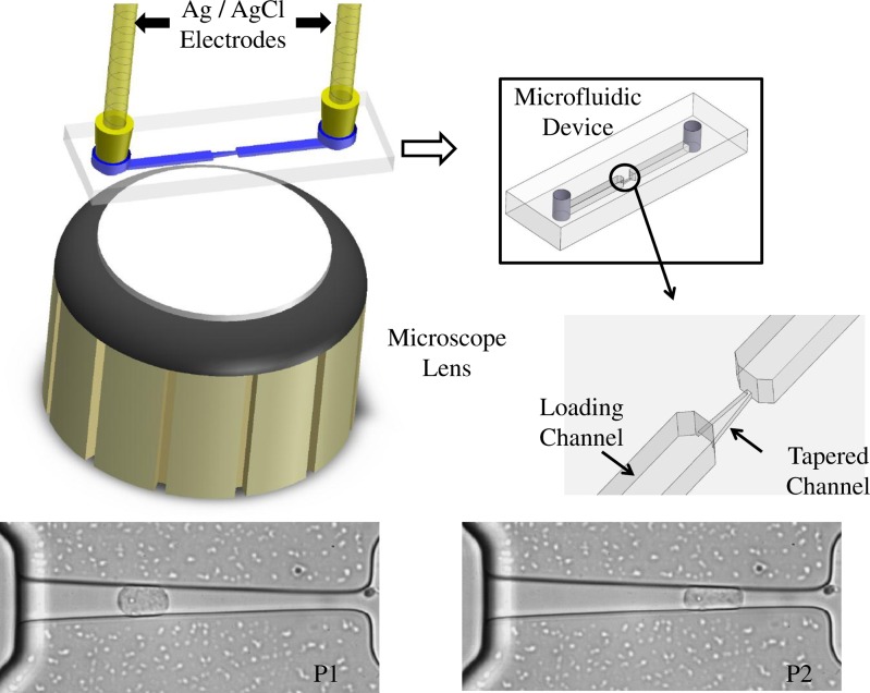
In this paper, we present a microfluidic technique wherein the SMC values of single cells are measured using impedance spectroscopy. A schematic of the microfluidic device is shown in Fig. 1. Compared with previous techniques described above, our device is easier to use and is capable of measuring the full impedance spectrum on a cell within a minute (vs. 10 min/cell as in electro-rotation). An equivalent circuit model is used to fit the impedance spectrum induced by a trapped cell in order to extract its SMC value. Finite element simulations provide theoretical guidance for data interpretation. Impedance and phase data from trapped acute myeloid leukemia (AML2) cells in various osmotic environments are recorded and analyzed. In addition, two types of leukemia cell lines (AML2 and NB4) are shown to be distinguishable based on their SMC differences.
Figure 1.
Schematic of the experimental apparatus. Silver/silver chloride electrodes are inserted into inlet and outlet ports for impedance measurements. In parallel with the electrodes are fluid-filled tubes that route cells into the inlet port, through the loading channel, and finally into the tapered channel. Screen captures of an AML2 cell illustrate its shape changes at two different positions (P1 and P2). Cells are pressurized using a custom pumping system.44
MATERIALS AND METHODS
Materials
All chemicals used in experiments were obtained from Sigma-Aldrich (Oakville, ON, Canada). Cell-culture reagents were purchased from the American Type Culture Collection (ATCC, Manassas, VA, USA). Materials used for device fabrication include SU-8 photoresist (MicroChem Corp., Newton, MA, USA) and 184 silicone elastomer (Ellsworth Adhesives Canada, Burlington, ON, Canada).
Acute myeloid leukemia cell lines (AML2 (Refs. 45, 46) and NB4 (Ref. 47)) are cultured in Dulbecco’s Modified Eagle’s Medium (DMEM) supplemented with 10% fetal bovine serum and 1% penicillin (medium conductivity = 1.5 S/m). Before harvest, cells are incubated at 37 °C in a humidified 5% CO2 atmosphere for 2 days in a 25 ml culture flask. At harvest, we gently tap the culture flasks to suspend the cells.
Experimental procedures
To investigate osmotic effects, AML2 cells are suspended in isotonic (269 mOsm/kg), marginally-hypertonic (344 mOsm/kg), and very-hypertonic (489 mOsm/kg) solutions.48 The corresponding solution conductivities, as measured using a digital conductivity meter (Eutech Instruments), are 1.24, 1.30, and 1.30 S/m, respectively. Hypertonic solutions are made by mixing cell suspensions with a sucrose/dextrose solution in a 1:4 ratio, and isotonic solutions are made by mixing cell suspensions with distilled water in a 1:3 ratio. Before each measurement, cells are incubated in the sucrose/dextrose solution for 15 min. This allows the cell adequate time to equilibrate with the new osmotic condition. To compare the SMC values of AML2 and NB4 cells, both cell lines are suspended in DMEM during experiments.
Microfluidic devices are fabricated according to standard soft lithography procedures as outlined in an earlier work.49 After preloading the microfluidic channel with an appropriate extracellular medium, a droplet of dilute cell suspension is delivered into the microfluidic device. Before a cell is aspirated into the tapered channel, a reference impedance spectrum is collected using Ag/AgCl electrodes located at the inlet and outlet ports. The Ag/AgCl electrodes are specifically chosen to reduce the secondary impedance contributions from the electrical double layer bridging the electrode and electrolyte.50 The impedance spectrum is recorded using an impedance analyzer (Agilent 4292A). Cells are then guided into the loading channel using negative pressure (−100 Pa), and a single cell is drawn inside the tapered channel. Maintaining a small negative pressure (−50 Pa) afterward establishes a good seal between the trapped cell and the channel walls. While recording the impedance spectrum of the cell, microscope imaging (Nikon eclipse Te2000-S) is used for observing and recording videos of the cell shape inside the tapered channel.
To test the device repeatability, we record the impedance spectra induced by a cell parked at two different positions in the tapered channel. After recording the cell impedance spectrum at the first position, we apply a larger negative pressure (−70 Pa) to aspirate the cell into a more constrictive region of the tapered channel. After recording the second cell impedance spectrum, we apply a −100 Pa pressure to aspirate the cell fully through the tapered channel. This procedure is repeated sequentially for all cells.
Equivalent circuit models and curve fitting
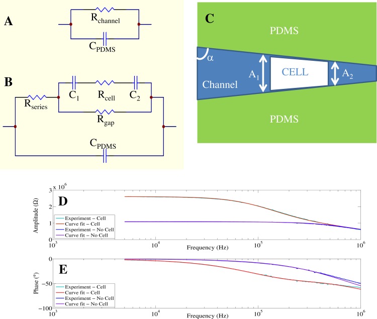
We devised equivalent circuit models to quantify the impedance behaviour of the microfluidic device when the tapered channel is unplugged, and then plugged with a single cell (Figs. 2a, 2b). A nonlinear least-squares curve fitting algorithm is employed in a matlab program to fit the measured impedance to the devised equivalent circuit models (Figs. 2a, 2b).
Figure 2.
(a) and (b): Circuit models used for fitting the impedance and phase spectra generated by an empty channel (a), and a single cell trapped in the channel (b). A membrane-bound cell has a cytoplasmic resistance, Rcell, and a membrane capacitance, Cm = C1C2/(C1 + C2). To account for space between the cell perimeter and the channel walls, a seal resistance, Rgap, is introduced. Experimental amplitude (d) and phase (e) spectra of one measured cell are fitted with the circuit models in (a) and (b).
When the tapered channel is unplugged (Fig. 2a), the impedance is described by a parallel RC circuit where Rchannel represents the channel resistance and CPDMS represents the capacitance of the channel and surroundings (polydimethylsiloxane (PDMS), air, glass).7, 21, 37, 42, 51
When the tapered channel is plugged (Fig. 2b), it contains impedance contributions from both the extracellular fluid and the trapped cell. The latter can be modelled as a resistive cytoplasm, Rcell, in series with a capacitive plasma membrane. The cell surface areas facing the channel inlet and outlet are approximated as two capacitors in series, C1 and C2. Current in the tapered channel is split between entering the plasma membrane and the shunt pathway between the cell and channel walls. Consequently, a gap resistance, Rgap, represents the resistance of the shunt current path.7, 37, 51
To reduce the parameters in our circuit model and increase the curve-fitting accuracy, the following procedures are used. The channel resistance (Rchannel) and capacitance (CPDMS) are determined by curve-fitting the impedance spectrum from a fluid-filled channel without a cell present.
-
(a)After a cell is aspirated in the tapered channel, its volume replaces an equal volume of extracellular fluid. Consequently, the resistance contributed by extracellular fluid in the channel decreases. Equation 1 is used to calculate the resistance loss due to cell trapping (Rloss). Therefore, when a cell is trapped, the remaining channel resistance is calculated using . The channel conductivity and height are and h, respectively. The cell widths facing the channel inlet and outlet are and , respectively, and α is the angle between a channel wall and the horizontal axis (Fig. 2c)
(1) -
(b)
Rgap is the seal resistance. It is determined using the low frequency impedance value obtained from the trapped cell impedance spectrum to subtract the Rseries value.
-
(c)
Finally, the total membrane capacitance, Cm, and cytoplasm resistance, Rcell, are extracted after curve-fitting the impedance spectrum induced by a trapped cell.
A regression coefficient ρ quantifies the degree to which the derived parameters fit the measurement data. Xest (fi) values are estimated from the devised equivalent circuit model, while Xexp (fi) are experimental data. A value of ρ close to 1 means a good fit between the theoretical model and the experimental data2
| (2) |
Determination of specific membrane capacitance
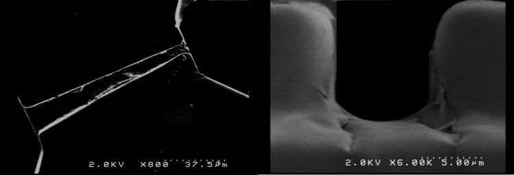
Once the membrane capacitance (C) is extracted, we calculate the cross-sectional membrane areas (A) to calculate the specific membrane capacitance, . Using video microscopy, we observe that a single cell trapped in the tapered channel forms intimate contacts with the channel walls. Therefore, the exposed membrane surface areas are approximated to be the cross-sectional areas of the tapered channel (extracted from SEM imaging, shown in Fig. 3) at the proximal and distal ends of the cell at its trapped position (see Fig. 2c).
Figure 3.
SEM images of the tapered channel: (a) top-view and (b) view through the cross-section.
SIMULATION
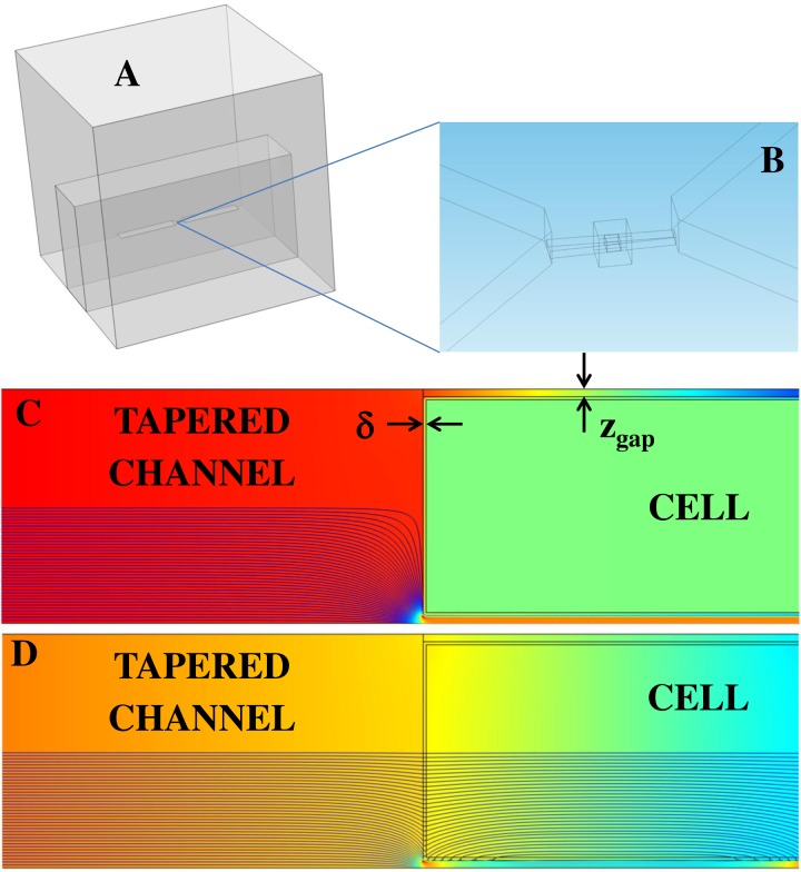
To demonstrate the feasibility of this approach, a three-dimensional model of the microfluidic device is built using comsol multiphysics 4.2 (Fig. 4a). The 3D model comprises the experimental channel dimensions. A zoomed-in portion of the tapered channel is shown for clarity (Fig. 4b). The gap distance, zgap, is taken as the vertical distance between the cell perimeter and a channel wall.
Figure 4.
(a) Three-dimensional geometry of the microfluidic chip. (b) A moderately sized box surrounding the cell and channel facilitated meshing between the large PDMS domain and the much smaller channel domain. (c) and (d) For illustrative purposes, a side view of the microfluidic channel reveals lines of current density coloured according to their strength (blue= weak, red = strong). Similarly, the background colour represents electric potential. In this demonstration, the membrane thickness, δ, is 100 nm and zgap = 250 nm. At low frequencies (Fig. 4c–4 kHz), current is redirected through the shunt pathways (zgap). At high frequencies (Fig. 4d–1 MHz), current is permitted through the cell.
Due to Maxwell-Wagner interfacial polarization, the extent to which an electrically heterogeneous cell stores and conducts electrical charge depends on frequency. As shown in Figs. 4c, 4d, the insulating membrane redirects current toward the conductive shunt pathway at low frequencies (4 kHz) and permits current flow at higher frequencies (1 MHz).
Before aspiration, the cell is assumed to be a single-shelled sphere. Consequently, we use a single-shell model to evaluate the effective permittivity and conductivity of the sphere. In the 3D simulation results that follow, we model the cell as a trapezoidal block (conforming to the local channel geometry minus a gap distance) having a complex effective permittivity, , given by
| (3) |
where (outer radius/inner radius) and the complex permittivities of the cytoplasm and membrane are and , respectively. From this, the frequency-dependent permittivity and conductivity of the cell are and , respectively.52
Terminal electrodes are placed at the far ends of the channel geometry. We solve the Laplace equation for the potentials (V) and electric fields () between the terminals in the frequency domain. By assigning a fixed voltage across the terminals, comsol solves for the admittance, the reciprocal of which is the impedance, Z. The corresponding phase is .
RESULTS AND DISCUSSION
Simulation results
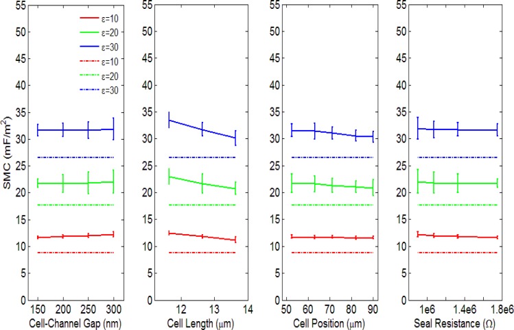
A single cell trapped inside the tapered channel has a specific length, position, and gap distance between its perimeter and the channel wall. To investigate the dependence of these parameters on the determined SMC, we measure the impedance responses from a simulated three-dimensional channel geometry using finite element analysis. Variations due to a single parameter (e.g., cell length) are effectively isolated by keeping the two remaining parameters constant. In each simulation set, we vary the relative permittivity of the membrane (10, 20, and 30) while keeping the membrane thickness constant (10 nm). In this way, we tabulate theoretical SMC values using (Table TABLE I.). For comparison, the simulated impedance and phase spectra are recorded and curve-fitted using the procedures described in Secs. 2C, 2D to extract the SMC values using the equivalent circuit model. All the curve-fitted results have a ρ value larger than 0.99.
TABLE I.
SMC values and variations versus membrane permittivity. For three relative membrane permittivities (10, 20, 30), the theoretical (based on parallel-plate (p.p.) capacitance formula) and curve-fitted SMC values (units are mF/m2) are evaluated as a function of cell-to-channel gap, cell length, cell position and seal resistance. The error ranges correspond to the fitted SMC variations across the gap, length, position, and seal resistance ranges in Fig. 5.
| Relative permittivity | SMC (p.p.) | SMC vs. Gap | SMC vs. Length | SMC vs. Position | SMC vs. Seal resistance | Mean SMC |
|---|---|---|---|---|---|---|
| 10 | 8.85 | 11.9 ± 0.2 | 11.8 ± 0.5 | 11.66 ± 0.08 | 11.9 ± 0.2 | 11.8 ± 0.3 |
| 20 | 17.70 | 21.8 ± 0.2 | 21.8 ± 0.9 | 21.3 ± 0.3 | 21.8 ± 0.2 | 21.6 ± 0.6 |
| 30 | 26.55 | 31.7 ± 0.1 | 32 ± 2 | 31.0 ± 0.5 | 31.7 ± 0.1 | 31.4 ± 0.8 |
Nonlinear regression analyses were applied to determine the uncertainties of the least-squares (best-fit) coefficient of the membrane capacitance. The SMC values were derived by dividing the membrane capacitance with the corresponding cross-section area of the modeled cell. The theoretical SMC values along with the derived SMC values vs. cell position, length, gap distances, and seal resistance are shown in Fig. 5. The dashed lines represent the theoretical SMC values, while the solid lines represent the SMC values derived from curve fitting. The error bars represent the 95% confidence intervals for the SMC.53
Figure 5.
Specific membrane capacitances versus cell-to-channel gap, cell length, cell position and seal resistance. The error bars represent the 95% confidence intervals for the fitted SMC.
When the relative permittivity of the cell increases (10, 20, and 30), the derived SMC correspondingly increases (11.8 ± 0.3 mF/m2, 21.6 ± 0.6 mF/m2, and 31.4 ± 0.8 mF/m2, the error ranges here represent the variation of the fitted SMC variation across the cell-channel gap, cell length, cell position, and seal resistance ranges), giving a ratio close to 1:2:3. For the parametric simulation, the range of cell lengths was chosen based on the minimum and maximum cell sizes observed from imaging in experiments (11.6 μm–13.6 μm). The range of cell positions was chosen from a typical range of positions observed in experiments (52.6 μm–90.0 μm) relative to the tapered channel inlet. Finally, since the low-frequency impedance has a strong dependence on the gap distance, the range of gap distances (150 nm–300 nm) was chosen using simulated impedance spectra that have comparable low-frequency values to those in experimental impedance spectra.
Results shown in Fig. 5 suggest that the derived SMC values do not significantly vary with cell length, position, or gap distance. A maximum variance of ± 2 mF/m2 occurs vs. cell length for the case (6.25% of the mean value). In addition, since the cell volume changes as each parameter varies, we claim that the SMC value obtained from curve-fitting is a size-independent parameter reflecting the electrical properties of the plasma membrane. However, the curve-fitted SMC values are generally larger than the theoretical values. Based on the device design, we believe there are three possible reasons for these differences:
-
(1)
The channel resistance, Rchannel, is calculated based on Ohm’s law for defining resistance, i.e., , which assumes a uniform current distribution inside the channel. However, sharp geometric transitions in the microfluidic device induce the bending of current lines, which breaks down this assumption. In our device, such geometric variations occur at the loading-to-tapered channel interfaces, and at the exposed cross-sectional areas of the cell (current shunt pathway). The current distributions at these interfaces are generally non-uniform and frequency dependent (Figs. 4c, 4d).
-
(2)
In the simulation, we apply the single-shell sphere model to define the effective permittivity and conductivity of the cell. Given that the sphere conforms more toward a trapezoidal shape in the tapered channel, the directional nature of the permittivity in the non-symmetric shape may play a role in determining the SMC. Indeed, the maximum SMC variations arise from changes in cell length, which would cause the cell to deviate progressively more or less from spherical symmetry. Variations in the effective permittivity due to geometric considerations may alter the membrane permittivity and hence the specific membrane capacitance.
-
(3)
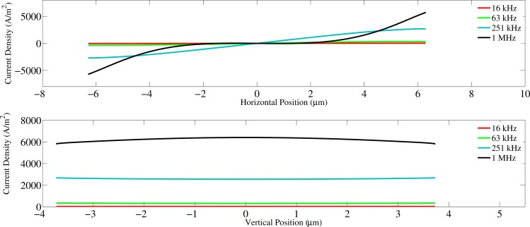
As the frequency of the excitation signal increases, current lines begin to penetrate the cell perimeter sections that are parallel to the channel wall. Consequently, these horizontally-aligned membrane sections may also contribute to the capacitance (Figs. 4c, 4d). When this occurs, the real surface area involved as a capacitor in the circuit is effectively larger than the assumed surface area (vertical membrane sections) used to calculate the SMC. Consequently, our underestimation of the membrane area may yield a SMC value that is larger than expected. (Fig. 6).
Figure 6.
Current density versus position along the horizontal and vertical edges of the membrane.
Due to the reasons above, the curve-fitted SMC values are larger than the SMC values calculated using the parallel-plate capacitance formula. Notwithstanding this upward shift, our simulation has revealed a clear relationship between membrane permittivity and the curve-fitted capacitance, which is not affected by variations in cell volume. Hence, the SMC values determined from experimental data and curve-fitting reflect the cell membrane’s electrical property.
Experimental results
It is well known that the cell membrane acts as an efficient insulator in the low frequency range (5 kHz–100 kHz). Thus, in our device, current is forced to flow around the cell. Because of the intimate cell/channel wall contact, the gap existing in between forms a very good seal which lead to a relatively large resistance, thus a stable impedance plateau can be seen at the low frequency range for the trapped cell impedance profile (Fig. 2d). In this case, more of the cell/channel interaction rather than the cell property are revealed. As the frequency increases (100 kHz–1 MHz), current flow across the cell membrane becomes more and more efficient. Since the voltage applied is constant, the total current would increase inside the constriction channel. In this case, both cell membrane and cytoplasm electrical property are reflected.
A large seal resistance is important for cell membrane capacitance quantification.39, 51 When a cell is trapped inside the tapered channel, the continuously applied negative pressure would drag the cell membrane close to the channel wall, creating a good seal. The low frequency impedance amplitude measured at this moment is mostly contributed by the seal resistance Rgap and the channel resistance Rseries (Fig. 2b). The plateau in the low frequency range (5 kHz–10 kHz) of the amplitude spectrum reveals the sealing quality (Fig. 2d).
Experimentally, the smallest and the largest seal resistance values were 0.7 MΩ and 2.4 MΩ. The reason for this range of seal resistance values was due to the variation of cell size. In general, larger cells created a better seal resistance than smaller cells. Cells were placed at two different positions inside the tapered channel, and SMC values derived at the two different positions will be compared later in the paper.
In this section, we present results from two experiments. Through variations in the SMC, the first experiment evaluates the response of AML2 cells to osmotic variations, and the second experiment evaluates the differences between two leukemia cell lines having differing levels of metastatic potential. In both experiments, we monitor the cellular integrity both by imaging and through impedance measurement. When the cellular integrity is compromised, we observe the ejection of cytoplasmic contents from the cell. At the same time, the low-frequency impedance dramatically decreases and no plateau is formed. For all recorded data shown in Fig. 7, cell integrity is preserved as cells are drawn further into the tapered channel. Consequently, the membrane properties are expected to remain unchanged during cell aspiration and were confirmed by the constant SMC determined in experiments.
Figure 7.
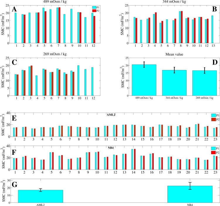
(a)-(d): Specific membrane capacitance (SMC) values for cells in solutions of different osmolalities. Cells in isotonic or marginally hypertonic solutions yield essentially identical SMC values (), while very-hypertonic solutions induced significant increase () in the SMC. (e)-(g): Specific membrane capacitance values of 23 AML2 and 23 NB4 cells in DMEM. Based on the SMC distributions across each cell population, the mean SMC values of AML2 and NB4 cells are found to be significantly different (). Cells initially parked at a position, P1, are later parked at a more constrictive position, P2.
AML2 in different osmolality solutions
AML2 cells exposed to different osmotic conditions were measured. Cells immersed in hypertonic solutions experienced volume shrinkage compared with cells near or within the optimal isotonic range (260–320 mOsm/kg).48 The corresponding cell diameters for cells in isotonic, marginally-hypertonic, and very-hypertonic solutions are 11.1 ± 0.6 μm (n = 12), 10.6 ± 0.8 μm (n = 13), and 9.6 ± 0.7 μm (n = 12), respectively. Cells immersed in very-hypertonic solutions also produce significantly larger () SMC values than cells in isotonic or marginally hypertonic solutions. The SMC values produced by isotonic, marginally hypertonic, and very-hypertonic solutions are 16.6 ± 1.9 mF/m2, 16.8 ± 1.9 mF/m2, and 20.5 ± 1.8 mF/m2, respectively (Fig. 7d).
In order to test the repeatability of the device and technique, impedance profiles were recorded at two positions for each cell. Cells measured at two different positions (P1 and P2) in the tapered channel are found to generate similar SMC values (Figs. 7a, 7b, 7c, 7d). As the cell moved from P1 to P2, it elongated and formed a more intimate seal with the channel wall. However, as previously confirmed by simulation, the SMC value does not significantly vary with cell length, position, or gap distance. Therefore, the SMC variations of the cell population are likely due to heterogeneity among the cells. Occasionally, when a cell was aspirated into position P2, it began to slip through the channel before the impedance spectrum was fully recorded. When this happened, we only plotted data from P1.
Several previous studies independently confirmed that changes in surface morphology are primarily responsible for SMC variations in different osmotic conditions.2, 54, 55 This phenomenon is evident in our measurement results for AML2 cells immersed in different osmotic solutions (Figs. 7a, 7b, 7c, 7d). In human blood plasma, cells normally present a wide tolerance range (optimally, 260–320 mOsm/kg) to osmotic pressure.48 Within the optimal tolerance range, the cell morphology is not expected to vary significantly and indeed, the SMC varies insignificantly (p = 0.34) for cells in 269 and 344 mOsm/kg solutions. However, cells immersed in a solution having an osmolality (489 mOsm/kg) that is well outside the optimal tolerance range reveal significantly higher SMC values (). Rich et al. note that the cell surface area generally remains constant over a wide range of volume swelling and shrinking. Consequently, very hypertonic solutions that cause cell volume shrinkage correspondingly initiate membrane rippling.56 Irimajiri et al. found that cell volume shrinkage in hypertonic solutions can also induce the microvilli to increase in thickness and elongation. Essentially, cells immersed in hypertonic extracellular media undergo severe volume shrinkage, which leads to local cell membrane folding and surface area enhancement that produces larger SMC values.54
AML2 vs. NB4
Acute myeloid leukemia (AML) is characterized by the rapid growth of abnormal white blood cells, which accumulate in the bone marrow and interfere with normal blood cell production.45 Acute promyelocytic leukemia (APL) is a subtype of AML, which is characterized by a chromosomal translocation involving the retinoic acid receptor-alpha gene on chromosome 17 (RARα).47 Since APL cells are known to have a higher metastatic potential than AML cells, we investigated how the corresponding SMC values vary between these cell lines.57 For this experiment, we characterized AML2 (AML cell line) and NB4 (APL cell line) cells. Each cell was measured at two different positions in the tapered channel.
The SMC values for AML2 and NB4 cell lines are distinguishable () at 16.9 ± 1.9 mF/m2 (n = 23) and 22.5 ± 4.7 mF/m2 (n = 23), respectively. In addition, similar SMC values are extracted from cells located at positions P1 and P2. Therefore, the membrane property for each individual cell is considered to remain constant during each cell measurement at P1 and P2 (Figs. 7e, 7f, 7g). Osmolality measurements performed in this study show that our methodology has the potential to extract SMC and correlate it with cell surface morphology. APL cells are known to contain more membrane proteome than AML cells, which may suggest that additional membrane proteome increases the surface complexity of NB4 cells.57 Compared to AML2 cells, the larger SMC values and variations of NB4 cells can be due to their more complex membrane morphologies and suggest that NB4 cells could also have more heterogeneity across their population.
CONCLUSIONS
This paper presented a microfluidic device that performs SMC measurements of single cells using impedance spectroscopy. Three-dimensional impedance simulation confirms the validity of the equivalent circuit model. Based on the impedance and phase traces from experimental and simulated geometries, we demonstrated that AML2 and NB4 cells are distinguishable based on their SMC values. Additionally, compared with immersion in isotonic solutions, immersion of AML2 cells in hypertonic solutions caused volume shrinkage, leading to a relative decrease in the mean SMC. The technique is easy to use and has a testing speed of approximately 1 min/cell.
ACKNOWLEDGMENTS
The authors thank Dr. David Dubins from the Pharmaceutics Laboratory at the University of Toronto for providing access to a vapor pressure deposition osmometer. The authors thank the staff of the Emerging Communications Technology Institute (ECTI) for microfabrication assistance. Financial support from the Natural Sciences and Engineering Research Council of Canada (NSERC) through a Strategic Grant and the Canada Research Chairs Program is also acknowledged.
References
- Iyer S., Gaikwad R. M., Subba Rao V., Woodworth C. D., and Sokolov I., Nat Nanotechnol. 4(6), 389–393 (2009). 10.1038/nnano.2009.77 [DOI] [PMC free article] [PubMed] [Google Scholar]
- Wang X.-B., Huang Y., Gascoyne P. R. C., Becker F. F., Hölzel R., and Pethig R., Biochim. Biophys. Acta, Biomembr. 1193(2), 330–344 (1994). 10.1016/0005-2736(94)90170-8 [DOI] [PubMed] [Google Scholar]
- Wang X., Becker F. F., and Gascoyne P. R. C., Chaos 20(4), 043133–043137 (2010). 10.1063/1.3526972 [DOI] [PMC free article] [PubMed] [Google Scholar]
- Arnold W. M. and Zimmermann U., Z. Naturforsch. C 37(10), 908–915 (1982). [Google Scholar]
- Arnold W. M. and Zimmermann U., J. Electrostat. 21(2–3), 151–191 (1988). 10.1016/0304-3886(88)90027-7 [DOI] [Google Scholar]
- Gross L. C. M., Heron A. J., Baca S. C., and Wallace M. I., Langmuir 27(23), 14335–14342 (2011). 10.1021/la203081v [DOI] [PubMed] [Google Scholar]
- Bao J. Z., Davis C. C., and Schmukler R. E., Biophys. J. 61(5), 1427–1434 (1992). 10.1016/S0006-3495(92)81948-3 [DOI] [PMC free article] [PubMed] [Google Scholar]
- Long Q. and Xing W., Front Biol China 1(2), 208–212 (2006). 10.1007/s11515-006-0010-2 [DOI] [Google Scholar]
- Minerick A. R., Zhou R., Takhistov P., and Chang H.-C., Electrophoresis 24(21), 3703–3717 (2003). 10.1002/elps.200305644 [DOI] [PubMed] [Google Scholar]
- Gordon J. E., Gagnon Z., and Chang H. C., Biomicrofluidics 1(4), 44102 (2007). 10.1063/1.2818767 [DOI] [PMC free article] [PubMed] [Google Scholar]
- Kuczenski R. S., Chang H.-C., and Revzin A., Biomicrofluidics 5(3), 032005–032015 (2011). 10.1063/1.3608135 [DOI] [PMC free article] [PubMed] [Google Scholar]
- Pethig R., Biomicrofluidics 4(2), 022811–022835 (2010). 10.1063/1.3456626 [DOI] [PMC free article] [PubMed] [Google Scholar]
- Wu L., Yung L.-Y. L., and Lim K.-M., Biomicrofluidics 6(1), 014113–014110 (2012). 10.1063/1.3690470 [DOI] [PMC free article] [PubMed] [Google Scholar]
- Teixeira-Pinto A. A., L. L.Nejelski, Jr., Cutler J. L., and Heller J. H., Exp. Cell Res. 20(3), 548–564 (1960). 10.1016/0014-4827(60)90123-3 [DOI] [Google Scholar]
- Zhou X.-F., Markx G. H., Pethig R., and Eastwood I. M., Biochim. Biophys. Acta, Gen. Subj. 1245(1), 85–93 (1995). 10.1016/0304-4165(95)00072-J [DOI] [PubMed] [Google Scholar]
- Neher E. and Sakmann B., Nature 260(5554), 799–802 (1976). 10.1038/260799a0 [DOI] [PubMed] [Google Scholar]
- Chen C. and Folch A., Lab Chip 6(10), 1338–1345 (2006). 10.1039/b607913j [DOI] [PubMed] [Google Scholar]
- Hamill O. P., Marty A., Neher E., Sakmann B., and Sigworth F. J., Pflugers Arch. 391(2), 85–100 (1981). 10.1007/BF00656997 [DOI] [PubMed] [Google Scholar]
- Ionescu-Zanetti C., Shaw R. M., Seo J., Jan Y.-N., Jan L. Y., and Lee L. P., Proc. Natl. Acad. Sci. U. S. A. 102(26), 9112–9117 (2005). 10.1073/pnas.0503418102 [DOI] [PMC free article] [PubMed] [Google Scholar]
- Klemic K. G., Klemic J. F., Reed M. A., and Sigworth F. J., Biosens. Bioelectron. 17(6–7), 597–604 (2002). 10.1016/S0956-5663(02)00015-5 [DOI] [PubMed] [Google Scholar]
- Li S. and Lin L., Sens. Actuators, A 134(1), 20–26 (2007). 10.1016/j.sna.2006.04.034 [DOI] [Google Scholar]
- Matthews B. and Judy J. W., J. Microelectromech. Syst. 15(1), 214–222 (2006). 10.1109/JMEMS.2005.863606 [DOI] [Google Scholar]
- Ong W.-L., Kee J.-S., Ajay A., Ranganathan N., Tang K.-C., and Yobas L., Appl. Phys. Lett. 89(9), 093902–093903 (2006). 10.1063/1.2336213 [DOI] [Google Scholar]
- Dalton C., Goater A. D., Burt J. P. H., and Smith H. V., J. Appl. Microbiol. 96(1), 24–32 (2004). 10.1046/j.1365-2672.2003.02113.x [DOI] [PubMed] [Google Scholar]
- Yang J., Huang Y., Wang X., Wang X.-B., Becker F. F., and Gascoyne P. R. C., Biophys. J. 76(6), 3307–3314 (1999). 10.1016/S0006-3495(99)77483-7 [DOI] [PMC free article] [PubMed] [Google Scholar]
- Zhou X. F., Burt J. P. H., and Pethig R., Phys. Med. Biol. 43(5), 1075 (1998). 10.1088/0031-9155/43/5/003 [DOI] [PubMed] [Google Scholar]
- Sjoblom J., Feldman Y., and Skodvin T., in Encyclopedic Handbook of Emulsion Technology (CRC, 2001), pp. 109–168. [Google Scholar]
- De Gasperis G., XiaoBo W., Jun Y., Frederick F. B., and Peter R. C. G., Meas. Sci. Technol. 9(3), 518 (1998). 10.1088/0957-0233/9/3/029 [DOI] [Google Scholar]
- Hughes M. P., Wang X.-B., Becker F. F., Gascoyne P. R. C., and Pethig R., J. Phys. D: Appl. Phys. 27(7), 1564 (1994). 10.1088/0022-3727/27/7/035 [DOI] [Google Scholar]
- Hughes M. P., Archer S., and Morgan H., J. Phys. D: Appl. Phys. 32(13), 1548 (1999). 10.1088/0022-3727/32/13/316 [DOI] [Google Scholar]
- Hughes M. P., Phys. Med. Biol. 43(12), 3639 (1998). 10.1088/0031-9155/43/12/019 [DOI] [PubMed] [Google Scholar]
- Holzel R., J. Phys. D: Appl. Phys. 26(12), 2112 (1993). 10.1088/0022-3727/26/12/003 [DOI] [Google Scholar]
- Maswiwat K., Holtappels M., and Gimsa J., Electrochim. Acta 51(24), 5215–5220 (2006). 10.1016/j.electacta.2006.03.048 [DOI] [Google Scholar]
- Sun T., Gawad S., Bernabini C., Green N. G., and Morgan H., Meas. Sci. Technol. 18(9), 2859 (2007). 10.1088/0957-0233/18/9/015 [DOI] [Google Scholar]
- Malleo D., Nevill J. T., Lee L. P., and Morgan H., Microfluid. Nanofluid. 9(2–3), 191–198 (2010). 10.1007/s10404-009-0534-2 [DOI] [PMC free article] [PubMed] [Google Scholar]
- Han A., Yang L., and Frazier A. B., Clin. Cancer Res. 13(1), 139–143 (2007). 10.1158/1078-0432.CCR-06-1346 [DOI] [PubMed] [Google Scholar]
- Bao J. Z., Davis C. C., and Schmukler R. E., IEEE Trans. Biomed. Eng. 40(4), 364–378 (1993). 10.1109/10.222329 [DOI] [PubMed] [Google Scholar]
- Bao N., Zhan Y., and Lu C., Anal. Chem. 80(20), 7714–7719 (2008). 10.1021/ac801060t [DOI] [PubMed] [Google Scholar]
- Chen J., Zheng Y., Tan Q., Shojaei-Baghini E., Zhang Y. L., Li J., Prasad P., You L., Wu X. Y., and Sun Y., Lab Chip 11(18), 3174–3181 (2011). 10.1039/c1lc20473d [DOI] [PubMed] [Google Scholar]
- Di Carlo D. and Lee L. P., Anal. Chem. 78(23), 7918–7925 (2006). 10.1021/ac069490p [DOI] [PubMed] [Google Scholar]
- Holmes D., Pettigrew D., Reccius C. H., Gwyer J. D., van Berkel C., Holloway J., Davies D. E., and Morgan H., Lab Chip 9(20), 2881–2889 (2009). 10.1039/b910053a [DOI] [PubMed] [Google Scholar]
- Morgan H., Sun T., Holmes D., Gawad S., and Green N. G., J. Phys. D: Appl. Phys. 40(1), 61 (2007). 10.1088/0022-3727/40/1/S10 [DOI] [Google Scholar]
- Nikolic-Jaric M., Romanuik S. F., Ferrier G. A., Cabel T., Salimi E., Levin D. B., Bridges G. E. and Thomson D. J., Biomicrofluidics 6 (2), 024117–024115 (2012). 10.1063/1.4709387 [DOI] [PMC free article] [PubMed] [Google Scholar]
- Moscovici M., Chien W. Y., Abdelgawad M., and Sun Y., Biomicrofluidics 4(4), 046501 (2010). 10.1063/1.3499939 [DOI] [PMC free article] [PubMed] [Google Scholar]
- Koistinen P., Siitonen T., Mantymaa P., Saily M., Kinnula V., Savolainen E. R., and Soini Y., Leukemia 15(9), 1433–1441 (2001). 10.1038/sj.leu.2402217 [DOI] [PubMed] [Google Scholar]
- Milella M., Konopleva M., Precupanu C. M., Tabe Y., Ricciardi M. R., Gregorj C., Collins S. J., Carter B. Z., D’Angelo C., Petrucci M. T., Foa R., Cognetti F., Tafuri A., and Andreeff M., Blood 109(5), 2121–2129 (2007). 10.1182/blood-2006-05-024679 [DOI] [PubMed] [Google Scholar]
- Lanotte M., Martin-Thouvenin V., Najman S., Balerini P., Valensi F., and Berger R., Blood 77(5), 1080–1086 (1991). [PubMed] [Google Scholar]
- d. L.Castilho R., Animal Cell Technology: From Biopharmaceuticals to Gene Therapy (Taylor & Francis Group, New York/Abingdon, 2008). [Google Scholar]
- Tan Q., Chen J., Zheng Y., Chen B. K., and Sun Y., presented at the 2012 IEEE 25th International Conference on Micro Electro Mechanical Systems (MEMS), Paris, France, 2012.
- Feder W., J. Appl. Physiol. 18(2), 397–401 (1963). [DOI] [PubMed] [Google Scholar]
- Thein M., Asphahani F., Cheng A., Buckmaster R., Zhang M., and Xu J., Biosens. Bioelectron. 25(8), 1963–1969 (2010). 10.1016/j.bios.2010.01.023 [DOI] [PMC free article] [PubMed] [Google Scholar]
- Jones T. B., Electromechanics of Particles (Cambridge University Press, Cambridge/New York, 1995). [Google Scholar]
- Navidi W. C., Statistics for Engineers and Scientists (McGraw-Hill, Boston/Mass, 2006). [Google Scholar]
- Irimajiri A., Asami K., Ichinowatari T., and Kinoshita Y., Biochim. Biophys. Acta, Biomembr. 896(2), 203–213 (1987). 10.1016/0005-2736(87)90181-7 [DOI] [PubMed] [Google Scholar]
- Zimmermann D., Zhou A., Kiesel M., Feldbauer K., Terpitz U., Haase W., Schneider-Hohendorf T., Bamberg E., and Sukhorukov V. L., Biochem. Biophys. Res. Commun. 369(4), 1022–1026 (2008). 10.1016/j.bbrc.2008.02.153 [DOI] [PubMed] [Google Scholar]
- Rich G. T., Sha’afi I., Romualdez A., and Solomon A. K., J. Gen. Physiol. 52(6), 941–954 (1968). 10.1085/jgp.52.6.941 [DOI] [PMC free article] [PubMed] [Google Scholar]
- Hofmann A., Gerrits B., Schmidt A., Bock T., Bausch-Fluck D., Aebersold R., and Wollscheid B., Blood 116(13), E26–E34 (2010). 10.1182/blood-2010-02-271270 [DOI] [PubMed] [Google Scholar]


