Abstract
Current trends in photonic crystal microcavity biosensors in silicon-on-insulator (SOI), that focus on small and smaller sensors have faced a bottleneck trying to balance two contradictory requirements of resonance quality factor and sensitivity. By simultaneous control of the radiation loss and optical mode volumes, we show that both requirements can be satisfied simultaneously. Microcavity sensors are designed in which resonances show highest Q ~9,300 in the bio-ambient phosphate buffered saline (PBS) as well as highest sensitivity among photonic crystal biosensors. We experimentally demonstrated mass sensitivity 8.8 atto-grams with sensitivity per unit area of 0.8 picograms/mm2 Highest sensitivity, irrespective of the dissociation constant Kd, is demonstrated among all existing label-free optical biosensors in silicon at the concentration of 0.1μg/ml.
Keywords: photonic crystal microcavity, biosensor, nanophotonic biosensor
1. Introduction
In recent years, significant research has focused on demonstrating on-chip microarrays for diagnostic assays in diverse fields of science and technology (Iqbal et al, 2010; Densmore et al, 2009; Sipova et al., 2010). Label-free assays are particularly exciting since they avoid both the complex chemistries caused by steric hindrance as well as the costs associated with labeling. The assay detects the specific binding between the target receptor biomolecules functionalized on a suitable substrate with probe biomolecules in the sample solution. The binding event is then transduced via optical, electrical, mechanical or magnetic means to name a few. Optical detection techniques are generally attractive due to their freedom from electromagnetic interference.
While several platforms based on ring resonators (Iqbal et al, 2010), wire waveguides (Densmore et al, 2009) and surface plasmon resonance (SPR) (Sipova et al., 2010) have been investigated in recent years, photonic crystal (PC) (Chakravarty et al, 2005; Lai et al, 2012), in general, are more compact (of the order of a few square microns in surface area) and promise the potential for higher sensitivity than other devices. Since the first demonstration of biosensors on the photonic crystal platform (Lee et al., 2007), various groups have performed research with different photonic crystal sensor architectures (Lee et al., 2007; Kang et al., 2007; Mandal et al., 2008; Scullion et al., 2011; Dorfner et al, 2009; Zlatanovic et al., 2009), with the goal to demonstrate the highest sensitivity. A quick survey of the literature shows that research groups have used different biomolecule conjugates of target receptor biomolecules and probe biomolecules, for sensing experiments. Comparisons of sensitivity have been drawn based on the minimum mass sensing capabilities of different sensing platforms (Scullion et al., 2011). However, binding kinetics between the target receptor biomolecules and probe biomolecules in solution, also determines the sensitivity of photonic crystal biosensors. In addition, the focus has been primarily to develop the smallest sensor. Researchers have thus tried to balance two contradictory requirements of sensitivity and quality factor. However, any attempt to reduce the resonator size or increase the optical mode overlap with the analyte leads to a reduction in resonance quality factor and hence the ability of the device to detect small concentrations as well as small changes in concentration. An aspect that is overlooked in such hybrid biosensors for microarray applications is that the sensor must be functionalized with receptor/capture biomolecules. When the resonators are patterned via ink-jet printing or microfluidic channels, the receptor/capture biomolecules are actually dispensed over a significantly larger area. Hence, from practical considerations, there is room to achieve both requirements of sensitivity and high Q by engineering designs that are slightly larger than conventional approaches. In this paper, we show that deviating from current trends and slightly increasing the sizes of photonic crystal microcavities can enhance the resonance Q as well enhance the optical mode overlap with the analyte, thereby leading to the highest sensitivity demonstrated in the literature, for different dissociation constants.
2. Materials and Methods
2.1 Device Principles and Fabrication
The total quality factor QT of the resonance mode of a PC microcavity, which is related to the photon lifetime τp, at frequency ω by QT=ωτp is given by
| (1) |
where QR=ωτR and Qi=ωτi, τR and τi represent the radiation loss and intrinsic cavity loss respectively. τR is given by:
| (2) |
where PR denotes the total power radiated by the cavity and WE denotes the stored energy in the cavity which is proportional to the cavity mode volume. Hence a method that reduces PR and increases WE will decrease the radiation loss from the cavity and hence increase the effective Q. A high Q implies that the light is trapped for a longer period of time in the cavity and hence interacts longer with any analyte in the vicinity of the photonic crystal microcavity. In addition, since WE is proportional to the optical mode volume, a higher WE leads to potential for larger optical mode overlap with the analyte which also contributes to higher sensitivity.
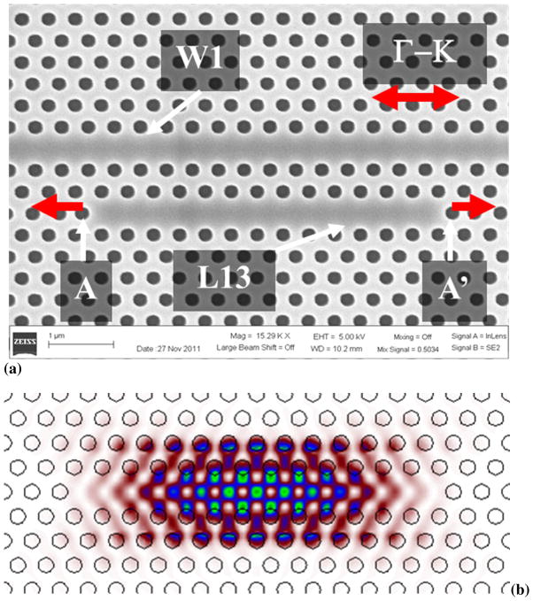
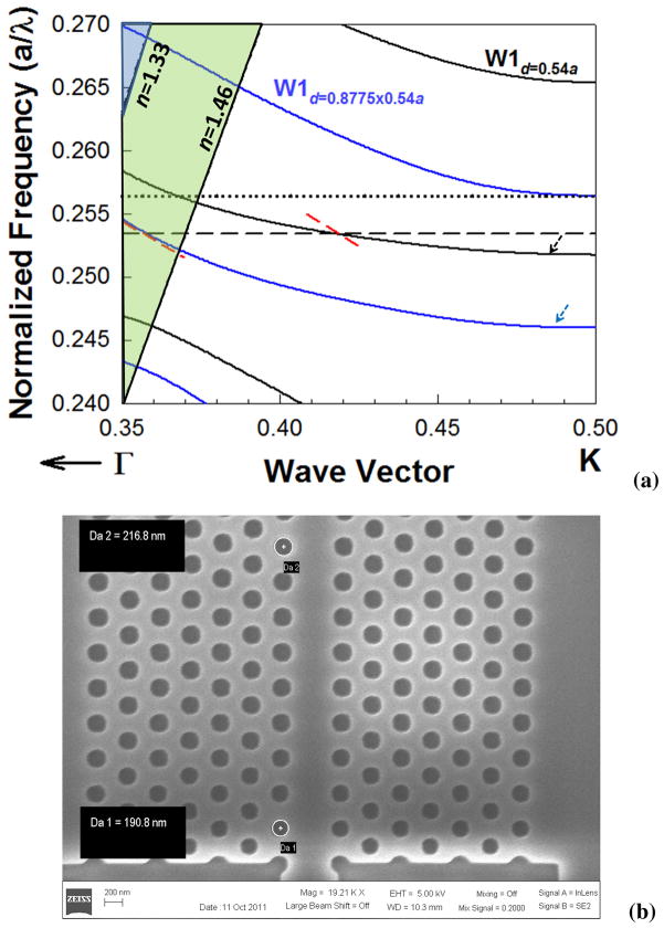
Our photonic crystal (PC) microcavity biosensor consists of a linear photonic crystal microcavity coupled to a photonic crystal waveguide (PCW) in a silicon-on-insulator (SOI) platform. The PCW is a W1 line defect waveguide with uniform lattice constant a=400nm, where W1 denotes that width of the PCW is √3a. Silicon slab thickness and air hole diameter are h=0.58a and d=0.54a. In contrast to conventional devices which study L3 linear PC microcavities, with 3 missing holes along the Γ–K direction (Weiss et al., 2010), or smaller hexagonal microcavities (Lee et al., 2007; Pal et. al., 2011) we study linear L13 PC microcavities with 13 missing holes along Γ–K direction. L13 PC microcavities are fabricated two periods away from the PCW. A scanning electron micrograph image of the same is shown in Fig. 1(a). The edge holes are shifted outward (Akahane et al., 2003) in the Γ–K direction by 0.15a and indicated by A and A′. While the L13 PC microcavity has several resonance modes, the resonance mode profile of interest is shown in Fig. 1(b). The frequency of the resonance mode is indicated by the black dashed line in the dispersion diagram of the W1 PCW by three dimensional plane-wave expansion (PWE) in Fig. 2(a). The dispersion diagram of the W1 PCW is shown by the solid black curves.
Fig. 1.
(a) Scanning electron micrograph image of L13 PC microcavity coupled to W1 PC waveguide. The edge air holes are indicated by A and A′ and the direction of shift indicated by the red arrows. (b) Resonance mode profile of L13 PC microcavity.
Fig. 2.
(a) Dispersion diagram of W1 photonic crystal waveguide for d=0.54a (black curves) and d=0.8775×0.54a (blue curves). The resonance frequency of L13 PC microcavity is shown by black dashed line. The group velocity at the coupling frequency is indicated by the dashed red line. The W1 guided modes are indicated by the black and blue arrows. The black dotted line indicates the upper bound of the radius taper design as determined by the frequency of the higher order mode. (b) SEM image of the input of the photonic crystal waveguide from the ridge waveguide indicating the group index taper.
The higher Q in L13 PC microcavities is due to the combined effects of lower radiation loss as the resonance moves deeper into the photonic band gap compared to L3 PC microcavities (Lai et al, 2012) that are studied conventionally, and the larger mode volume of L13 PC microcavities compared to L3 PC microcavities. Higher Q thus increases the ability to detect small changes in concentration. Furthermore, the slightly increased length enables larger overlap of the optical mode with the analyte leading to higher sensitivity. We have shown (Lai et al., 2012) that increasing the length of the PC microcavities to about 5.5μm in our L13 PC microcavities designed for operation at around 1550nm, from present targets of sub-μm, leads to higher Q and higher sensitivity in chemical sensing. It must be noted here, that in the geometry selected here, the loss from the microcavity into the photonic crystal waveguide also contributes a term QWG to equation 1. A detailed analysis of the effect of QWG and further engineering to compensate for the effect of QWG will be the subject of another paper. In general, QWG is primarily determined by the distance, in terms of number of periods, of the PC microcavity from the PCW as well as the orientation of the PC microcavity with respect to the PCW.
In addition, as the resonance moves deeper into the photonic band gap, the resonance frequencies are located at values closer to the transmission band edge of the W1 PCW where light propagates much slowly compared to the input ridge waveguide. As a result, coupling efficiency between the PC microcavity and the PCW is enhanced as the slow light gets more time to interact with the PC microcavity. However, due to slow light, the group index is effectively enhanced which increases the index mismatch between the PCW and the input ridge waveguide. To lower the resultant effect of Fresnel reflection and optical loss and thus ensure high signal to noise ratio at the resonance wavelengths of the L13 PC microcavity, a gradual group index taper is needed from the ridge waveguide to the PCW. The gradual change in group velocity is achieved by gradually increasing the radius of holes adjacent to the PCW as shown in the SEM image in Fig. 2(b).
At the entrance of the PCW, the diameter d1 of the holes is 0.8775× 0.54a. The dispersion diagram of the W1 PCW with d1=0.8775× 0.54a is indicated by the solid blue curves. As observed from the band structure simulation in Fig. 2(a), this band engineering has the effect of gradually decreasing group velocity vg=δω/δk from the PCW-ridge waveguide entrance to the slow light PCW guiding frequency of the resonant mode as indicated by the slope of the red dashed lines. The choice of d1 is made to ensure that higher order modes do not overlap with the W1 guided mode with d=0.54a as indicated by the black dashed arrow. It has been shown previously (Lin et al., 2010) that such band engineering improves the coupling efficiency at slow light wavelengths.
The device fabrication starts with thorough cleaning of SOI wafers from SOITEC (Peabody, MA), using Piranha clean (H2O2:H2SO4=1:2) for 10 minutes, followed by rinse in deionized (DI) water and drying with nitrogen gun. Starting wafers have a silicon thickness of 250nm. The wafer is next put in a furnace at 950°C for 110minutes to oxidize the silicon so that the final silicon thickness is 230nm. The grown oxide is partially removed by buffered oxide etch (BOE) in 6:1 NH4F (40% in water): HF (49% in water) by volume for 15 seconds. About 20nm of oxide is left to serve as hard mask for photonic crystal pattern etch. The photonic crystal device is then patterned by electron beam (e-beam) lithography using ZEP-520A e-beam resist followed by developing for 2 minutes in developer n-Amyl acetate (ZEP-N50), followed by washing 1 minute in isopropyl alcohol (IPA). The e-beam pattern in resist is next etched into the silicon dioxide by reactive ion etching (RIE) using CHF3 (40sccm)/O2 (3sccm) at 400V DC bias and 40mTorr pressure for 2.5 minutes. Subsequently, the resist is stripped by Remover PG (MicroChem, Newton MA) at 95°C for 10 minutes. The pattern in silicon dioxide is next transferred to silicon by RIE using Cl2 (4sccm)/HBr (25.4sccm) at 250V DC bias at 28mTorr pressure for 4.5 minutes. At the end of the etch, about 10–15nm of silicon dioxide is left behind which is not removed since the silicon dioxide surface can be later functionalized to attach target receptor biomolecules.
2.2. Materials
We selected the following table of target receptor antibody and conjugate probe antibodies for our study. The table also lists the corresponding dissociation constants.
The items we acquired are as follows: Rabbit Anti-Goat IgG (Bio-Rad Labs, Cat. #: 172-1034), Goat Anti-Rabbit IgG (Bio-Rad Labs, Cat. #: 170-6515), Human IL-10 (Insight Genomics, Cat #: RP027), IL-10-rat anti-Human (Invitrogen, Cat #: RHCIL1001), Biotin (Sigma, CAS #: 1405-69-2), Avidin (Sigma, CAS #: 89889-52-1), bovine serum albumin (Invitrogen, Cat #: 15561-020), 3-aminopropyl-triethoxy-silane (3-APTES) (Acros, CAS #:919-30-2), glutaraldehyde (Fischer Scientific, CAS#111-30-8).
2.3 Functionalization
Wafers were functionalized by treating with 10% by volume 3-APTES in toluene. It is then washed 3 times in toluene to remove unbound 3-APTES, 3 times in methanol to remove toluene and finally 3 times in de-ionized water to remove methanol. The wafers are then incubated in 1% glutaraldehyde in phosphate buffered saline (PBS) for 5 minutes and washed 3 times in PBS and ink-jet printed with target antibodies in glycerol. Past research has shown that the 3-APTES-glutaraldehyde coupled layer retains its initial activity for several weeks. (Subramanian et al., 1999) Hence we do not expect any reduction in activity within the 30 minutes by which time the target antibodies are printed. The printed spots were left to incubate overnight. Subsequently, all target antibodies not bound to the functionalized device layer were removed by washing 3 times in PBS. After overnight incubation and washing, the device is coated with bovine serum albumin (BSA) to prevent any non-specific binding and washed 3 times with PBS. The device is now ready for measurements.
2.4 Measurement Method
Light is guided in and out of the PCW by ridge waveguides with PC group index taper to enable high coupling efficiency into the slow light guided mode (Lin et al., 2010). The bottom cladding of silicon dioxide (n=1.46) is kept intact to enable robust devices with high yield. Devices were tested with TE-polarized light by end-fire coupling method with polarization maintaining single mode tapered lensed fiber. All probe antibodies are introduced in PBS which forms the top cladding. When probe antibodies that are specific to their conjugate target antibodies on the different arms are introduced, the conjugate specific binding causes a change in the refractive index in the immediate vicinity of the corresponding PC microcavity leading to a change in resonance frequency and hence a shift in wavelength of the dropped resonance from the transmission spectrum of the PCW.
Before a new addition of probe antibody solution, the resonance wavelength was measured (λ1). For each concentration of newly added probe antibody solution, the chip was incubated in the probe antibody solution and the resonance wavelength monitored as a function of time. No resonance wavelength shift was observed for 20 minutes. After 20 minutes, the resonance wavelength increased as a function of time, until the shift saturated after another 20 minutes at λ2. The chip was next washed 3 times in PBS to remove unbound probe antibodies and the resonance wavelength λ3 (< λ2) measured again. The final resonance wavelength shift Δλ, is plotted later, given by Δλ=λ3−λ1.
2.5 Binding Principle
The binding between a target antibody and its conjugate probe antigen/antibody is governed by the equilibrium equation 3 below. The nomenclature that is followed is that target refers to the receptor biomolecule that is linked to the silicon substrate while probe refers to the biomolecule in the sample solution that will bind specifically to the target if it is the conjugate of the target. Assuming that [P] denotes the concentration of probe biomolecules, [T] denotes the concentration of target antibodies and [PT] denotes the complex formed by the binding of the target biomolecule to the probe biomolecule, the equilibrium equation is given by (Nelson et al., 2008),
| (3) |
The factor which determines whether the reaction proceeds more favorably forward or backward is the dissociation constant (Kd) or its reciprocal, the affinity constant (Ka), according to equation:
| (4) |
Kd is thus a measure to describe the strength of binding (or affinity) between receptors and their ligands. Hence, the amount of probe biomolecules that remain bound to the target biomolecules at any instant of time is larger for a conjugate pair with lower Kd.
The magnitude of binding is determined by De Feijter’s formula (de Feijter et al., 1978) that relates the absolute amount of adsorbed molecules M per unit surface area with the change in refractive index as:
| (5) |
where dA is the thickness of adsorbed layer, nA is the refractive index of adsorbed molecules, nC is the refractive index of cover solution (in this case, the probe biomolecule solution), dc represents the differential change in concentration of adsorbed molecules as a function of distance from the silicon surface, and dn is the differential change in refractive index of adsorbed molecules, also a function of distance from the silicon surface, which is proportional to the shift dλ in position of the resonance peak. The magnitude of resonant wavelength shift is proportional to the amount of adsorbed biomolecules and hence provides a label-free means to quantitatively determine biomolecules of interest.
Since Kd determines how many probe biomolecules and hence the amount of bound probe biomolecule mass to the target receptor biomolecules on the silicon surface, from De Feijter’s equation, the magnitude of resonant wavelength shift is larger for a conjugate pair with lower Kd.
3. Results
The resonance spectrum of the L13 PC microcavity was first measured in PBS, functionalized with target receptor antibodies.
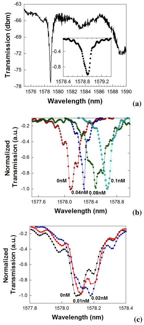
A typical transmission spectrum of the PCW after functionalization, with the coupled L13 PC microcavity is shown in Fig. 3(a). Fig. 3(a) inset magnifies the resonance wavelength range to show the Q~9,300 in these devices in PBS, after functionalization with target receptor antibodies, in the absence of any probe antibodies.
Fig. 3.
(a) Transmission spectrum of W1 PCW with coupled L13 PC microcavity. (Inset) shows the normalized transmission, magnifying the wavelength range around the resonance. Experimental transmission spectra showing the transmission drop resonance spectra for the binding between Avidin to Biotin (Kd~10−15M) (b) between 0nM to 0.1nM and (c) at the lower concentration range between 0nM and 0.02nM.
The resonance wavelength targeted is at 1578nm, near the band edge at 1588nm, with approximately 12dB extinction ratio. Different devices of the same geometry were studied. The resonance frequency indicated in Fig. 3(a) varied in absolute wavelength by at most 1nm due to fabrication imperfections. Fig. 3(b) shows experimental resonant transmission spectra observed when avidin binds to the target biotin. The lowest concentrations are shown separately in Fig. 3(c) for clarity. The shift in the lowest point in the resonance curve is studied. At the lowest concentration of 10pM, a resonance wavelength shift of 0.03nm was observed, as seen distinctly in Fig. 3(c). Our optical spectrum analyzer has a wavelength accuracy of 0.02nm, hence all wavelength shifts greater than 0.02nm are considered as the indication of conjugate biomolecule binding. Fig. 4 plots the resonant wavelength shift Δλ as a function of concentration for each conjugate pair in Table 1 with different Kd. It is observed that the resonant wavelength shift is maximum for the conjugate pair of avidin-biotin, which has the smallest Kd. Furthermore, due to the increased wavelength shift, the device is able to detect concentrations with lower molarity with the conjugate pair of avidin-biotin than the other two pairs.
Fig. 4.
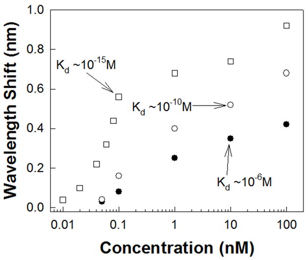
Resonance wavelength shift of the L13 PC microcavity as a function of concentration for various probe-target conjugates in Table 1 as a function of Kd. (filled circles ●) binding of goat anti-rabbit IgG to rabbit anti-goat IgG (Kd ~10−6M); (open circles ○) binding of rat anti-human to Human IL-10 (Kd ~10−10M); (open squares □) binding of avidin to biotin (Kd~10−15M).
Table 1.
Target and Probe Protein conjugates
| Target Protein | Probe Protein | Kd (M), Dissociation Constant |
|---|---|---|
| Rabbit anti-goat IgG | Goat anti-rabbit IgG | ~10−6 (Kuo et al., 1993) |
| Human IL-10 | IL-10, Rat Anti-Human | ~10−9 –10−11 (de Groote et al, 1994) |
| Biotin | Avidin | ~10−15 (Scullion et al., 2011) |
4. Discussions
The resonant wavelength shift is maximum for the conjugate pair of avidin (67kDa)-biotin which has the smallest Kd ~10−15M since equation 2 shows that the denominator is higher when the exponent in Kd is larger. Both rat anti-human IL-10 and goat anti-rabbit IgG antibodies have a molecular weight of 150kDa. Yet, since the human IL-10 to rat anti-human IL-10 Kd ~10−10M compared to the rabbit anti-goat IgG to goat anti-rabbit IgG binding Kd ~10−6M, hence a larger resonant wavelength shift is observed with rat anti-human IL-10 conjugation biochemistry. Q~9,300 represents the highest Q reported for bio-sensing in SOI PC devices. 60μl of probe antibodies was directly dispensed from a micro-pipette. Note that only the probe antibodies are dispensed with the micro-pipette, as in a diagnostic scenario where the sample will be directly dispensed on the microarray chip. The target receptor antibodies were ink-jet printed in-house. In the L13 PC microcavity, (integrating over an area where the E-field intensity is more than 50% of the maximum value and including the entire internal surface area of the holes along the periphery of the photonic crystal microcavity in the Γ–K orientation where the E-field intensity is more than 50% over a fraction of the periphery of the hole) (Dorfner et al, 2009), from Fig. 1(b), the optical mode overlaps a surface area on the chip of 11μm2. The actual real estate coverage on the chip is 5.7μm2. Since the probe Ab of volume 60μl when dispensed covers a diameter of 8mm and assuming uniform surface coverage, the experimentally detected mass in L13 devices is 8.8 atto-grams (1 atto-gram = 10−18grams). In terms of surface density, for avidin detection, the above mass detection limit corresponds to a surface mass detection limit 0.8pg/mm2, compared to SPR (1pg/mm2) but on more than 4 orders of magnitude smaller area (1pg= 1 pico-gram = 10−12grams) (Sipova et al., 2010). The sensitivity values we experimentally measured are 98 atto-grams and 8.9picograms/mm2 for a dissociation constant ~10−10M with the conjugate pair of Human IL-10 and IL10 rat anti-human as well as the dissociation constant ~10−6M for the conjugate pair of rabbit anti-goat IgG and goat anti-rabbit IgG. However, as observed from Fig. 4, the resonance wavelength shifts we observed for the conjugate pair of Human IL-10 and IL-10, Rat Anti-Human is larger.
The detection limit compares favorably with 60pg/mm2 estimated in (Scullion et al., 2011) for the conjugate pair of avidin-biotin, where the Q was ~6000 in a free-standing structure, which as we have mentioned before leads to fragile structures. Again, actual bound mass is much lower since a significant fraction is washed away. The diffusion limited time limit for sensing can be reduced in the future by choosing a smaller volume of dispensed probe solution and/or by incorporating a flow cell into our measurements.
Due to our choice of L13 PC microcavity coupled to W1 PCW, our detection limit is 3 orders of magnitude better than (Scullion et al., 2011) where the lowest concentration detected was 15nM of avidin in suspended membranes. In (Zlatanovic et al., 2009), at a concentration of 0.67nM of probe biomolecules with Kd ~ 6×10⁻⁷ M, the authors observed a resonance wavelength shift less than 0.05nm with resonances that had Q~300. In contrast, the interpolated resonance wavelength shift that would be observed in our L13 PC microcavity device (from Fig. 4) for biomolecules with Kd ~10−6 M is about 0.2nm. We observed a Q~9,300, in addition to the higher sensitivity in robust SOI structures.
Fig. 5 summarizes the sensitivities and detection limits demonstrated in PC microcavities compared to other label-free methods, including surface plasmon resonance devices (Sipova et al., 2010), opto-fluidic ring resonators (Li et al., 2011), ring resonator (Barrios et al., 2009; de Vos et al., 2007; Carlborg et al., 2010) and other photonic crystal (PC) devices (Lee et al., 2007; Kang et al., 2007; Mandal et al., 2008; Scullion et al., 2011; Dorfner et al, 2009; Zlatanovic et al., 2009), as function of sensing area. The sensitivities as a function of dissociation constant is also reflected in this figure. As observed from Fig. 1(b), the L13 PC microcavity in our device covers a real-estate of 5.7μm2 on the silicon chip. Due to the structure of photonic crystal devices, the internal surface area of holes adds to the chip surface area. This feature of added sensing surface area represents the added benefit of the photonic crystal platform compared to other microphotonic sensors (Sipova et al., 2010; Li et al., 2011; Barrios et al., 2009; de Vos et al., 2007; Carlborg et al., 2010). As summarized from results in Fig. 4, the sensitivity of photonic crystal biosensor sensitivity demonstrated here is a function of the dissociation constant of the binding reaction. The results also prove the ability of photonic crystal biosensors to be used effectively in analysing binding kinetics.
Fig. 5.
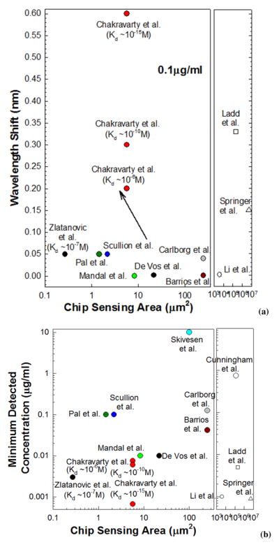
Charts comparing sensitivities of PC microcavity based biosensors demonstrated here versus other label-free optical platforms as a function of sensing area on chip. (a) Sensitivity comparison at mass concentration 100ng/ml. (b) Comparison of minimum detection limits. Results from this research are shown as filled circles in red.
5. Conclusions
In summary, we demonstrated here that high Q high sensitivity photonic crystal microcavity biosensors in silicon-on-insulator substrates can be realized by engineering the radiation loss and the optical mode volume in addition to optical propagation loss control by group index taper engineering. We also demonstrated that the sensitivity of photonic crystal microcavity sensors is a function of the dissociation constant. We demonstrated the highest sensitivity among optical biosensors in silicon at the probe biomolecule concentration of 0.1μg/ml, to our best knowledge, irrespective of the dissociation constant Kd of the binding kinetics. Multiple photonic crystal microcavity sensors can be connected with integrated waveguides, leading to a platform for high throughput, highly sensitive diagnostic assays that will broadly benefit the microarray end-user community.
Acknowledgments
The authors acknowledge the National Cancer Institute for supporting this work under the Small Business Innovation Research (SBIR) program (Contract # HHSN261201000085C).
Footnotes
Publisher's Disclaimer: This is a PDF file of an unedited manuscript that has been accepted for publication. As a service to our customers we are providing this early version of the manuscript. The manuscript will undergo copyediting, typesetting, and review of the resulting proof before it is published in its final citable form. Please note that during the production process errors may be discovered which could affect the content, and all legal disclaimers that apply to the journal pertain.
References
- Akahane Y, Asano T, Song BS, Noda S. Nature. 2003;425:944–947. doi: 10.1038/nature02063. [DOI] [PubMed] [Google Scholar]
- Barrios CA. Sensors. 2009;9:4751–4765. doi: 10.3390/s90604751. [DOI] [PMC free article] [PubMed] [Google Scholar]
- Carlborg CF, Gylfason KB, Kazmierczak A, Dortu F, Banuls Polo MJ, Maquieira Catala A, Kresbach GM, Sohlstrom H, Moh T, Vivien L, Popplewell J, Ronan G, Barrios CA, Stemme G, vander Woongaart W. Lab on a Chip. 2010;10:281–290. doi: 10.1039/b914183a. [DOI] [PubMed] [Google Scholar]
- Chakravarty S, Topol’ančik J, Bhattacharya P, Chakrabarti S, Kang Y, Meyerhoff ME. Opt Lett. 2005;30:2578–2580. doi: 10.1364/ol.30.002578. [DOI] [PubMed] [Google Scholar]
- Densmore A, Vachon M, Xu DX, Janz S, Ma R, Li YH, Lopinski G, Delage A, Lapointe J, Luebbert CC, Liu QY, Cheben P, Schmid JH. Opt Lett. 2009;34:3598–3600. doi: 10.1364/OL.34.003598. [DOI] [PubMed] [Google Scholar]
- de Feijter JA, Benjamins J, Veer FA. Biopolymers. 1978;17(7):1759–1772. [Google Scholar]
- de Groote D, Marchant A, Fauchet F, Jadoul M, Dehart I, Gerard C, Gevaert Y, Lopez M, Gathy R, Franssen JD, Radoux D, Franchimont P. J Immunological Methods. 1994;177:225–234. doi: 10.1016/0022-1759(94)90160-0. [DOI] [PubMed] [Google Scholar]
- De Vos K, Bartolozzi I, Schacht E, Bientsman P, Baets R. Opt Exp. 2007;15(12):7610–7615. doi: 10.1364/oe.15.007610. [DOI] [PubMed] [Google Scholar]
- Dorfner D, Zabel T, Hurlimann T, Hauke N, Frandsen L, Rant U, Abstreiter G, Finley J. Biosens and Bioelectron. 2009;24:3688–3692. doi: 10.1016/j.bios.2009.05.014. [DOI] [PubMed] [Google Scholar]
- Iqbal M, Gleeson MA, Spaugh B, Tybor F, Gunn WG, Hochberg M, Baehr-Jones T, Bailey RC, Gunn LC. IEEE J Sel Top Quant Electron. 2010;16:654–661. [Google Scholar]
- Kang C, Phare CT, Vlasov YA, Assefa S, Weiss SM. Opt Express. 2010;18:27930–27937. doi: 10.1364/OE.18.027930. [DOI] [PubMed] [Google Scholar]
- Kuo SC, Lauffenburger DA. Biophysical Journal. 1993;65:2191–2200. doi: 10.1016/S0006-3495(93)81277-3. [DOI] [PMC free article] [PubMed] [Google Scholar]
- Lai WC, Chakravarty S, Zou Y, Chen RT. Optics Lett. 2012 (Accepted) [Google Scholar]
- Lee M, Fauchet PM. Opt Express. 2007;15:4530–4535. doi: 10.1364/oe.15.004530. [DOI] [PubMed] [Google Scholar]
- Li H, Fan X. Appl Phys Lett. 2010;97:011105-1–011105-3. [Google Scholar]
- Lin CY, Wang X, Chakravarty S, Lee BS, Lai WC, Chen RT. Appl Phys Lett. 2010;97:183302-1–183302-3. [Google Scholar]
- Mandal S, Erickson D. Opt Exp. 2008;16(3):1623–1631. doi: 10.1364/oe.16.001623. [DOI] [PMC free article] [PubMed] [Google Scholar]
- Nelson DL, Cox MM. Lehninger Principles of Biochemistry. 5. W.H. Freeman Macmillan; New York: 2008. [Google Scholar]
- Pal S, Guillermain E, Sriram R, Miller BL, Fauchet PM. Biosens and Bioelectron. 2011;26:4024–4031. doi: 10.1016/j.bios.2011.03.024. [DOI] [PMC free article] [PubMed] [Google Scholar]
- Scullion MG, Di Falco A, Krauss TF. Biosens and Bioelectron. 2011;27:101–105. doi: 10.1016/j.bios.2011.06.023. [DOI] [PubMed] [Google Scholar]
- Sipova H, Zhang S, Dudley AM, Galas D, Wang K, Homola J. Anal Chem. 2010;82:10110–10115. doi: 10.1021/ac102131s. [DOI] [PMC free article] [PubMed] [Google Scholar]
- Subramanian A, Kennel SJ, Oden PI, Jacobson KB, Woodward J, Doktycz MJ. Enzyme and Microbial Technology. 1999;24:26–34. [Google Scholar]
- Tan CP, Cipriany BR, Lin DM, Craighead HG. Nano Lett. 2010;10:719–725. doi: 10.1021/nl903968s. [DOI] [PMC free article] [PubMed] [Google Scholar]
- Zlatanovic S, Mirkarimi LW, Sigalas MM, Bynum MA, Chow E, Robotti KM, Burr GW, Esener S, Grot A. Sens and Actuators B. 2009;141:13–19. [Google Scholar]


