Abstract
When an azobenzene-containing polymer film is exposed to non-uniform illumination, a light-induced mass migration process may be induced, leading to the formation of relief patterns on the polymer-free surface. Despite many years of research effort, several aspects of this phenomenon remain poorly understood. Here we report the appearance of spiral-shaped relief patterns on the polymer film under the illumination of focused Laguerre–Gauss beams with helical wavefronts and an optical vortex at their axis. The induced spiral reliefs are sensitive to the vortex topological charge and to the wavefront handedness. These findings are unexpected because the doughnut-shaped intensity profile of Laguerre–Gauss beams contains no information about the wavefront handedness. We propose a model that explains the main features of this phenomenon through the surface-mediated interference of the longitudinal and transverse components of the optical field. These results may find applications in optical nanolithography and optical-field nanoimaging.
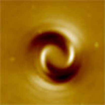 Non-uniform light beams can create patterns in azo-polymer films by inducing mass transport, yet the process is not well understood. Using optical vortex beams, Ambrosio et al. observe the formation of spiral patterns that are surprisingly sensitive to the optical phase, which they explain with a new model.
The illumination of a film of a polymer containing azobenzene moieties by means of linearly polarized light, in the UV/visible wavelengths region, leads to the reorientation of the azobenzene units perpendicularly to the light polarization direction1,2. This effect is believed to result from the light-induced trans–cis–trans isomerization cycles of the azo-unit, associated with random molecular reorientations, which continue until the rod-like trans-isomer becomes perpendicular to the electric field vector and thus stops absorbing light (although alternative ideas have also been put forward, see, for example, refs 3, 4). In 1995, however, another subtler phenomenon was observed in these materials5,6, namely a light-induced molecular displacement (or 'mass migration') occurring on the polymer-free surface and leading to the formation of stable-patterned surface reliefs7,8,9,10. A fingerprint of this phenomenon is the conservation of volume: protrusions and hollows appearing on the sample surface preserve the polymer volume on the mesoscopic length scale. These topographical features can be erased by heating the polymer above the glass transition temperature or by illuminating with incoherent uniform light11. These writing/erasing phenomena make azo-polymers very attractive for optical data storage applications. The light-induced surface reliefs could also be used for imaging the electromagnetic field distributions resulting from local illumination by means of near-field sources12,13,14,15,16 and optical nano-antennas17. Recently, the potential advantage of using azo-polymers in the place of sacrificial photoresists in the fabrication of silicon micro- and nano-structures arrays has also been demonstrated18,19. A very recent comprehensive review on the science and applications of photoinduced micro and nanostructuring of azobenzene materials is in ref. 20.
The origin of the mass transport-driving force is still debated20,21,22,23,24,25,26,27,28,29,30. All currently proposed models however share a common element: the light-induced mass-transport action is linked to the optical field via its intensity gradients. The relationship is vectorial, as the mass transport appears to occur preferentially in the direction of the electric field6,7,22,31. However, apparently nothing in these models predicts a sensitivity of the light-induced mass transport to the wavefront structure of the writing beam. Hence, different optical fields sharing the same polarization and intensity profile would be expected to give rise to the same surface relief patterns. This naïve prediction can be tested, for example, by comparing the patterns induced by two optical vortex beams having opposite wavefront handedness, as we will discuss below.
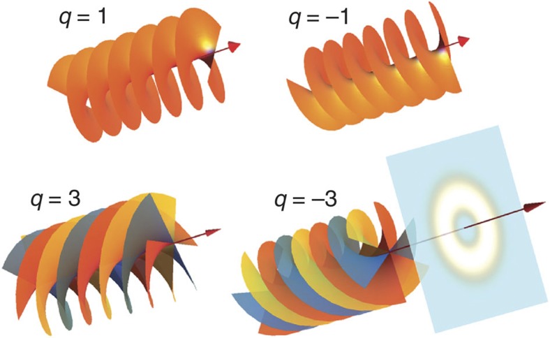
The concept of an 'optical vortex'—or 'wave-train screw-type dislocation', as it was initially called—was first introduced by Nye and Berry32 in 1974. The Laguerre–Gauss (LG) beams are the best-known examples of optical modes endowed with an optical vortex located at their beam axis33. The optical phase of these modes varies by 2πq when circling once the beam axis, where q is an integer, positive or negative, called the vortex topological charge. At the axis, that is, the core of the vortex, the phase is undefined and the optical field must vanish (for non-zero q), thus giving rise to the characteristic doughnut shape of the beam intensity cross-section (see Fig. 1). LG beams are characterized by a helical-shaped wavefront, as shown in Fig. 1, and carry so-called orbital angular momentum (OAM)34,35. Vortex beams very similar to LG modes, hereafter named LG-like beams, can be conveniently generated from ordinary Gaussian laser beams by diffraction on a suitable pitchfork hologram displayed on a spatial light modulator (SLM)36,37,38.
Figure 1. Vortex beams.
Schematics of the vortex-beam optical field employed in the present work. Shown are the wavefront helical structures for vortex topological charges q=±1 and q=±3 (in the latter case, the wavefront is composed of three intertwined helical surfaces, here shown in different colours for clarity) and, in the last example, the associated doughnut-shaped transverse intensity distribution.
Here, we exposed a thin azo-polymer film to focused LG-like vortex beams of varying vortex charge and handedness. The induced spiral reliefs are found to be sensitive to the vortex topological charge and in particular to the wavefront handedness, thus showing that the polymer is responding not only to the intensity distribution of the light field in the focus but also to its phase. We explain the main qualitative features of this phenomenon with a symmetry-based phenomenological model and discuss the possible underlying microscopic mechanisms at work.
Results
Experiment
The material used in our experiment is an acrylic polymer bearing the photo-responsive moieties as side chains of the polymeric backbone (see inset Fig. 2a for the polymer structure). The polymer is spin coated onto 170-μm thick microscope coverslips. The material absorption spectrum shows a broad maximum in the UV/visible wavelengths region (Fig. 2a) in accordance with those usually reported for polymers containing azobenzene moieties. At the working wavelength of 532 nm, the polymer film total absorbance is about 5%.
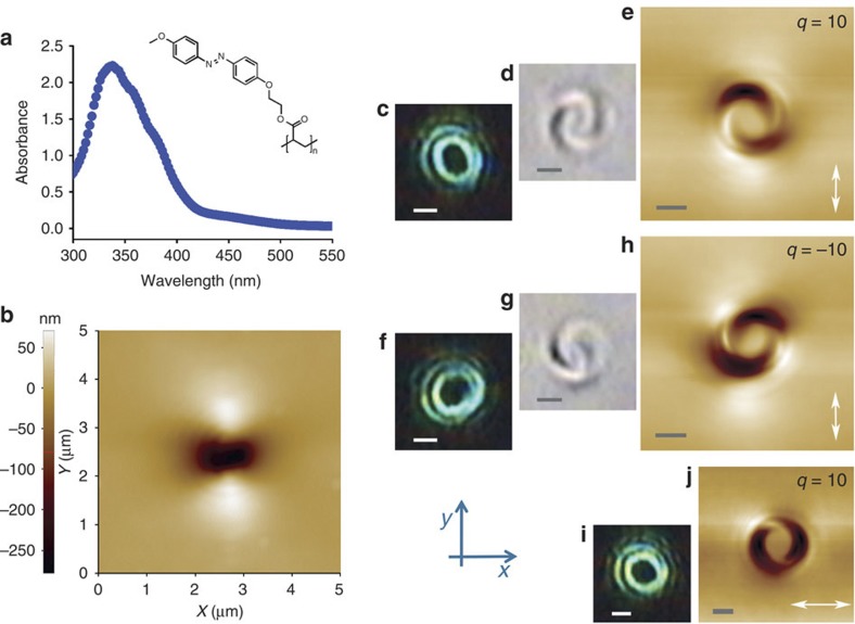
Figure 2. Light-induced surface relief patterns on the azo-polymer film.
(a) Absorption spectrum of the azo-polymer used in this work. Inset: polymer structure. (b) Surface relief pattern induced by a focused Gaussian beam (topological charge q=0). The material displacement leads to a two-lobed pattern oriented along the beam polarization direction (y-axis), as already reported in previous works7,8. (c) Optical micrograph of the intensity pattern of a LG-like vortex beam having topological charge q=10, focused by a 1.3 NA oil-immersion microscope objective on the surface of a coverslip where a metallic mirror is inserted in the place of the sample. (d) Optical micrograph of the polymer surface relief pattern generated by the focused q=10 vortex beam (linearly polarized along the y-direction). The image is taken by means of the same objective used to illuminate the sample. (e) AFM image of the same surface relief pattern as in panel d. (f) Optical micrograph of the intensity pattern when the vortex handedness is inverted (topological charge q=−10; still linearly polarized along the y-direction). (g) Optical micrograph of the polymer surface relief pattern induced after inverting the vortex handedness. (h) AFM image of the same structure as in panel g. (i) Optical micrograph of the intensity pattern obtained for a vortex beam with q=10, when the light polarization direction is rotated by 90° (so as to be parallel to the x-axis). (j) AFM surface relief pattern corresponding to the illumination conditions of panel i: the two arms of the spiral are rotated by 90°, as compared with the pattern shown in panel e. The white arrow in panels e, h and j indicates the polarization direction of the light. The scale bars in panels c–j correspond to 1 μm.
The optical apparatus used for writing the polymer relief structures is shown in Fig. 3. The laser beam, initially in a TEM00 Gaussian mode, is injected into an inverted optical microscope and focused on the sample surface by means of an oil-immersion 1.3-numerical aperture (NA) microscope objective. The laser polarization direction before the focalization is linear. The atomic force microscope (AFM) scanning, reported in Fig. 2b, shows the topographical features obtained on the film surface (polymer–air interface) in this illumination condition. In good agreement with results previously reported in the literature7,8, we find the formation of two protrusions along the laser polarization direction, with a central hollow. The film thickness is approximately 700 nm, the exposure time is 90 s and the laser power injected into the microscope is 13 μW, corresponding to about 5 μW of estimated exposure power on the polymer. Next, LG-like vortex beams were generated by diffraction on a phase-only SLM and injected in the microscope. Figure 2c shows a photomicrograph of the resulting doughnut intensity profile of the focused beam on the sample (see Methods). This specific beam carries an optical vortex of charge q=10, chosen here because the resulting relief pattern is particularly large and clear. By calibrating the pixel dimension in the micrograph, the inner and outer diameters of the laser spot (including also the outer rings) are measured to be, respectively, 1.2±0.2 and 3.2±0.3 μm at 10% of the maximum intensity. An optical micrograph of the polymer relief pattern induced by this illumination condition is reported in Fig. 2d: a two-arm spiral structure is evident. However, this optical image is affected by light diffraction and the image contrast may result from both the topography modulation and the azo-molecule orientation (local refractive index) in the illuminated region. The actual relief spiral pattern can be observed in the AFM topographical map of the sample surface (Fig. 2e). We stress that no evidence of a spiral structure is present in the light-intensity pattern shown in Fig. 2c. Therefore, we are led to conclude that the light-induced mass transport is somehow responding not only to the intensity pattern but also to the helical structure of the wavefront around the vortex. This conclusion is confirmed when the sign of the optical vortex topological charge is inverted, a change leaving the intensity pattern approximately unmodified (Fig. 2f; we ascribe the small variation in the laser-spot shape to a small residual astigmatism in the optical set-up, as high-charge vortex beams are extremely sensitive to astigmatism): the resulting polymer relief pattern is found to have the opposite handedness, as shown in Fig. 2g (optical micrograph) and Fig. 2h (AFM micrograph). Figures 2i and j show instead the polarization dependence of the intensity distribution and of the resulting relief pattern, respectively: a 90° rotation of the polarization vector leads to almost no variation of the light-intensity distribution, but to a similar 90° rotation of the resulting polymer spiral pattern.
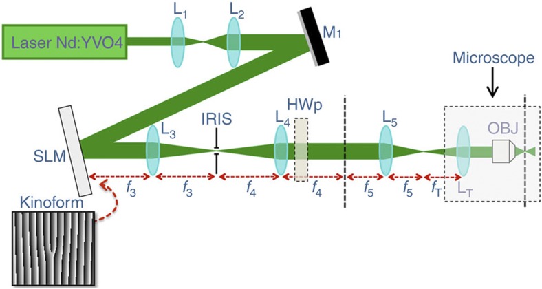
Figure 3. Optical apparatus.
The laser beam (from a Nd:YVO4 continuous-wave frequency-duplicated laser), after a beam expander (lenses L1 and L2), is reflected by mirror M1 onto a computer-controlled SLM, which is programmed for visualizing a pitchfork hologram (kinoform) generating the desired LG-like beam with a prescribed topological charge. Next, the first-order diffracted beam is selected via an iris located in the focal plane of a lens (L3). After recollimation (lens L4), the beam is sent through a half-wave plate (HWp) for rotating the input polarization and finally imaged by external lens L5 and the internal lens system of the microscope (including tube lens LT and the microscope objective OBJ) to the sample plane, positioned at the polymer surface. The dashed lines mark the image planes reproducing the optical field after SLM diffraction. Segments fi denote the focal lengths of the corresponding lenses Li.
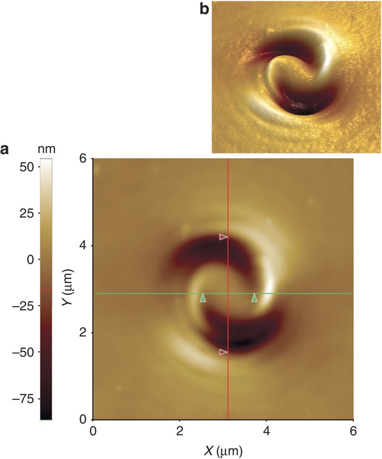
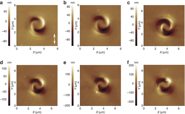
Further details about the observed spiral relief patterns are provided in Fig. 4 with the AFM topographical map of a structure obtained under illumination by a q=10 beam. In particular, the cursors in the image mark the inner (green cursors) and outer (red cursors) diameters of the affected polymer region, which are approximately coincident with the inner and outer diameters of the laser spot shown in Fig. 2c. Hence, it is evident that the material displacement mainly occurs in the illuminated region, whereas the inner part of the structure is made of unperturbed polymer (having the same height as the unexposed polymer at the picture's edge). Finally, Fig. 5 shows the dependence of the observed patterns on the light intensity. The most striking observation here is that while the height/depth of the patterns increases with a higher light intensity, the shape of the patterns remains approximately unchanged. Similar results are obtained for a varying exposure time at fixed light intensity.
Figure 4. Two- and three-dimensional AFM maps of a light-induced polymer spiral structure.
(a) Two-dimensional AFM image of the topographical structure obtained at the sample surface when the polymer is illuminated by a focused q=10 vortex beam. The distances between the two green and the two red cursors, taken along the corresponding lines passing through the structure centre, are 1.2 and 2.7 μm, respectively. These values are consistent with the inner and outer diameters of the laser spot shown in Fig. 2c. (b) Three-dimensional rendering of the same AFM map.
Figure 5. Spiral relief patterns obtained for different illumination doses.
AFM images of the topographical structures obtained for varying illumination intensity and fixed time of exposure (and polarization direction), for topological charge q=10. The white arrow indicates the polarization direction. Different panels correspond to different values of the laser power injected in the microscope: (a) 15 μW; (b) 18 μW; (c) 21 μW; (d) 29 μW; (e) 41 μW; (f) 54 μW. Similar results are obtained for varying time of exposure at fixed intensity.
Theory
No model ascribing the mass transport only to the light intensity gradients is capable of describing our results. The spiral arms appearing in the relief pattern must somehow reflect the helical structure of the wavefront, which is lost in the field amplitudes, even separating the three Cartesian field components. One could be tempted to ascribe the spiral relief pattern to a rotational flow induced in the polymer by the absorbed light OAM, but this hypothesis appears to be in contrast with the observation that the pattern keeps the same shape independent of the illumination time or intensity (see Fig. 5), while one would expect instead that the OAM-induced rotational flow makes the spirals wind more for a longer or more intense exposure. Moreover, an order-of-magnitude estimate of the expected induced rotation for our light illumination conditions shows that this effect should be negligible, even assuming a complete light-induced fluidization of the polymer, unless the viscosity dropped to unrealistically small values.
On the other hand, we have found that a double-arm spiral pattern reflecting the wavefront handedness may appear if an interference between the transverse optical field components Ex and Ey and the longitudinal component Ez is involved in the process. Such an interference term is normally absent in isotropic media, but it may become allowed (for a tensorial response of the material) when the rotational symmetry is broken, and in particular in the presence of the medium surface discontinuity, as in our case. Starting from this insight, we have developed a symmetry-based phenomenological theory of the light-induced mass transport process not relying on any specific microscopic model. Our theory is probably oversimplified, as it neglects the viscoelastic couplings in the polymer and the surface tension effects, but nevertheless it is expected to capture the main features of the light-driving forces and therefore the qualitative properties of the resulting relief patterns. In the following, we present only the main lines of our theory, while more details are given in the Supplementary Methods.
The starting assumption of our model is that the optical field induces a mass current J that is determined only by the electric field amplitudes and its gradients via a local constitutive relation, to be determined using symmetry constraints. In a two-dimensional (2D) approximation, valid in the limit of a very thin polymer film lying in the xy plane, the most general 2D vector that can be built out of quadratic terms in the optical electric field (which are the lowest-order non-vanishing ones, after time averaging over the field optical oscillations) and their gradients (which describe the lowest-order non-local dependences in a Taylor expansion) is:
 |
where E=(Ex, Ey, Ez) is the optical electric field in the polymer film (in complex notation), C1, C2, C3 and CB are constants characterizing the polymer, L is an effective film thickness, ∂k stands for the partial derivative ∂/∂xk, and sum over repeated indices is understood. This vector may be taken to represent the polymer 2D mass current in the xy plane (averaged over the thickness L along z). A more detailed fully three-dimensional (3D) analysis is provided in the Supplementary Methods, where it is also established that C1, C2 and C3 are real-valued quantities linked to bulk processes, while CB has a dominating surface contribution (so that the resulting z-averaged current scales as 1/L) and in general it might also be complex-valued. Nevertheless, if the field quadratic terms are taken to originate from electric-dipole absorption effects, then also CB must be real, and we will make this assumption in the following. In the Discussion, we will analyse the physical meaning of these four mass-current terms.
By exposing the polymer to a constant illumination pattern for a certain time τ, the light-induced mass current will give rise to a pattern Δh(x,y) of surface 'height' variations across the polymer film. Neglecting all possible relaxation effects counteracting the mass migration (for example, viscoelastic effects, surface tension and so on) and assuming approximate incompressibility of the polymer, Δh(x,y) will be given by the following expression (see Supplementary Methods for details):
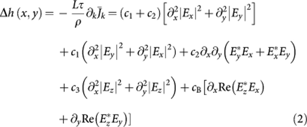 |
where ρ is the mass density and we set c1=(Lτ/ρ)C1, c2=(2Lτ/ρ)C2, c3=(Lτ/ρ)C3, and cB=(τ/ρ)CB.
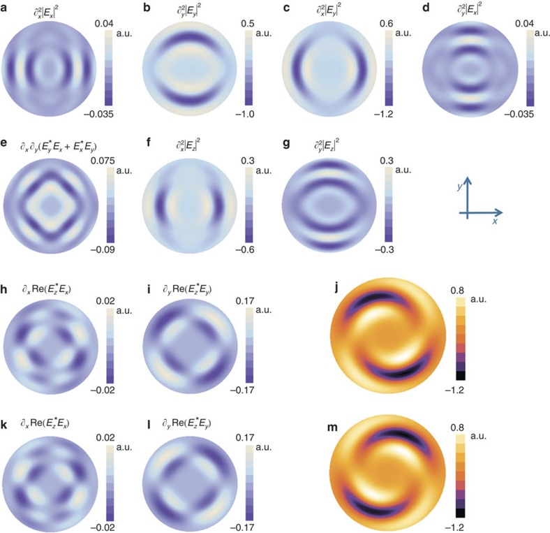
Relief pattern simulations
Figure 6a–i reports the simulated distributions, at the focal plane of the objective, of each term appearing in Equation (2), for a q=5 vortex beam, linearly polarized along the y-axis (see Methods for details about the simulations). We choose the q=5 example instead of q=10 here because its smaller overall extension allows the use of a smaller spatial scale in the images of the predicted relief patterns, thus showing greater detail. Figure 6j shows the total Δh(x,y) distribution predicted for the exposed polymer surface as obtained by combining all terms (from Fig. 6a–i), as stated by equation (2). In this figure and in the following ones, we set c1=0, c2=1, c3=0, cB=8 (c2/λ). Indeed, in our system c1 and c3 are found to be negligible with respect to c2 when comparing the theoretical pattern predicted by equation (2) with the observations in the case of a linearly polarized Gaussian laser beam with q=0 (see Supplementary Methods). Therefore, only the ratio cB/c2 was adjusted to best reproduce the qualitative experimental features of the spiral-shaped structures induced by vortex beams. The resulting pattern Δh(x,y) (Fig. 6j) is in very good qualitative agreement with the experimental topographical distribution reported in Fig. 4. In particular, as discussed above, the terms that give rise to the spiral structure are those proportional to the constant cB, corresponding to the interference between the transverse components Ex and Ey and the longitudinal one Ez, shown in Fig. 6h and i. Furthermore, Fig. 6k–m show the distributions obtained when q=−5. In fact, whereas terms in Fig. 6a–g are identical for both q=5 and q=−5, terms of Fig. 6h and i are modified into those reported in Fig. 6k and l, respectively. The total relief pattern predicted for q=−5 is given in Fig. 6m, which shows the same handedness inversion effect of the spiral arms that we have observed in the experiment (Fig. 2h). Moreover, as in the simulation the only consequence of rotating the polarization direction by 90° is to swap x and y components (plus a sign change), it is clear that our model accounts also for the polarization dependence observed in Fig. 2j.
Figure 6. Surface relief patterns corresponding to the various terms appearing in our model.
(a) Contribution to the surface relief pattern resulting from the second-derivative term ∂x2|Ex|2 appearing in our model, based on the simulations of the optical field at the focus, for a tightly focused q=5 vortex beam, linearly polarized along the y-axis. The relief scale is in arbitrary units. The simulated area is a circle of four times the light wavelength in diameter. (b–i), Same as in panel a, for the other field-derivative terms appearing in our model and displayed above each panel. (j) Total surface relief pattern obtained by combining all terms as in Equation (2), with the constants' values set to: c1=0; c2=1; c3=0; cB=8 (c2/λ). (k–m) Same as for panels h–j, respectively, when the vortex beam charge is inverted to q=−5 (all other terms remain unchanged).
It is worth noting that the terms displayed in Fig. 6h and i or k and l, corresponding to the interference between transverse and longitudinal field components, vanish identically (or are negligible) in the case of light beams that do not have a vortex structure or a helical wavefront. To our knowledge, these include all the illumination patterns used in the previously reported experiments. This is the reason why the wavefront-sensitive mass transport effects reported here have not been noticed before.
Comparison between theory and experiment
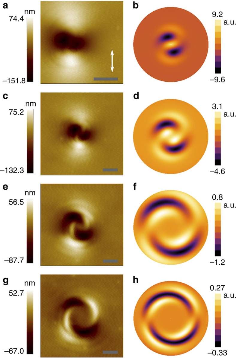
We have already shown that our model can qualitatively explain the two-arms spiral shape of the polymer relief pattern, its dependence on the optical wavefront handedness and its polarization dependence. In addition, Fig. 7 reports the evolution of the twisting of the experimental and theoretical polymer structures as a function of the vortex-beam topological charge q. The qualitative agreement between experiment and theory is evident. In detail, by increasing q from 1 to 10, the experimental and theoretical patterns both show an increasing transverse extension, a decreasing height and depth of the reliefs and an increasing rotation angle of the spiral arms with respect to the y-axis. However, the model does not fully account for the somewhat different behaviour of the topographic maxima and minima, which are asymmetric in the experiments and more symmetric in the simulations. This and other more quantitative discrepancies are presumably due to the occurrence of viscoelastic and surface tension stresses in the polymer during the experiment, opposing the material displacement, which are not accounted for in our simplified theory. A more quantitative model will be developed in future work, by combining the photoinduced current given in equation (1) with viscous forces so as to write a generalized Navier–Stokes equation25, to be complemented with the appropriate boundary conditions for the polymer flow and surface tension effects.
Figure 7. Evolution of the light-induced surface relief patterns as a function of the vortex-beam topological charge.
The topological charge increases when moving from the top to the bottom of the figure. (a) Topographical AFM map of the pattern obtained with a q=1 vortex beam, linearly polarized as indicated by the white arrow. (b) Corresponding simulation based on our model. (c) and (d), same as for panels a and b, respectively, but in the case q=2. (e) and (f), in the case q=5. (g) and (h), in the case q=10. The scale bars of all the AFM maps correspond to 900 nm. The simulated area in panels b, d and f has a diameter of 4 times the wavelength, whereas in panel h, it has a diameter of 7.3 times the wavelength.
Discussion
We have introduced a symmetry-based phenomenological theory for the light-induced mass transport that needs no assumptions about the underlying microscopic mechanism. From a practical point of view, this is an advantage of our approach, as there is no consensus yet about the correct microscopic picture20. Our phenomenological theory is powerful enough to make specific predictions about the induced patterns, particularly after determining the value of its four phenomenological coefficients C1, C2, C3 and CB, which in our lowest-order approximation may only depend on the material properties. The predicted 2D current given in equation (1) presents four corresponding separate terms, whose phenomenological physical meaning can be given in terms of the resulting mass-transport effects. For example, the current term in C1 corresponds to a mass migration along the gradient of the total transverse intensity ( ), hence it is just driving the polymer molecules out of the bright regions (assuming C1>0), irrespective of the polarization direction. In our theory, this term is the only possible cause of the relief gratings obtained for s-s polarized two-beam interference (see Supplementary Methods), which are usually found to be much less pronounced than the gratings obtained for other polarization combinations20 (this shows that C1 is small in most materials). The term in C3 gives rise to the same intensity-gradient effect, but accounting for the additional intensity associated with the longitudinal field
  (and for an isotropic 3D polymer response, we must have C1=C3, as shown in the Supplementary Methods; so also C3 is likely small). The term in C2 is instead causing the polarization-sensitive anisotropic mass transport, by inducing motion only along the direction of the electric field. This term is for example what makes the relief gratings induced by p-p polarized two-wave interference much more pronounced than s-s ones (see, for example, ref. 20). It also causes the directional fluidization reported in ref. 31, and gives rise to the two lobes appearing after illumination by a single linearly polarized Gaussian beam (see, for example, Fig. 2a and ref. 7). Thus, former investigations concur in indicating that the term in C2 is the dominating one, consistent with the assumptions C1=C3=0 used in our simulations. Finally, the newly predicted current term in CB is what induces the spiral transport effect, being sensitive to the wavefront handedness via the interference of the longitudinal and transverse field components.
Let us now briefly discuss the possible physical meaning of these four current terms in connection with one of the microscopic mechanisms that have been proposed in the literature to explain the mass migration. Such microscopic models are reviewed in ref. 20 (see, for example, Table 1), with the conclusion that no single model is presently capable of explaining all observed features of the photoinduced phenomena in azobenzene materials. Probably, a realistic model must combine several effects, as for example, attempted in the numerical simulations reported in ref. 30. Nevertheless, we have developed an analytical microscopic model based on the light-induced anisotropic diffusion (or random walk) of the molecules as the main underlying mechanism to explain the mass migration24,28,29, which is also one of the key ingredients of the simulations reported in ref. 30. We will publish the details of this model elsewhere, but we can anticipate here that its results are entirely consistent with those of our phenomenological theory. In the framework of this specific microscopic model, the mass-current terms with coefficients C1, C2 and C3 appearing in our equation (1) are associated with the light-driven anisotropic molecular diffusion of azobenzene moieties occurring in the polymer bulk, with the diffusion along the polarization direction being strongly favored by the more likely excitation of the azo-molecule chromophores aligned along the electric field direction. The CB term is associated with a similar light-driven anisotropic diffusion, but combined with an enhanced mobility of the azo molecules lying close to the polymer boundaries (in particular at the polymer surface) and with the obvious additional constraint that the molecules cannot leave the polymer medium. We stress, however, that this specific microscopic interpretation of the light-induced mass currents must be regarded as tentative, at this stage.
In conclusion, we have shown that a solid film made of an azobenzene-containing polymer is sensitive to the helical wavefront handedness of a doughnut laser beam, so as to develop spiral-shaped relief patterns responding to the wavefront handedness and topological charge. We ascribe this phenomenon to the action of an unusual, perhaps unprecedented, interference between longitudinal and transverse optical field components, made possible by the symmetry breaking taking place at the polymer surface. Our findings open new possibilities in azo-polymer-based micro- and nano-lithography18,19, allowing the design of more complex patterns by exploiting the light wavefront as an additional control handle. Furthermore, the insights provided by our model, by advancing our understanding of the link between the driving optical field and the resulting polymer topographical patterns, will contribute to exploiting the light-induced mass-migration phenomenon for the non-optical nano-imaging of near-field electromagnetic sources and scattering elements20.
Methods
Synthesis of the azobenzene-containing polymer
The reagents for the synthesis were purchased from Aldrich and used without further purification. 1H nuclear magnetic resonance (NMR) spectra were recorded on a Varian XL 200 MHz and chemical shifts are reported as δ values (p.p.m.) relative to internal Me4Si. Differential scanning calorimetry measurements were performed on an indium-calibrated Perkin–Elmer Pyris 1 apparatus, under a dry nitrogen atmosphere with a temperature scanning rate of 10 °C per minute. UV/visible absorption spectra were recorded with a Jasco V560 spectrophotometer in chloroform.
The photoresponsive monomer is an azobenzene with symmetric distribution of alkoxy substituents and a terminal acrylic group, (E)-2-(4-((4-methoxyphenyl) diazenyl)phenoxy)ethyl acrylate. The monomer was synthesized according to a method reported in the literature39,40. The polymer was obtained by radical polymerization of the monomer in solution according to the following procedure. (E)-2-(4-((4-methoxyphenyl)diazenyl)phenoxy)ethyl acrylate (1.00 g, 3.06 mmol) and 2,2′-azobis(2-methylpropionitrile) (0.0100, g, 6.09·10−2 mmol) were dissolved in 4 ml of N,N-dimethylformamide in a vial that was sealed under vacuum after three 'freeze and thaw' cycles. The solution was kept at 70 °C for 48 h and then poured into 100 ml of methanol. The polymer was filtered, washed with methanol, dissolved in chloroform and precipitated in hexane. 1H NMR (CDCl3, 200 MHz): δ 1.20 (s); 1.68 (s); 1.97 (s); 2.48 (s); 3.82 (s); 4.02 (s); 4.29 (s); 6.89 (s); 7.78 (s). Phase sequence: G 67 °C N 113 °C I (G: glass, N: nematic, I: isotropic). UV-visible: λmax 356 nm.
The 1H NMR spectrum of the polymer shows broad singlets, no acrylate resonances and four signals in the aliphatic region, owing to a significant amount of insertion errors and regio-irregularity generated in the experimental conditions. Thin films were deposited from 1,1,2,2-tetrachloroethane solution by filtering on 0.2 μm teflon filters and spin coating onto glass substrates. By means of this technique the polymer can be obtained in the amorphous state, which is stable at room temperature and the nematic phase only arises upon annealing. This behaviour allowed the realization of photoisomerization experiments on unstructured samples. The endothermal transition at 113 °C corresponds to isotropization of the nematic phase. Differential scanning calorimetry scans were also performed after isothermal treatments at 90 °C for 0.5, 1 and 2 h. The curves show the same peak area at 113 °C and hence unchanged heat of isotropization, thus indicating the nematic phase to form rapidly and completely after annealing the amorphous phase or cooling down from the isotropic region.
Optical apparatus and laser-spot imaging
The holographically produced vortex beams are obtained by means of a phase-only SLM (Pluto, by HOLOEYE Photonics AG). The input Gaussian beam is first spatially expanded to fill the SLM-active area (1,080 × 1,920 pixels, 8 μm wide each). The beam diffracted (in reflection) by the SLM is then propagated towards the microscope by means of two consecutive lens systems in telescopic configuration (see Fig. 3). The focal lengths of the lenses are chosen so as to achieve the correct magnification of the beam size before injecting it into the microscope objective. This is an inverted microscope where the image is formed by means of the same microscope objective used to focus the laser beam at the sample–air interface. The polymer film is spin coated on glass coverslips and matching oil is added in between the microscope objective and the coverslip-free surface. The laser-spot photomicrographs shown in Fig. 2 are obtained by mounting a digital camera in the place of the eyepieces. To avoid the typical aberrations in imaging by reflection from a dielectric interface when using high-NA objectives (see, for example, ref. 41), these photos were taken with a metallic mirror inserted on the top of the coverslip in the place of the polymer film sample (in this case, matching oil is also added in between the coverslip and the mirror surface). The multiple concentric rings observed for the intensity profile of a vortex beam (Fig. 2) are to be ascribed mainly to diffraction arising in the microscope objective, as we are in an overfilling geometry.
AFM measurements and image analysis
The AFM images were obtained using an atomic force microscope (XE-100 by Park Systems Corp.) working in non-contact mode. The image analysis has been performed using standard software provided by the same company.
Optical field simulations
The focalization of a linearly polarized beam by means of a high-NA microscope objective results in non-negligible field components along the other two Cartesian directions42. The complex quantities Ex, Ey and Ez of the electromagnetic field at the focal plane of the objective are obtained by using the angular spectrum representation of the field refracted by the lens combined with the stationary phase method for the evaluation of non-evanescent field components. The resultant quantities are then calculated by using numerical integration on the collection solid angle, for each of the points in the simulated area, in accordance to the work of Richards and Wolf43,44 for aplanatic lenses and the treatment reported, for instance, in ref. 41. An example of the results of these calculations is reported in Supplementary Fig. S1. The derivatives appearing in equation (2) are also numerically evaluated by approximating the spatial derivatives of the field components with the incremental ratios, with a spatial step of 0.01 times the light wavelength. This guarantees a good approximation of both the continuous fields and derivatives. An example of the results obtained in the case of a LG-like beam is shown in Fig. 6 and for an ordinary Gaussian beam in Supplementary Fig. S2.
Author contributions
A.A. conceived and conducted the experiments and performed the numerical simulations. L.M. developed the theoretical modelling. F.B. and A.R. synthesized the polymer and provided the samples. A.A., L.M. and P.M. discussed the experimental data and the simulation results and wrote the paper, with some input from the other authors. P.M. initiated and directed the project.
Additional information
How to cite this article: Ambrosio, A. et al. Information processing using a single dynamical node as complex system. Nat. Commun. 3:989 doi: 10.1038/ncomms1996 (2012).
Supplementary Material
Supplementary Figures S1-S2 and Supplementary Methods
Acknowledgments
The research leading to these results has received funding from the European Community, 7th Framework Programme, under Grant no. 264098—MAMA and under Grant no. 255914—PHORBITECH, the latter within the Future Emerging Technologies FET-Open programme.
References
- Barrett C., Natansohn A., Rochon P. Cis-trans thermal isomerization rates of bound and doped azobenzenes in a series of polymers. Chem. Mater. 7: 899–903 (1995) [Google Scholar]
- Seki T., Fukuda K., Ichimura K. Photocontrol of polymer chain organization using a photochromic monolayer. Langmuir 15: 5098–5101 (1999) [Google Scholar]
- Kreuzer M., Benkler E., Paparo D., Casillo G., Marrucci L. Molecular reorientation by photoinduced modulation of rotational mobility. Phys. Rev. E 68: 011701 (2003) [DOI] [PubMed] [Google Scholar]
- Manzo C., Paparo D., Marrucci L. Photoinduced random molecular reorientation by nonradiative energy relaxation: an experimental test. Phys. Rev. E 70: 051702 (2004) [DOI] [PubMed] [Google Scholar]
- Rochon P., Batalla E., Natansohn A. Optically induced surface gratings on azoaromatic polymer films. Appl. Phys. Lett. 66: 136–138 (1995) [Google Scholar]
- Kim D. Y., Tripathy S. K., Li L., Kumar J. Laser-induced holographic surface relief gratings on nonlinear optical polymer films. Appl. Phys. Lett. 66: 1166–1168 (1995) [Google Scholar]
- Bian S. et al. Single laser beam-induced surface deformation on azobenzene polymer films. Appl. Phys. Lett. 73: 1817–1819 (1998) [Google Scholar]
- Bian S. et al. Photoinduced surface deformations on azobenzene polymer films. J. Appl. Phys. 86: 4498–4508 (1999) [Google Scholar]
- Sobolewska A., Miniewicz A. On the inscription of period and half-period surface relief gratings in azobenzene-functionalized polymers. J. Phys. Chem. B 112: 4526–4535 (2008) [DOI] [PubMed] [Google Scholar]
- Gilbert Y. et al. Longitudinal anisotropy of the photoinduced molecular migration in azobenzene polymer films. Opt. Lett. 31: 613–615 (2006) [DOI] [PubMed] [Google Scholar]
- Jiang X. L., Li L., Kumar J., Kim D. Y., Tripathy S. K. Unusual polarization dependent optical erasure of surface relief gratings on azobenzene polymer films. Appl. Phys. Lett. 72: 2502–2504 (1998) [Google Scholar]
- Kawata Y. et al. Non-optically probing near-field microscopy. Opt. Commun. 161: 6–12 (1999) [Google Scholar]
- Bachelot R. et al. Apertureless near-field optical microscopy: a study of the local tip field enhancement using photosensitive azobenzene-containing films. J. Appl. Phys. 94: 2060–2072 (2003) [Google Scholar]
- Ishitobi H., Tunabe M., Sekkat Z., Kawata S. Nanomovement of azo polymers induced by metal tip enhanced near-field irradiation. Appl. Phys. Lett. 91: 091911 (2007) [Google Scholar]
- Hasegawa M., Ikawa T., Tsuchimori M., Watanabe O., Kawata Y. Topographical nanostructure patterning on the surface of a thin film of polyurethane containing azobenzene moiety using the optical near field around polystyrene spheres. Macromolecules 34: 7471–7476 (2001) [Google Scholar]
- Ambrosio A. et al. Noncontact tuning fork position sensing for hollow-pyramid near-field cantilevered probes. Appl. Phys. Lett. 89: 163108 (2006) [Google Scholar]
- Hubert C. et al. Near-field photocheminal imaging of noble metals nanostructures. Nano Lett. 5: 615–619 (2005) [DOI] [PubMed] [Google Scholar]
- Kravchenko A., Shevchenko A., Ovchinnikov V., Priimagi A., Kaivola M. Optical interference lithography using azobenzene-functionalized polymers for micro- and nanopatterning of silicon. Adv. Mater. 23: 4174–4177 (2011) [DOI] [PubMed] [Google Scholar]
- Won R. Azopolymer option. Nat. Photon 5: 649 (2011) [Google Scholar]
- Lee S., Kang H. S., Park J.-K. Directional photofluidization lithography: micro/ nanostructural evolution by photofluidic motions of azobenzene materials. Adv. Mater. 24: 2069–2103 (2012) [DOI] [PubMed] [Google Scholar]
- Barrett C. J., Rochon P. L., Natansohn A. L. Model of laser-driven mass transport in thin films of dye-functionalized polymers. J. Chem. Phys. 109: 1505–1516 (1998) [Google Scholar]
- Kumar J. et al. Gradient force: the mechanism for surface relief grating formation in azobenzene functionalized polymers. Appl. Phys. Lett. 72: 2096–2098 (1998) [Google Scholar]
- Pedersen T. G., Johansen P. M., Holme N. C. R., Ramanujam P.S., Hvilsted S. Mean-field theory of photoinduced formation of surface reliefs in side-chain azobenzene polymers. Phys. Rev. Lett. 5: 89–92 (1998) [Google Scholar]
- Lefin P., Fiorini C., Nunzi J.-M. Anisotropy of the photo-induced translation diffusion of azobenzene dyes in polymer matrices. Pure Appl. Opt. 7: 71–82 (1998) [Google Scholar]
- Sumaru K., Yamanaka T., Fukuda T., Matsuda H. Photoinduced surface relief gratings on azopolymer films: analysis by a fluid mechanics model. Appl. Phys. Lett. 75: 1878–1880 (1999) [Google Scholar]
- Bublitz D., Fleck B., Wenke L. A model for surface-relief formation in azobenzene polymers. Appl. Phys. B 72: 931–936 (2001) [Google Scholar]
- Sumaru K., Fukuda T., Kimura T., Matsuda H., Yamanaka T. Photoinduced surface relief formation on azopolymer films: a driving force and formed relief profile. J. Appl. Phys. 91: 3421–3430 (2002) [Google Scholar]
- Bellini B. et al. Light-induced molecular motion of azobenzene-containing molecules: a random-walk model. J. Phys. Condens. Matter 18: S1817–S1835 (2006) [Google Scholar]
- Juan M. L. et al. Stochastic model for molecular transport in polymer films. Appl. Phys. Lett. 93: 153304 (2008) [Google Scholar]
- Juan M. L. et al. Multiscale model for photoinduced molecular motion in azo polymers. ACS Nano 3: 1573–1579 (2009) [DOI] [PubMed] [Google Scholar]
- Karageorgiev P. et al. From anisotropic photo-fluidity towards nanomanipulation in the optical near-field. Nat. Mater. 4: 699–703 (2005) [DOI] [PubMed] [Google Scholar]
- Nye J. F., Berry M. V. Dislocations in wave train. Proc. R. Soc. Lond. A 336: 165–190 (1974) [Google Scholar]
- Yariv A. Quantum Electronics 3rd edn. (John Wiley & Sons (1989) [Google Scholar]
- Franke-Arnold S., Allen L., Padgett M. J. Advances in optical angular momentum. Laser Photon. Rev. 2: 299–313 (2008) [Google Scholar]
- Marrucci L., Manzo C., Paparo D. Optical spin-to-orbital angular momentum conversion in inhomogeneous anisotropic media. Phys. Rev. Lett. 96: 163905 (2006) [DOI] [PubMed] [Google Scholar]
- Curtis J. E., Grier D. Structure of optical vortices. Phys. Rev. Lett. 90: 133901 (2003) [DOI] [PubMed] [Google Scholar]
- Padgett M., Bowman R. Tweezers with a twist. Nat. Photonics 5: 343–348 (2011) [Google Scholar]
- Mourka A., Baumgartl J., Shanor C., Dholakia K, Wright E. M. Visualization of the birth of an optical vortex using diffraction from a triangular aperture. Opt. Express 19: 5760–5771 (2011) [DOI] [PubMed] [Google Scholar]
- Ikeda T., Horiuchi S., Karanjit D. B., Kurihara S., Tazuke S. Photochemically induced isothermal phase transition in polymer liquid crystals with mesogenic phenyl benzoate side chains. 1. Calorimetric studies and order parameters. Macromolecules 23: 36–42 (1990) [Google Scholar]
- Moeller A. et al. Liquid crystalline azo-type polymers. Zeitschrift für Chemie 27: 218–219 (1987) [Google Scholar]
- Novotny L., Hecht B. Principles of Nano-Optics Cambridge University Press (2006) [Google Scholar]
- Ambrosio A., Maddalena P. Effect of radial defect lines in the focalization of unitary polarization order light beams. Appl. Phys. Lett. 98: 091108 (2011) [Google Scholar]
- Wolf E. Electromagnetic diffraction in optical systems. I. An integral representation of the image field. Proc. R. Soc. A 253: 349–357 (1959) [Google Scholar]
- Richards B., Wolf E. Electromagnetic diffraction in optical systems. II.Structure of the image field in an aplanatic system. Proc. R. Soc. A 253: 358–379 (1959) [Google Scholar]
Associated Data
This section collects any data citations, data availability statements, or supplementary materials included in this article.
Supplementary Materials
Supplementary Figures S1-S2 and Supplementary Methods


