Abstract
In this work, we demonstrate a two-layer microfluidic system capable of spatially selective delivery of drugs and other reagents under low shear stress. Loading occurs by hydrodynamically focusing a reagent stream over a particular region of the cell culture. The system consisted of a cell culture chamber and fluid flow channel, which were located in different layers to reduce shear stress on cells. Cells in the center of the culture chamber were exposed to parallel streams of laminar flow, which allowed fast changes to be made to the cellular environment. The shear force was reduced to 2.7 dyn/cm2 in the two-layer device (vs. 6.0 dyn/cm2 in a one-layer device). Cells in the side of the culture chamber were exposed to the side streams of buffer; the shear force was further reduced to a greater extent since the sides of the culture chamber were separated from the main fluid path. The channel shape and flow rate of the multiple streams were optimized for spatially-controlled reagent delivery. The boundaries between streams were well controlled at a flow rate of 0.1 mL/h, which was optimized for all streams. We demonstrated multi-reagent delivery to different regions of the same culture well, as well as selective treatment of cancer cells with a built in control group in the same well. In the case of apoptosis induction using staurosporine, 10% of cells remained viable after 24 hours of exposure. Cells in the same chamber, but not exposed to staurosporine, had a viability of 90%. This chip allows dynamic observation of cellular behavior immediately after drug delivery, as well as long-term drug treatment with the benefit of large cell numbers, device simplicity, and low shear stress.
Keywords: Microfluidic, Cell Culture, Reagent Delivery, Cancer
1. Introduction
There is an interest in designing microfluidic systems for selective cell treatment for a number of different applications. By exposing cells to different chemical and mechanical environments, one can mimic natural stimuli that occur in biological processes such as cell migration, differentiation, and development [1,2]. Controlled delivery of drugs and other reagents into cells is also a critical issue for drug screening studies [3,4]. These studies require fast cellular environment switching, detailed cellular analysis, and sensitive measurements of cell response. Fortunately, microfluidic systems offer the ability to manipulate the parameters of the cell microenvironment and also provide a platform for cell analysis [5].
Microfluidic devices, which have cell-compatible volumes and laminar flow, are promising tools to control cell environments [6-7]. Due to minimal diffusional mixing, laminar flows can be used to delivery multiple parallel streams of reagents to cells. One of the major applications of laminar flows for microenvironment control is to create chemical gradients with fine spatial control of concentration. These approaches have been used extensively in cell chemotaxis studies [8-11]. Another major application of reagent delivery systems is dynamic introduction of reagents into cells at a single cell or sub-cellular level [4, 12-18]. Delivery chips have been used for continuous observation of effects of reagents on biochemical and biophysical processes. However, most of these systems directly expose cells to flow, and therefore shear forces that may alter cell function. Most efforts to reduce shear force on cells contradict efforts to deliver reagents with spatial control. One notable case where shear force has been minimized has also included gradient generation in a single device [19]. In that approach, a porous membrane separates the culture from a reagent channel. However, the porous membrane relies on diffusion for transport. In cases where fast response or a constant concentration difference is needed, a different mass transport approach must be employed.
Because laminar flow is inherent to most microchannels, hydrodynamic shear stresses are unavoidable. For most mammalian cells, maintenance of low shear is vital to cell growth and proper cell function. Shear force can remove necessary growth factors [1], produce mechanical stress, and change migration behavior. To this end, many studies have been performed to reduce shear stress for long-term cell culture. Many devices use barriers to restrict direct fluid flow over cells [20-23]. These devices have resulted in lower shear stress, although the time constant for mass transport around the barriers is larger when compared to direct flow exposure. The fabrication process is also not straightforward in many cases. Similar work for reagent delivery to arrays of cell culture wells has been reported [24]; however, our approach is designed for larger culture wells and is simple to implement in most research laboratories. Low shear flow can also be achieved using a top-channel approach as in Lecaul’s work [24] or a side-channel approach [25-27] developed in our group for long-term culture and analysis. We have demonstrated that this chip can culture cells in low shear, and can be used with shear-sensitive primary cardiomyocytes for ischemia/reperfusion and apoptosis studies [27]. While reagent delivery in that chip design is on the order of 4-8 minutes in most cases, direct fluid flow offers faster reagent switching. Our previous approach did not directly expose cells to reagent flow, and there was no spatial control over reagent delivery. In this new approach, we have developed a different microfluidic architecture for cell perturbation and analysis.
In this work, we describe a new culture and analysis chip for reagent delivery with low shear and fast delivery times. It is a two-layer system, with a lower culture layer and a reagent flow layer that passes over a portion of the culture chamber (Figure 1). The design allows for reduced shear force. In addition, the fluid flow only exposes cells situated underneath the reagent stream; cells in the side of the channel are not exposed and serve as an internal control for reagent delivery experiments. This microfluidic chip is a simple device capable of testing reagents with a single culture with spatial control of reagent delivery. We have tested this system using cell permeant dyes and also staurosporine to selectively treat cells in the culture well. The cellular environment could be controlled spatially and temporally by adjusting fluid flow in the reagent channel. Hundreds of cells could be assayed in one experiment, making it possible to perform drug screening in a simple, low-shear microfluidic platform.
Figure 1.
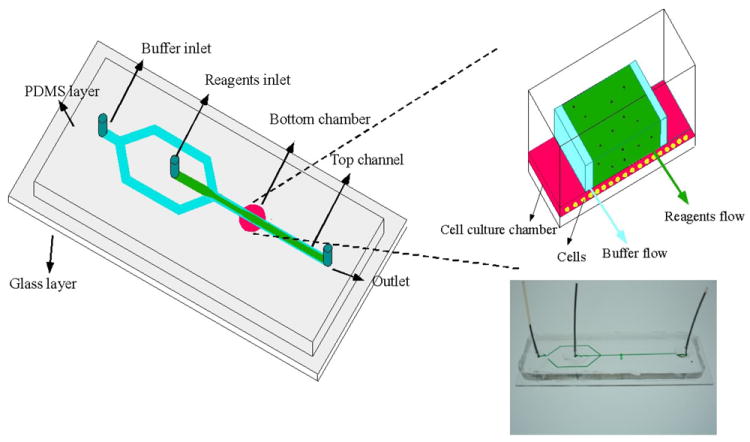
Schematic drawing of the chip. In the upper channel layer, buffer streams (blue) constrained regents (green) to the middle of the channel, and selectively treated cells in the chamber culture well directly beneath the regents. The inset to the right illustrates the flow scheme at the interface of the culture well and upper reagent channel. The main fluid channel was 350 μm in width, 40 μm in height and 3.5- 4 cm in length; the diameter of the culture chamber was 1.2 mm, and the height was 15 μm. The photograph on bottom right is an actual device with green food coloring loaded in the channel for visualization
2. Experimental
2.2.1 Microfluidics Fabrication
The microfluidic device is shown in Figure 1. The fluid flow channel was located above a round cell culture chamber, resulting in reduced levels of hydrodynamic shear on cells. Phosphate-buffered saline (PBS, pH = 7.4, Invitrogen, Grand Island, NY, USA) was introduced from the first chip inlet (Figure 1), which branched into two streams. The second inlet fed the center stream. This hydrodynamic focusing approach constrained reagents spatially. Reagents could be loaded in the side streams, with buffer or a second reagent in the center stream, if desired.
The device required the fabrication of two layers of polydimethylsiloxane (PDMS) (Dow Sylgard 184, Ellesworth adhesive, Washington, USA). PDMS films were cast against molds fabricated on silicon wafers patterned with SU-8 photoresist (Microchem, Newton, MA, USA). For the chamber, the photoresist was coated using a spin coater (4000 rpm for 30 s) on a silicon wafer to generate a 15 μm-high culture chamber. After development, the photoresist was heated to 100 °C for 30 min. For the fluid delivery channel, the photoresist was spin coated at 1000 rpm for 30 s, which were used to generate a 40 μm-high channel. By molding the PDMS against the master, the positive replicas with chamber and channels were fabricated. The main fluid channel had a width of 350 μm and a length of 3.5-4 cm. The diameter of the cell culture chamber was 1.2 mm. Holes were then punched through the PDMS to create inlet and outlet ports, and tubing was connected for fluid delivery. An irreversible seal was made between the PDMS films and a glass cover slide using a plasma cleaner (1min, 200w, 200mTorr O2, Harrick plasma, Ithaca, NY, USA).
2.2. Channel modification for cell attachment
After the fabrication processes, the microfluidic channels were modified for cell attachment. For adherent cell seeding, channels were rinsed with fibronectin (100 μg/mL in PBS, Invitrogen) by overnight incubation at 37°C. In cases where suspended cells were used, Biotin anti-CD71 (BD Biosciences, San Diego, CA, USA) was coated on the channel to anchor the cells. The coating procedures have been described previously [28-29].
2.3. Cell culture and Cell seeding
PC-3 Prostate cancer cells (CRL-1435), and Ramos cells (CRL-1596) were purchased from American Type Culture Collections and cultured in RPMI 1640 medium supplemented with 10% fetal bovine serum and 20 mL/L penicillin-streptomycin solution (Hyclone, Logan, UT). PC-3 cells were maintained in an incubator at 37°C and 5% CO2 atmosphere, and trypsinized and re-suspended in the PBS with cell densities varied between 105-106 cells/mL before use. Cells were delivered to the device by directly injecting them to the chamber using a syringe with sharp needle that could directly punch through PDMS chip. Cells were allowed to adhere for 3 hours in the fibronectin coated chip, or 10 minutes for antibody modified chips.
2.4. Experimental setup
The device was positioned on an inverted microscope (IX71, Olympus, Center Valley, PA, USA) with a CCD camera (Hamamatsu, Bridgewater, NJ, USA) to acquire images. The reagents and PBS were introduced with two syringes controlled by two syringe pumps. Cells were observed using a 10X or 4X objective. Epifluorescence excitation was provided by a 100W mercury lamp using filter sets appropriate for the dyes used. The images were further analyzed using ImageJ software. Details are presented in previous work [30-31].
For three-dimensional scanning of fluid flow, we used an inverted microscope (Olympus, IX81) equipped with a confocal spectral imaging system (Yokogawa CSUX spinning disk confocal system with a Photometrics Evolve 512 EMCCD camera). Rhodamine 110 and Alexa Fluor 568 were loaded from side streams and middle stream, respectively. Fluorescence excitation was achieved using argon ion laser with appropriate filters for excitation and collection of dye fluorescence. Confocal images were obtained by scanning from the bottom of chamber to the top of channel in the region of the channel and chamber in 0.2 μm z-steps. In order to visualize the chamber bottom effectively, cells were seeded in the channel before measurement. Images were analyzed in three dimensions using Slidebook software.
2.5. Flow characterization
Fluorescent dye was used to examine the diffusion between chip layers and to assess interfacial stability between laminar streams. By introducing Rhodamine 110 (10μM in PBS) into the middle reagent stream, various flow rates ranging from 0.1 mL/h to 1 mL/h were used for loading buffer and dye solution. The width of middle dye stream was measured at the boundaries where dye intensity decreased to 10% of the maximum fluorescence intensity.
2.6. Selective delivery of regents into cells
For controlled reagent delivery studies, Calcein AM (10 μg/mL in PBS buffer) and Mito Tracker Red (MTR, 10 μg/mL in PBS buffer), staurosporine (5 μM in PBS, BD Scienceces) were flowed over prostate cancer cells and ramos cells, respectively, by hydrodynamic focusing. Calcein AM and MTR were delivered for 15 mins. The dye streams were then replaced with buffer prior to microscope imaging. For drug delivery, staurosporine was flowed over the center of the culture chamber for 24 hours. Cell viability was tested after staurosporine exposure by staining cells with 10 μg/mL of Calcein AM and propidium iodide (PI) for 10mins.
3. Results and Discussion
3.1 Chip characterization
Spatially selective cell treatment relies on the boundaries between laminar streams. The boundaries, in the absence of mixing, define the exposure region in the culture chamber. The interfaces of the laminar streams were first visualized using a rhodamine 110 solution in the center stream. The laminar flow in the reagent delivery streams ensured minimal lateral mixing. However, when the reagent channel passes over the culture chamber, the interface changes and there is potential for turbulent flow to be induced, particularly in the z-axis [29]. If no mixing occurred, then the reagents would never reach the cells in the culture chamber; however, adherent cells and suspended cells were both affected by reagents in the overhead stream. Figure 2A shows the width of the reagent stream at 0.1 mL/h and 0.02 mL/h flow rates. When flow rate decreased to 0.02 mL/h, more diffusional mixing occurred.
Figure 2.
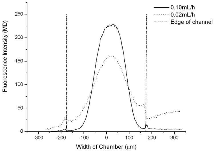

Reagent confinement analysis using rhodamine 110. A) Dye concentration distribution along the chamber at flow rate of 0.02 mL/h and 0.1mL/h. The reagent stream is seen to narrow when the flow rate of the channel increases. B) Width of middle stream at different flow rates of side buffer and middle dye streams. Increasing the side streams resulted in greater hydrodynamic focusing, while increasing the center stream lessened the degree of focusing.
In this simple two-layer device, there is some variation in the position of the reagent channel over the culture chamber from chip to chip. In our studies the reagent channel does not have to be positioned directly over the center of the culture chamber, but it cannot be far from the center. When the channel is not aligned near the chamber center, unstable fluid flow was observed (see Electronic Supplementary Information).
Both the center and side stream flow rates affect the area of cell exposure (Figure 2B). Increasing the middle stream flow rate resulted in wider reagent streams over the cell chamber. Conversely, larger outer stream flow rates resulted in narrower reagent streams for a given center stream flow rate. The width of the reagent stream over the cell chamber increased from 125 μm to 380 μm as the center stream flow rate was increased from 0.02 to 0.5 mL/h, when the buffer stream was set to 0.1 mL/h. At 0.5 mL/h the reagent stream width approaches the width of the reagent channel, and the reagent was no longer confined to the channel (i.e. the reagent diffused across the entire culture chamber).
Confocal fluorescence 3D scanning allowed us to visualize the distribution of reagents in the chip (Figure 3A & 3B). In this case, Rhodamine 110 was focused in the center stream, while the buffer streams were loaded with Alexa Fluor 568. After flow was allowed to equilibrate, three-dimensional scans of a portion of the culture chamber (limited by the microscope field of view) was imaged. The region of fluorescence overlap (yellow in color) is due to mixing between the streams. However, the central reagent (green) is clearly observed to remain in the center of the reagent channel and only affect cells in the center of the culture chamber. The buffer (red dye in this case) flows into the sides of the culture chamber, indicating that a two-reagent system can be realized in this type of chip.
Figure 3.
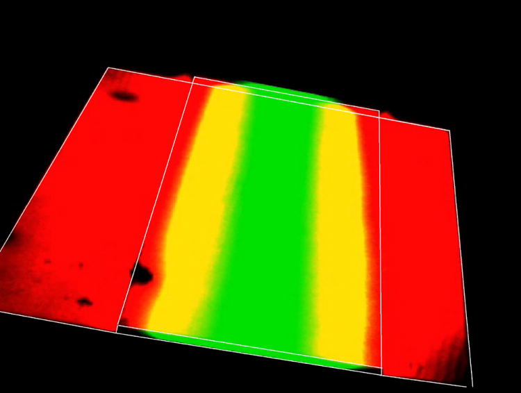
3D confocal fluorescence scanning of Rhodamine 110 (middle stream) and AlexaFluor568 (side streams). The chip outline is shown overlayed on the confocal images. The red dye diffuses into the culture chamber (only a portion of the culture chamber is shown in the microscope field of view), while the reagent stream (green) is confined to the center of the reagent channel.
3.2 Reduction in shear stress vs. a one-layer system
In any culture and analysis device, shear stress must be regulated to avoid introducing artifacts. Acceptable levels of shear stress can vary widely depending on cell type, various from less than 2 dyn/cm2 to 100 dyn/cm2 [22]. The reduction in shear in this chip was compared with the case when reagents flow directly over cells in a single-layer chip (the same chip design, but without a lower culture well, Figure 4). In this study, the buffer and central streams were 0.1 mL/h. The linear flow rate in single-layer chip was calculated to be 4.0mm/s in the channel that was 350 μm in width and 40 μm in height. When fluid flow into two-layer part, the channel height increased to 50 μm, and width of fluid were increased to 416 μm. Accordingly, the linear flow rate in two-layer system is 2.4mm/s. In the single-layer chip, cells were grown directly in a reagent channel lacking a lower culture chamber. The shear stress in the one-layer chip was calculated to be 6.0 dyn/cm2, which is not large enough to detach cells in these experiments, but still resulted in cell deformation. The shear stress in the two-layer system was calculated to be 2.7 dyn/cm2, owing in part to a change in the cross-sectional area of the channel and chamber. The shear stress in the sides of the culture chamber not directly above the reagent channel is expected to be lower, as there is no direct fluid flow. When prostate cancer cells are grown in a single-layer reagent chip (minus the lower, culture chamber), cells are shown to elongate in the direction of fluid flow (Figure 4A). When cells are grown in the two-layer chip, they retain their normal shape and are not affected by shear stress (Figure 4B). It is important to note that morphology was used only as an indicator of reduced shear, not as an indication of changes in shear stress on cells.
Figure 4.
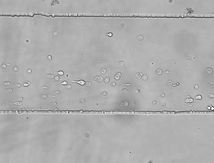
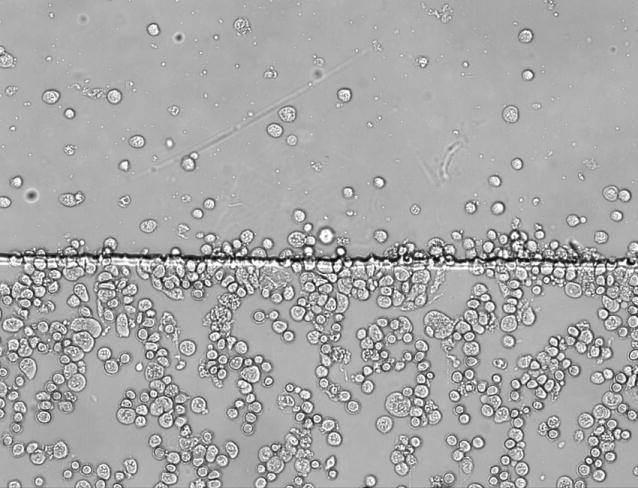
Cells anchored by anti-CD71 in a single-layer chip (A) and a two-layer reagent delivery chip (B). The reagent channel occupies the upper portion of the figure in each case. In the single-layer chip, the cells are observed to orient in the fluid flow (due to shear stress). In the two layer chip, cell growth is random in direction, indicating minimal influence from shear stress. The flow rate in both cases was 0.1 mL/h for all reagent streams. The scale is the same for both images.
3.3 Spatially-selective cell treatment
The key advantage of this microfluidic system is the ability to spatially control reagent delivery. Many applications, such as selective staining, drug delivery, or built-in controls can be envisioned with such a system. To demonstrate this concept, lymphocyte cells were simultaneously stained with Calcein AM and MitoTracker Red for 15 minutes (Figure 5). Cells exposed to the Calcein AM stream were stained green, while the cells under the MTR stream are stained red. There is some overlap area where cells were stained with both dyes, presumably due to diffusion. The overlap area is 9% of the total image area; the boundary region between the channel and the remaining culture chamber can be discarded during analysis. By controlling reagent flows from syringe pump, rapid switch between staining the entire cell population with one reagent and selectively treating only a portion of the cells can be achieved.
Figure 5.
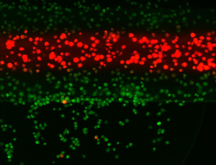
Spatially selective cell treatment in a two-layer culture system. Fluorescence images show that cells under the center stream are stained with MitoTracker Red, while cells in the remainder of the culture chamber serve are stained with Calcein-AM. The region of overlap (staining of both dyes) is 9% of the field of view.
3.4. Spatially selective apoptosis induction
It is possible to treat cells with a reagent selectively and conduct whole-chamber staining afterward. It is also possible to switch the reagent streams so that the center portion of the culture chamber is unaffected while the outer regions of the chip are exposed to reagents. In this case, the center reagent stream is a buffer while the outer streams contain the reagent of interest. In Figure 6, cells were selectively treated with staurosporine in the center of the culture well for 24 hours. In Figure 6A, staurosporine was flowed in the center reagent channel, so that only cells directly under the reagent streams were affected. In Figure 6B, the streams are switched so the center stream was only PBS. In this case, staurosporine affected cells that were not directly under the reagent stream (the remainder of the culture chamber). In both cases, after staurosporine treatment the entire chip was stained with calcein-AM and propidium iodide. In Figure 6A, the cells outside the reagent stream are viable (90% viability) while cells in the reagent stream, which were exposed to staurosporine, are dead (11% viability). In the opposite case of Figure 5B, cells in the reagent stream stain positively for calcein-AM (92% viability) while cells outside the reagent stream, exposed to staurosporine, stain positively for propidium iodide (1% viability). This chip is therefore not only capable of multi-step staining, long- or short-term reagent testing, and spatial control, but the system can be reversed to selectively stain different portions of the culture chip. It is important to note, however, that the flow in the remainder of the culture chamber is slower than in the reagent stream. Therefore, experiments where the reagents are delivered to the sides of the culture chamber will have a slower temporal response than when the reagent is delivered via the center stream. This chip is capable of local cell treatment via spatially-controlled reagent delivery, followed by global staining of the chip for analysis.
Figure 6.
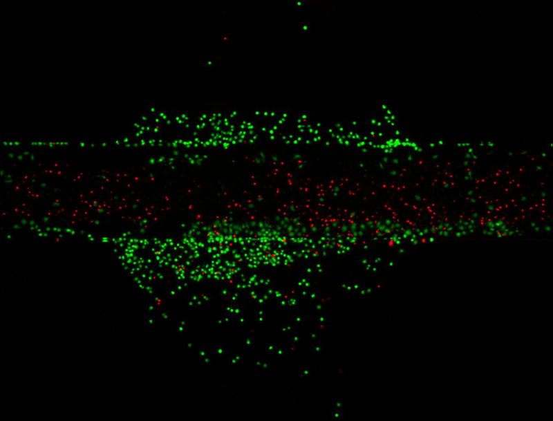
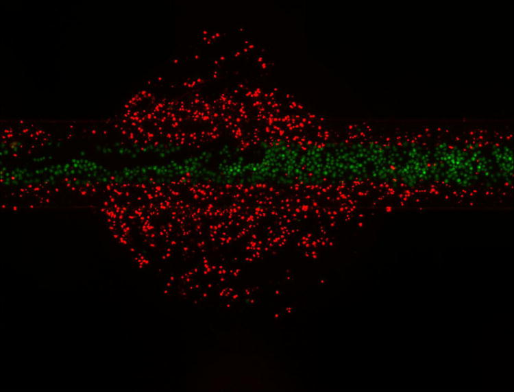
Selective reagent delivery can also be used in a step-wise fashion. Calcein-AM (green) and propidium iodide (Red) staining of Ramos cells selectively treated with staurosporine for 24 hours. Cells under the reagent stream (A) were dead (11% viable) while viability of the untreated cells is high (90% viable). The fluidic system can be reversed so that buffer is loaded in the center stream and reagent streams are on the outside of the reagent channel (B). In this case, the outer portions of the culture chamber are treated with staurosporine (1% viable) and the center of the channel, under the reagent stream, is healthy (92% viable). This chip can therefore be used to locally treat cells and then globally stain them for analysis.
Conclusion
A two-layer cell culture chip was used to generate spatially controlled flow. The design resulted in reduced shear stress, while providing new culture perturbation and analysis capabilities. By incorporating multiple laminar streams, reagents were confined to the reagent channel, and only cells under this portion of the chip were affected. Confocal microscopy showed that reagent confinement is stable. We have demonstrated that reagents can be delivered to the center of the culture chamber, the remainder of the culture well, or that two different reagents can be delivered to different parts of the culture simultaneously. It is also possible to selectively treat the culture and then stain the entire chip with multiple reagents, as was performed in a two-stain viability assay using staurosporine as the treatment reagent. In future work, we will refine the culture geometry to further reduce shear stress. In addition, on-chip valves can be incorporated to enable reagent switching and faster control of fluid flow and composition. It is also possible to incorporate membranes between the two chip layers to study membrane-based mass transport.
Supplementary Material
Highlights.
-
>
Microfluidic System for Spatially-Selected Reagent Delivery
-
>
Two-reagent studies possible
-
>
Drug delivery to cultured cells on a chip
Acknowledgments
This work was supported in part by grants from the National Institutes of Health (Grant RR025782 and GM10355 to DP and Grant AI077798 to WBB) and the Robert A. Welch Foundation (Grant D-1667 to DP).
Footnotes
Publisher's Disclaimer: This is a PDF file of an unedited manuscript that has been accepted for publication. As a service to our customers we are providing this early version of the manuscript. The manuscript will undergo copyediting, typesetting, and review of the resulting proof before it is published in its final citable form. Please note that during the production process errors may be discovered which could affect the content, and all legal disclaimers that apply to the journal pertain.
References
- 1.Velve-Casquillas G, Berre M, Piel M, Tran P. Nano Today. 2010;5:28–47. doi: 10.1016/j.nantod.2009.12.001. [DOI] [PMC free article] [PubMed] [Google Scholar]
- 2.zilkowska K, Kwapiszewski R, Brzozka Z. New J Chem. 2011;35:979–990. [Google Scholar]
- 3.Wlodkowic D, Cooper J. Anal Bioanal Chem. 2010;398:193–209. doi: 10.1007/s00216-010-3722-8. [DOI] [PubMed] [Google Scholar]
- 4.Wang F, Wang H, Wang J, Wang HY, Rummel PL, Garimella SV, Lu C. Biotechnol Bioeng. 2008;100:150–158. doi: 10.1002/bit.21737. [DOI] [PubMed] [Google Scholar]
- 5.Pappas D. Practical Cell Analysis. Wiley and Sons; 2010. [Google Scholar]
- 6.Paguirigan A, Beebe D. BioEssays. 2008;30:811–821. doi: 10.1002/bies.20804. [DOI] [PMC free article] [PubMed] [Google Scholar]
- 7.Chin L, Yu J, Fu Y, Yu T, Liu A, Luo K. Lab Chip. 2011;11:1856–1863. doi: 10.1039/c0lc00651c. [DOI] [PubMed] [Google Scholar]
- 8.Walker GM, Sai J, Richmond A, Stremler M, Chung CY, Wikswo JP. Lab Chip. 2005;5:611–618. doi: 10.1039/b417245k. [DOI] [PMC free article] [PubMed] [Google Scholar]
- 9.Groisman A, Lobo C, Cho H, Campbell J, Dufour Y, Stevens A, Levchenko A. Nat Methods. 2005;2:685–689. doi: 10.1038/nmeth784. [DOI] [PubMed] [Google Scholar]
- 10.Chung B, Flanagan L, Rhee S, Schwartz P, Lee A, Monuki E, Jeon N. Lab Chip. 2005;5:401–406. doi: 10.1039/b417651k. [DOI] [PubMed] [Google Scholar]
- 11.Lucchetta E, Lee J, Fu L, Patel N, Ismagilov R. Nature. 2005;434:1134–1138. doi: 10.1038/nature03509. [DOI] [PMC free article] [PubMed] [Google Scholar]
- 12.Takayama S, Ostuni E, LeDuc P, Naruse K, Ingber D, Whitesides G. Chem Biol. 2003;10:123–130. doi: 10.1016/s1074-5521(03)00019-x. [DOI] [PubMed] [Google Scholar]
- 13.Takayama S, Ostuni E, LeDuc P, Naruse K, Ingber D, Whitesides G. Nature. 2001;411:1016. doi: 10.1038/35082637. [DOI] [PubMed] [Google Scholar]
- 14.Sawano A, Takayama S, Matsuda M, Miyawaki A. Dev Cell. 2002;3:245–257. doi: 10.1016/s1534-5807(02)00224-1. [DOI] [PubMed] [Google Scholar]
- 15.Villa-Diaz LG, Torisawa Y, Uchida T, Ding J, Nogueira-de-Souza NC, O’Shea KS, Takayama S, Smith GD. Lab Chip. 2009;9:1749–1755. doi: 10.1039/b820380f. [DOI] [PMC free article] [PubMed] [Google Scholar]
- 16.Bathany C, Beahm D, Felske J, Sachs F, Hua S. Anal Chem. 2011;83:933–939. doi: 10.1021/ac102658h. [DOI] [PMC free article] [PubMed] [Google Scholar]
- 17.Ye N, Bathany C, Hua S. Lab Chip. 2011;11:1096–1101. doi: 10.1039/c0lc00350f. [DOI] [PubMed] [Google Scholar]
- 18.Wheeler AR, Throndset WR, Whelan RJ, Leach AM, Zare RN, Liao YH. Anal Chem. 2003;75:3581–3586. doi: 10.1021/ac0340758. [DOI] [PubMed] [Google Scholar]
- 19.VanDersarl JJ, Xuab AM, Melosh NA. Lab Chip. 2011;11:3057–3063. doi: 10.1039/c1lc20311h. [DOI] [PubMed] [Google Scholar]
- 20.Abhyankar VV, Lokuta MA, Huttenlocher A, Beebe DJ. Lab Chip. 2006;6:389–393. doi: 10.1039/b514133h. [DOI] [PubMed] [Google Scholar]
- 21.Ma L, Zhou C, Lin B, Li W. Biomed Microdevices. 2010;12:753–760. doi: 10.1007/s10544-010-9429-y. [DOI] [PMC free article] [PubMed] [Google Scholar]
- 22.Kim L, Toh Y, Voldman J, Yu H. Lab Chip. 2007;7:681–694. doi: 10.1039/b704602b. [DOI] [PubMed] [Google Scholar]
- 23.Haessler U, Kalinin Y, Swartz MA, Wu M. Biomed Microdevices. 2009;11:827–835. doi: 10.1007/s10544-009-9299-3. [DOI] [PubMed] [Google Scholar]
- 24.Lecault V, VanInsberghe M, Sekulovic S, Knapp D, Wohrer S, Bowden W, Viel F, McLaughlin T, Jarandehei A, Miller M, Falconnet D, White A, Kent D, Copley M, Taghipour F, Eaves C, Humphries K, Piret J, Hansen C. Nat Methods. 2011;8:581–586. doi: 10.1038/nmeth.1614. [DOI] [PubMed] [Google Scholar]
- 25.Liu K, Tian Y, Burrows SM, Reif RD, Pappas D. Anal Chim Acta. 2009;651:85–90. doi: 10.1016/j.aca.2009.08.007. [DOI] [PubMed] [Google Scholar]
- 26.Liu K, Pitchimani R, Dang D, Bayer K, Harrington T, Pappas D. Langumuir. 2008;24:5995–5960. doi: 10.1021/la8003917. [DOI] [PubMed] [Google Scholar]
- 27.Khanal G, Chung K, Solis-Wever X, Johnson B, Pappas D. The Analyst. 2011;136:3519–3526. doi: 10.1039/c0an00845a. [DOI] [PMC free article] [PubMed] [Google Scholar]
- 28.Wang K, Marshall MK, Garza G, Pappas D. Anal Chem. 2008;80:2118–2124. doi: 10.1021/ac702553w. [DOI] [PubMed] [Google Scholar]
- 29.Reif RD, Wang K, Pappas D. Anal Bioanal Chem. 2009;295:787–795. doi: 10.1007/s00216-009-3024-1. [DOI] [PubMed] [Google Scholar]
- 30.Liu Y, Bae S, Wang K, Hong J, Zhu Z, Tan W, Pappas D. Anal Chim Acta. 2010;673:95–100. doi: 10.1016/j.aca.2010.05.017. [DOI] [PubMed] [Google Scholar]
- 31.Nasir M, Mott DR, Kennedy MJ, Golden JP, Ligler FS. Microfluid Nanofluid. 2011;11:119–128. [Google Scholar]
Associated Data
This section collects any data citations, data availability statements, or supplementary materials included in this article.


