Abstract
A new method for the fabrication of microscale features in thermoplastic substrates is presented. Unlike traditional thermoplastic microfabrication techniques, in which bulk polymer is displaced from the substrate by machining or embossing, a unique process termed orogenic microfabrication has been developed in which selected regions of a thermoplastic surface are raised from the substrate by an irreversible solvent swelling mechanism. The orogenic technique allows thermoplastic surfaces to be patterned using a variety of masking methods, resulting in three-dimensional features that would be difficult to achieve through traditional microfabrication methods. Using cyclic olefin copolymer as a model thermoplastic material, several variations of this process are described to realize growth heights ranging from several nanometers to tens of microns, with patterning techniques include direct photoresist masking, patterned UV/ozone surface passivation, elastomeric stamping, and noncontact spotting. Orogenic microfabrication is also demonstrated by direct inkjet printing as a facile photolithography-free masking method for rapid desktop thermoplastic microfabrication.
Keywords: thermoplastic microfabrication, solvent swelling, microcontact printing, inkjet masking
INTRODUCTION
Thermoplastic polymers are attractive materials for the fabrication of a variety of microsystems, with applications including micro-optical components,(1) microcantilever chemical sensors,(2) microstructured biomimetic surfaces,(3, 4) and microfluidic chips.(5) Unlike elastomers such as polydimethylsiloxane (PDMS) commonly used for soft lithography,(6) thermoplastics offer a combination of excellent dimensional stability, good optical properties, low water absorption and gas permeability, low cost, and a range of bulk and surface properties. Thermoplastic microfabrication has been widely explored using replication methods including hot(7) or cold(8) embossing, injection molding,(9) and hot roller microprinting,(10) as well as serial fabrication methods such as direct laser machining(11, 12) and micromilling.(13) Each of these techniques involves the removal of material from desired regions within a thermoplastic substrate through thermal or mechanical mechanisms.
Here we report an entirely different approach to forming microscale features in thermoplastics termed orogenic microfabrication, wherein selected regions of a thermoplastic surface are raised from the bulk substrate through an irreversible solvent swelling mechanism. The term orogenic (“mountain forming”) is used to differentiate the process from conventional thermoplastic microfabrication methods based on material removal or displacement rather than surface growth. The orogenic process comprises selective exposure of a thermoplastic surface to a suitable organic solvent, resulting in controlled and irreversible swelling of the exposed regions. As the polymer expands due to solvent uptake, mobile polymer chains rearrange within the polymer matrix, resulting in permanent volume change within the plasticized regions even after the solvent has been fully removed from the bulk polymer. Unlike solvent-assisted microcontact molding,(14) a version of soft lithography in which solvent exposure is used to soften a thermoplastic substrate to enable replica molding from an elastomer template, and capillary imprint lithography,(15, 16) which employs thermally-induced capillary flow to reshape a polymer surface using a mold, orogenic microfabrication involves patterned surface growth to achieve the desired features. For amorphous non-polar thermoplastics, a chemical typically acts as a good solvent for the polymer when the cohesive energy densities for each molecular system are nearly equal.(17) The Hildebrandt solubility parameter, defined as the square root of the cohesive energy density,(18) provides a suitable metric for selecting an appropriate solvent for the orogenic process. Here we explore the process using cyclic olefin copolymer (COC), a class of thermoplastics commonly produced by chain copolymerization of cyclic hydrocarbon monomers such as norbornene and tetracyclododecane with ethene.(19) Cyclohexane was selected as a suitable organic solvent, with a Hildebrandt parameter that differs from that of COC by 6%.(20) By choosing a solvent/polymer system with a small difference in Hildebrandt parameters, solvent permeation is sufficient to allow controlled rearrangement of the polymer chains, without excessive solvation that could otherwise result in complete dissolution of the polymer surface.
Orogenic patterning through selective exposure of COC surfaces to cyclohexane vapor is explored using various masking methods, including direct photolithographic masking, selective chemical surface passivation, and both contact and non-contact pattern transfer methods. Depending on the masking technique employed, different microstructure morphologies can be achieved for the same initial mask patterns. In particular, direct photolithography using photoresist as a masking layer is found to result in solvent-initiated bulk swelling and concomitant polymer flow across the thermoplastic surface that expands pattern linewidths during vertical surface growth, limiting the achievable aspect ratios for the resulting features. In contrast, masking regions of the COC surface through selective exposure to a combination of UV light and ozone (UV/O3) generates polar oxygen-containing surface groups that effectively resist the absorption of nonpolar solvents into the polymer matrix, resulting in a reduction in pattern linewidths below the initially masked dimensions. Photolithography-free masking by microcontact printing and non-contact spotting is explored as a simple and low-cost approach to orogenic microfabrication using glycerol as a liquid-phase masking layer. Finally, inkjet printing is demonstrated as a facile approach to mask patterning enabling exceptionally rapid design-todevice cycle times. The combination of these methods enables fabrication of a range of unique microstructures that would be challenging to realize using traditional thermoplastic microfabrication techniques based on material removal rather than surface growth.
EXPERIMENTAL
Materials and Reagents
Methanol and 2-propanol were purchased from Fisher Scientific (Pittsburgh, PA). Cyclohexane and glycerol were purchased from Sigma-Aldrich (St. Louis, MO). Zeonor 1060R COC plates (2 mm thick) were procured from Zeon Chemicals (Louisville, KY). Wafer dicing tape was purchased from Semiconductor Equipment Corporation (Moorpark, CA).
Photoresist patterning
Thermoplastic plates were cut into 2 in square chips which were deburred to remove machining debris from the chip edges. The chips were sequentially sonicated in methanol, 2-propanol, and DI water for 5 minutes, then degassed overnight at 60 °C under vacuum. Shipley 1813 positive photoresist was spin-coated on the polymer chip surface to a thickness of approximately 1.5 µm, and patterned by contact photolithography through a chromium-coated glass plate mask using a UV flood exposure tool (PRX1000; Tamarack Scientific, Corona, CA). After exposure and photoresist development, the chips were rinsed with DI water, blown to dry with N2, and baked on a 60 °C hot plate for at least 8 hr to dehydrate the thermoplastic and densify the patterned photoresist.
UV/ozone passivation
Following photolithography, COC chips were loaded into a commercial UV/O3 exposure system (PSD-UV; Novascan Technologies, Ames, IA), and subjected to a 30 min exposure. After UV/O3 treatment, the polymer chips were submerged in methanol and sonicated for 1 min to remove photoresist, rinsed sequentially by 2-propanol and DI water, and dried at room temperature under a stream of N2.
Glycerol patterning
For microcontact printing with an elastomer stamp, a PDMS layer with 200 µm diameter circular posts was fabricated using a plastic mold formed by CNC milling. Glycerol was spin-coated onto a silicon wafer to a thickness of approximately 5 µm, and the PDMS stamp was pressed into the thin layer of glycerol and applied to the COC chip surface manually to transfer the patterned glycerol film. For masking by non-contact spotting, a single hair strand was dipped in glycerol and dragged along the COC chip surface to deposit discrete droplets with a distribution of diameters ranging from several microns to several hundred microns. Droplet diameters were measured optically prior to solvent exposure and post-exposure electron microscopy.
Inkjet printing
Inkjet printing was performed using a flatbed direct-to-substrate desktop printer (Direct Color Systems, Rocky Hill, CT) employing an Epson piezoelectric print head, with a proprietary ink based on a mixture of propyl glycol monomethyl ether and 2-butyl ethanol as a carrier. Although the printer supports thick substrates, a thin (100 µm) COC foil was used here to ensure future compatibility with standard paper feed systems in consumer-level inkjet printers.
Solvent exposure
The masked thermoplastic chips were positioned at the top of a sealed glass dish partially filled with cyclohexane, with the chip surfaces 5 cm from the liquid solvent. Wafer dicing tape was used to hold the chips in place while also serving to seal the opening of the dish. The cyclohexane was heated to 30 °C to generate an estimated equilibrium vapor pressure of 14 kPa.(21) For photoresist patterning, solvent exposure was performed in an enclosed oven to uniformly heat the entire assembly in order to reduce condensation of liquid solvent at the edges of the photoresist patterns. For solvent exposure using UV/O3, glycerol, and inkjet masks, the solvent dish was placed on a hot plate. After timed solvent exposure, the chips were promptly removed from the sealed chamber and dried under a stream of N2 to encourage removal of residual solvent from the bulk polymer. For photoresist masks, the resist was removed by a sequential methanol and DI water rinse. For glycerol and inkjet masks, the masking layers were removed by a DI water rinse.
RESULTS AND DISCUSSION
Photoresist masking
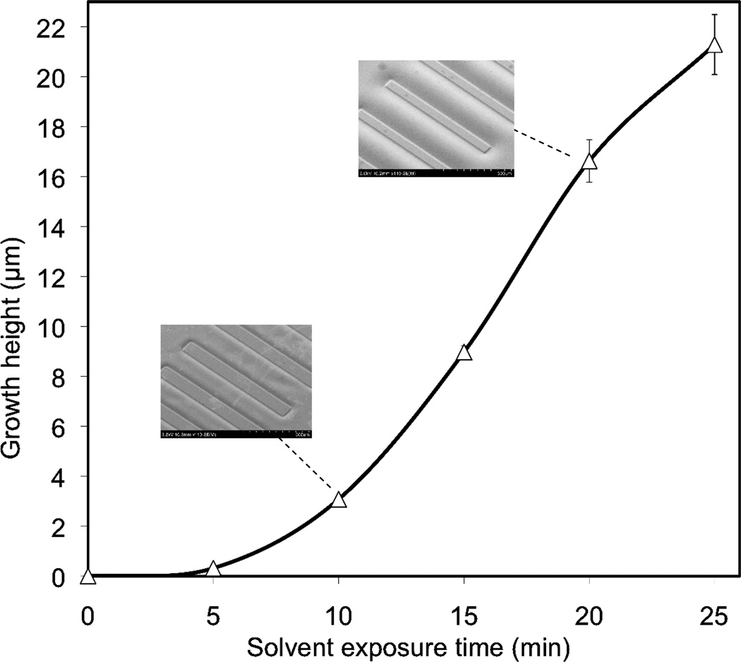
To evaluate the relationship between solvent exposure time and polymer surface growth, photoresist was used to mask regions of the COC surface from exposure to solvent vapor. Lines and spaces of varying width were patterned in a photoresist layer deposited on a set of COC chips, followed by timed vapor-phase exposure to the cyclohexane solvent. Measurements of polymer height changes were performed by stylus profilometry after orogenic growth. Like many glassy polymers, COC exhibits case II solvent diffusion characteristics,(22) in which a sharp solvent front separates the swollen and unexposed regions of the polymer. This phenomenon is largely due to a concentration-dependent viscous flow rate, and results in a linear rate of solvent intrusion into the polymer.(23) Using the COC/cyclohexane system, short solvent exposure times below 5 min were found to result in submicron growth heights, with gradually increasing grow rates (Figure 1). For solvation times between 5–25 min, a nearly constant growth rate consistent with case II diffusion was observed. For significantly longer solvent exposure times between 25–60 min (not shown), the growth rate was slightly reduced, with an average growth height of 51 µm achieved for the maximum tested exposure time of 60 min. These results were highly repeatable across multiple chips (n=5), with less than 10% variation in growth heights for all repeated experiments. Furthermore, the final heights of the solvated surfaces are very stable, with no measurable changes in geometry for chips stored at room temperature over a period of several weeks. Surface roughness of the solvated polymer was significantly reduced compared to the native surfaces (see Supporting Information and Figure S2), and no change in optical clarity or surface damage such as crazing was observed for any of the growth conditions explored here.
Figure 1.
Relationship between COC surface growth height and solvent vapor exposure time for patterns significantly larger than the growth height. Submicron heights can be reliably achieved for short (<5 min) exposures, while longer exposure times of 60 min yield growth heights above 50 µm (n=5). SEM images at two representative growth heights are shown inset.
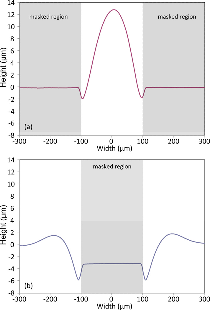
In addition to solvent exposure time, variations in mask dimensions can also affect the polymer growth height. A characteristic feature of the polymer swelling process is the formation of regions adjacent to the mask boundaries where polymer is first depleted and then piled up, resulting in distinct raised bulges near the mask edges. This behavior is clearly visible in the profilometry traces presented in Figure 2 for both positive (line) and negative (space) photoresist mask patterns. For large features, i.e. when the mask opening is significantly larger than the width of the pile-up zone, polymer swelling far from the mask boundaries is independent of pattern resolution and raised areas in the field exhibit growth heights consistent with Figure 1. However, when the mask opening approaches twice the width of the pile-up zone, the superimposed polymer fronts result in growth heights that can be significantly larger than those predicted for larger mask openings. For example, as shown in Figure 2, a COC chip patterned with a 200 µm wide photoresist space and exposed to solvent vapor for 10 min results in a peak height over 3 times larger than a patterned photoresist line of the same width.
Figure 2.
Profilometry traces revealing line and space cross-sections formed by 10 min orogenic growth of a COC surface masked with photoresist, using approximately 200 µm wide (a) positive (line) mask features and (b) negative (space) mask features. Narrow mask spaces exhibit larger growth than the field due to pile-up of polymer at the mask edges.
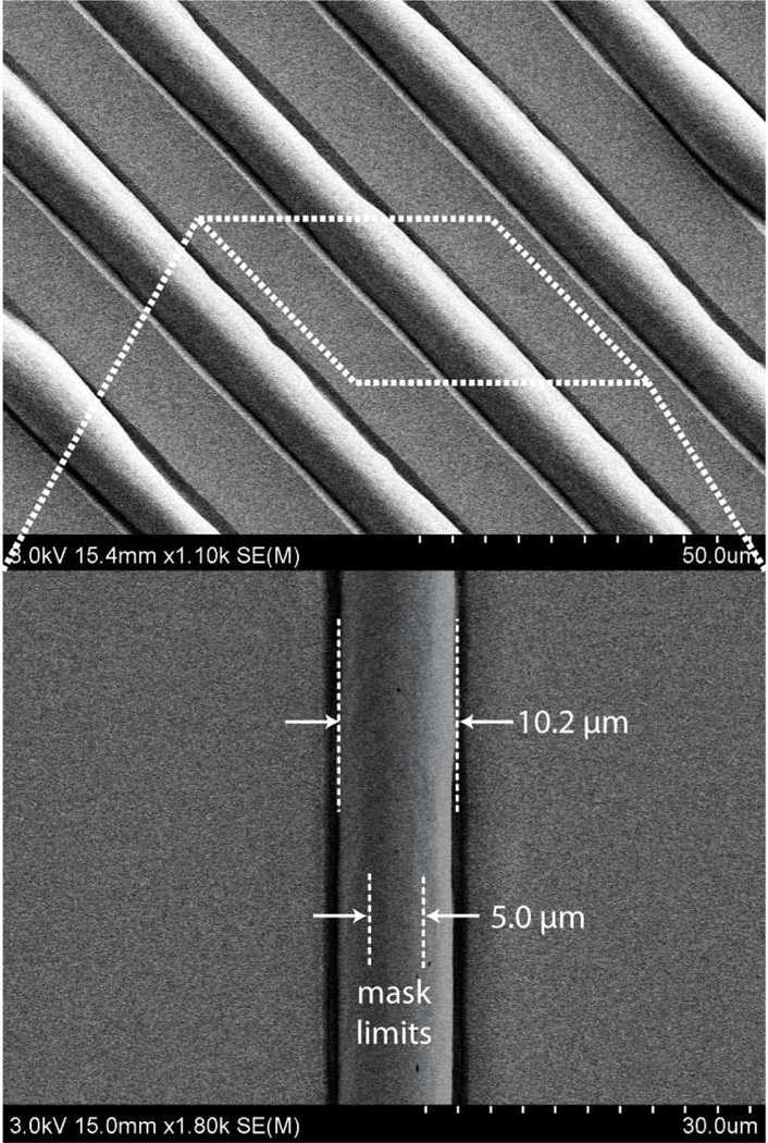
Minimum feature size is limited primarily by the desired growth height. Solvent is absorbed isotropically into the polymer matrix, and thus solvent is taken up by the polymer beneath the photoresist along the perimeter of the unmasked regions. As solvent is absorbed beneath the photoresist mask, the lateral dimensions of the resulting swelled polymer pattern increase, resulting in a minimum feature size of approximately twice the growth height. In this sense the process is similar to thermal oxidation of silicon, where the formation of a characteristic “bird’s beak” profile results from the growth of silicon dioxide beneath the edge of a nitride masking film. This phenomenon is more clearly seen for smaller masking patterns, as depicted in Figure 3 which shows the results of orogenic growth through a photoresist mask patterned with a periodic grid of 5 µm spaces. In this case, the raised features exhibit lateral expansion of approximately twice the growth height of 3.1 µm.
Figure 3.
Thermoplastic features resulting from orogenic growth through a photoresist mask patterned with a periodic grid of 5 µm spaces and growth height of 3.1 µm, revealing lateral solvent uptake by polymer beneath the masking layer.
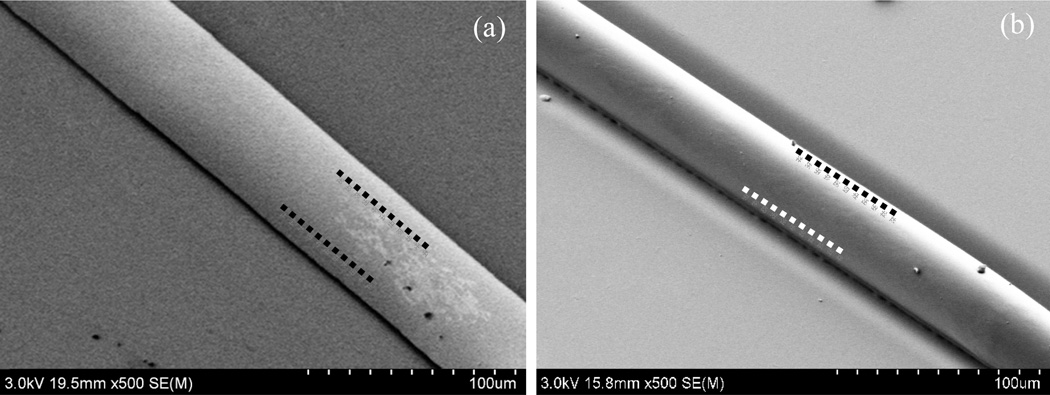
Regardless of the dimensions of the mask lines or spaces, as the growth height of the polymer surface increases, the solvated polymer eventually flows over the physical photoresist mask. As a result, the maximum growth height was found to be dependent on the patterned mask dimensions, with smaller mask openings resulting in lower growth heights due to lateral flow of a larger proportion of the solvated polymer. The transition from vertical growth to lateral flow over the mask occurs earlier for smaller mask openings due to earlier wetting of the photoresist surface by solvated polymer. Because the free polymer interface at the mask edge is driven to minimize its surface area by surface tension, it forms a curved boundary that tends toward a circular cross-section as more solvated polymer is extruded from the bulk substrate. For a given solvent exposure time, higher curvature occurs at smaller mask openings. As a result, solvated polymer is forced to contact the upper photoresist surface earlier in the growth process, wetting the photoresist and leading to polymer flow over the exposed surface. Thus predicting polymer swelling height and shape for the case of photoresist masking requires careful evaluation of this resolution-dependent transition between non-wetting and wetting growth modes. An example of a pattern defined using a 50 µm wide photoresist line and exposed to solvent vapor for 15 min is shown in Figure 4a. The orogenic feature expands beyond the initially-masked region, resulting in a final structure over 70 µm wide with significantly reduced height of the raised polymer surface. This flow of solvated polymer over the masking layer produces a region of polymer separated from the substrate by a 1.5 µm tall gap defined by the thickness of the photoresist mask.
Figure 4.
SEM images of orogenically-grown lines using 50 µm mask features by (a) direct photoresist masking, and (b) UV/O3 passivation. While lateral polymer flow leads to expansion of the line width for the case of photoresist masking, the UV/O3 masked line remains constrained by the oxidized surface. Approximate mask limits are shown with dotted lines in each case.
UV/O3 masking
As an alternative to masking with a physical photoresist layer, patterned orogenic growth can also be achieved by modifying the chemistry of the polymer surface to prevent solvent absorption in selected areas. While specific chemical groups can be attached to thermoplastics by methods such as photografting, a simpler approach to generating a solvent-resistant surface is through localized oxidation. We hypothesized that the presence of a dense layer of polar oxygen groups on the surface would prevent a non-polar solvent from penetrating into the bulk substrate. This concept was explored by exposing the COC surfaces to a controlled dose of UV/O3. The exposure of thermoplastics to UV/O3 is known to generate free radicals that can react with oxygen, resulting in surface species containing carboxyl, hydroxyl, or peroxide groups.(24) For example, we have previously reported that UV/O3 exposure of COC can more than triple the surface concentration of oxygen-containing species.(25) Indeed, initial tests revealed that UV/O3 treatment times longer than 20 min were sufficient to completely prevent the absorption of cyclohexane into the exposed polymer.
Solvent swelling of surfaces patterned by UV/O3 exhibit very different characteristics compared with the case of photoresist masking. Unlike the case of a physical photoresist mask, the high surface energy of the chemically-modified COC surfaces prevents flow of solvated polymer over the mask. In this case, the morphology of the raised features is defined by surface tension driven shaping of the solvated polymer. As a result of the lateral constraint during polymer growth, large growth heights may be achieved for small mask openings that would otherwise result in significant polymer flow over a physical photoresist masking layer. In principle, the swelling height and shape can be predicted given knowledge of the solvent exposure time, the resulting volume of solvated polymer, and mask dimensions. Because gravitational body forces acting on the solvated polymer are significantly smaller than surface tension at the size scales of interest in this work, the morphology of the resulting polymer structures may be determined based solely on surface tension driven shaping of the solvated material. As predicted using this simple model, sufficiently long solvent doses and small mask openings result in polymer features with nearly circular cross-sections. For example, when using linear 50 µm wide mask openings with a 15 min solvent dose, resulting in a total growth height of 43 µm due to polymer pile-up at the mask edges, structures with partial cylinder cross-sections are achieved (Figure 4b).
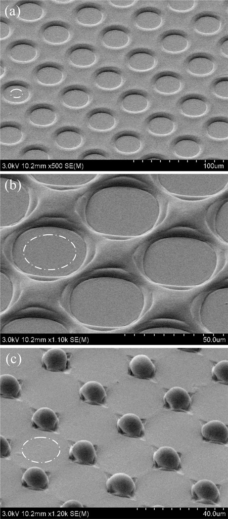
In addition to preventing flow of polymer over the oxidized field, it is surprising to note that UV/O3 masking results in final line widths that are smaller than the original mask openings. This phenomenon is independent of solvation time and surface growth height, and the resulting reduction in pattern width has been observed consistently for a variety of designs. For example, Figure 5a-c presents SEM images for a set of circular arrays with decreasing edge-to-edge spacing between adjacent array elements. During the 10 min solvent exposure used to define these features, the masked regions expand approximately 5 µm in all directions, thereby reducing the widths of raised features between the circles. For the case of 10 µm spacing shown in Figure 5c, the expanding effective mask areas have overlapped, resulting in an array of discrete posts. In all cases the transitions between the initial masked areas and final patterns are indistinguishable. The mechanism for the observed increase in masking may be related to solvent-induced migration of charged surface species generating during UV/O3 treatment. The ability to reproducibly form raised surface features below the resolution of the photolithographic mask represents an intriguing option for thermoplastic microfabrication.
Figure 5.
Arrays of circular mask features with progressively smaller edge-to-edge spacings of (a) 30 µm, (b) 20 µm, and (c) 10 µm following 10 min solvent exposure. The flat circular valleys passivated by UV/O3 exposure expand during orogenic growth, leading to the formation of discrete posts for the case of 10 µm spacing. Approximate sizes of the initial UV/O3 mask regions are shown in each image (dashed circles).
Pattern Transfer Masking
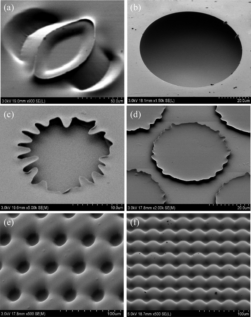
While photolithographic patterning using photoresist or UV/O3 masking layers can provide high resolution control over the microstructure geometry, the orogenic process is also compatible with direct masking using pattern transfer via selective deposition of a physical solvent barrier, for example by spotting or stamping a suitable material on the chip surface. Microcontact printing based on elastomeric stamping is an important soft lithography technique that offers the ability to achieve low-cost microscale and nanoscale patterns using a variety of materials with a simple master template, commonly fabricated from PDMS. When using substrates such as glass or silicon, microcontact printing can be used to transfer patterned monolayers to the surface with a minimum resolution limited only by the elastomer stamp itself. Unlike these common substrates used in microcontact printing which support the transfer of chemical monolayers, for example through covalent attachment to silanol or thiol groups, thermoplastics are relatively inert and do not present suitable chemical handles for monolayer anchoring. Furthermore, surface modifications to promote this functionality can potentially inhibit the desired solvent absorption within unmasked areas. As an alternate approach, the transfer of thick glycerol films by elastomeric stamping was investigated as a viable method for microcontact printing of a masking layer prior to orogenic growth. The high viscosity of glycerol and moderate hydrophobicity of the COC surface was found to prevent dispersion of the transferred glycerol patterns after spotting, with resolution limits on the order of 50 µm. However, removal of the stamp tended to create uneven distributions of glycerol on the COC due to surface tension effects. This behavior resulted in complex but reproducible structures following orogenic growth, such as the feature stamped with a circular PDMS post shown in Figure 6a.
Figure 6.
Orogenic features patterned in COC thermoplastic chips using different masking techniques: (a) glycerol microcontact printing using a PDMS stamp, (b) glycerol spotting, (c-d) photoresist masking using light field and dark field masks, and (e-f) UV/O3 masking using light field and dark field masks.
Although this capability could potentially be harnessed to realize unique three-dimensional thermoplastic microstructures, a mechanistic understanding needed to relate stamp geometry, non-uniformities in the distribution of transferred glycerol, and the resulting orogenic patterns is lacking. To achieve uniform patterns of well-defined features, non-contact spotting of glycerol droplets was explored as an efficient and flexible masking technique that avoids glycerol redistribution during microcontact printing. Droplets with diameters ranging from 5~100 µm were deposited on a COC chip and exposed to cyclohexane vapor for up to 20 min. Just as with photoresist masking, the solvated polymer increasingly encroached over the glycerol droplets with longer solvation times, resulting in nearly hemispherical chambers partially enclosed within the substrate (Figure 6b). It is notable that the smooth rim morphology achieved with non-contact spotting is very different from edges of features patterned using circular photoresist masks, with the latter case result in polytomous extrusions around the rim. Examples of these extrusions are shown in Figure 6c and 6d for the case of light field and dark field photoresist masking, respectively. For comparison, similar light and dark field features patterned by UV/O3 masking are presented in Figure 6e-f. In these latter cases, no encroachment of the solvated polymer into the masked regions is observed, consistent with the results described in Figure 5.
Inkjet printing
Inkjet printing is commonly used for the deposition of macroscale patterns of biological materials such as oligonucleotides(26) or proteins(27) for rapid microarray preparation. Here we have adapted standard inkjet printing technology for deposition a removable masking layer, consisting of dye or pigment components within an oil-based ink, to enable patterned orogenic growth of the deposition substrate. The use of an oil-based ink was dictated by the moderate hydrophobicity of common thermoplastics including COC, requiring a non-aqueous carrier to prevent the ink from beading on the polymer surface and losing printing resolution before drying. After orogenic growth, the ink is easily removed from the chip surface by brief sonication in water.
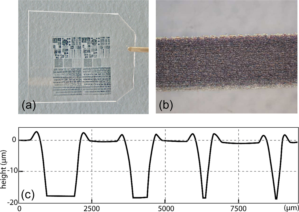
An image of a thin COC foil containing an inkjet printed mask design is shown in Figure 7(a), together with a micrograph of a 400 µm wide ink line on the foil surface in Figure 7(b). The ink used in this work exhibits no significant lateral dispersion over the chip surface and provides nearly uniform ink distribution over the patterned line. Variations in ink coverage near the edges of printed features are common, resulting in sloped sidewalls as apparent from the stylus profilometry traces in Figure 7(c) measured from a set of inkjet printed line features ranging in width from 100 µm to 400 µm following 15 min orogenic growth. The raised regions also exhibit distinct shoulders near the mask edges, similar to the results of photoresist masking shown in Figure 2. While the observed sidewall slope and overall resolution constraints of consumer-level inkjet printers limits the range of dimensions that can be realized with the inkjet masking method, this approach eliminates the need for direct photolithography or microcontact stamp preparation.
Figure 7.
(a) Inkjet printed COC film chip and (b) micrograph of a 400 µm wide line of oil-based ink on the COC surface showing uniform coverage and minimal dispersion. (c) Profilometry traces from a series of inkjet printed line features, 100–400 µm wide, following 15 min orogenic growth and removal of ink from the chip surface.
CONCLUSIONS
Overall, the orogenic process offers unique capabilities for patterning microscale and nanoscale features in rigid thermoplastics using a simple solvent swelling technique. The process is differentiated from traditional methods of thermoplastic patterning by the use of controllable solvent swelling rather than material removal or mechanical displacement to achieve a range of three-dimensional surface features. The surface growth process is compatible with multiple masking techniques, including direct photolithography, chemical surface modification, microcontact stamping, non-contact spotting, and inkjet deposition as demonstrated in this work. The selection of masking method is seen to have a significant impact on the resulting surface structure, with resolution limits, sidewall angles, and overall morphology affected by interactions between the mask layer and the solvent swelling process. A variety of unique features can be realized with different masking methods, with potential applications in the fabrication of thermoplastic microwell arrays, microfluidic systems, microoptical components, and beyond. The application of consumer-level inkjet printing for orogenic masking is particularly attractive for rapid manufacturing enabling concept-to-device cycle times in a true low-cost and scalable desktop process. Furthermore, the use of direct-to-substrate inkjet systems for mask deposition may be extended to the fabrication of complex micropatterns on non-planar thermoplastic substrates, and many of the masking methods explored in this work can be readily combined with more traditional approaches to thermoplastic microfabrication to further expand the range of patterning options for these materials. It should also be noted that while the orogenic process has been explored here using COC as a model thermoplastic material, the concept may be extended to other polymers with the selection of suitable solvents and exposure conditions.
Supplementary Material
ACKNOWLEDGMENTS
This research was supported in part by NIH grants R21EB011750 and R21EB009485, and by the DARPA N/MEMS S&T Fundamentals Program under grant no. N66001-1-4003 issued by the Space and Naval Warfare Systems Center Pacific (SPAWAR) to the Micro/nano Fluidics Fundamentals Focus (MF3) Center. Electron microscopy was performed with support from the University of Maryland Nanoscale Imaging, Spectroscopy, and Properties Laboratory (NISPLab).
Footnotes
Supporting Information Available: This information is available free of charge via the Internet at http://pubs.acs.org/.
REFERENCES
- 1.Cristea D, Obreja P, Kusko M, Manea E, Rebigan R. Polymer micromachining for micro- and nanophotonics. Materials Science and Engineering C. 2006;26:1049–1055. [Google Scholar]
- 2.McFarland AW, Colton JS. Chemical sensing with micromolded plastic microcantilevers. Journal Of Microelectromechanical Systems. 2005;14:1375–1385. [Google Scholar]
- 3.Lee Y, Park SH, Kim KB, Lee JK. Fabrication of Hierarchical Structures on a Polymer Surface to Mimic Natural Superhydrophobic Surfaces. Advanced Materials. 2007;19:2330–2335. [Google Scholar]
- 4.Schulte AJ, Koch K, Spaeth M, Barthlott W. Biomimetic replicas: Transfer of complex architectures with different optical properties from plant surfaces onto technical materials. Acta Biomaterialia. 2009;5:1848–1854. doi: 10.1016/j.actbio.2009.01.028. [DOI] [PubMed] [Google Scholar]
- 5.Becker H, Gärtner C. Polymer microfabrication methods for microfluidic analytical applications. Electrophoresis. 2000;21:12–26. doi: 10.1002/(SICI)1522-2683(20000101)21:1<12::AID-ELPS12>3.0.CO;2-7. [DOI] [PubMed] [Google Scholar]
- 6.Xia Y, Whitesides GM. Soft Lithography. Annual Review of Materials Science. 1998;28:153–184. [Google Scholar]
- 7.Martynova L, Locascio LE, Gaitan M, Kramer GW, Christensen RG, MacCrehan WA. Fabrication of plastic microfluid channels by imprinting methods. Analytical Chemistry. 1997;69:4783–4789. doi: 10.1021/ac970558y. [DOI] [PubMed] [Google Scholar]
- 8.Xu JD, Locascio L, Gaitan M, Lee CS. Room-temperature imprinting method for plastic microchannel fabrication. Anal. Chem. 2000;72:1930–1933. doi: 10.1021/ac991216q. [DOI] [PubMed] [Google Scholar]
- 9.McCormick RM, Nelson RJ, Alonso-Amigo MG, Benvegnu DJ, Hooper HH. Microchannel electrophoretic separations of DNA in injection-molded plastic substrates. Analytical Chemistry. 1997;69:2626–2630. doi: 10.1021/ac9701997. [DOI] [PubMed] [Google Scholar]
- 10.Ng SH, Wang ZF. Hot roller embossing for microfluidics: process and challenges. Microsystem Technologies. 2008;15:1149–1156. [Google Scholar]
- 11.Roberts MA, Rossier JS, Bercier P, Girault H. UV Laser Machined Polymer Substrates for the Development of Microdiagnostic Systems. Analytical Chemistry. 1997;69:2035–2042. doi: 10.1021/ac961038q. [DOI] [PubMed] [Google Scholar]
- 12.Wang L, Zhang D, Wen Z, Zhang H. Micro-fabrication and monitoring of three-dimensional microstructures based on laser-induced thermoplastic formation. Microscopy Research and Technique. 2009;72:717–722. doi: 10.1002/jemt.20722. [DOI] [PubMed] [Google Scholar]
- 13.Chen CF, Liu J, Hromada LP, Tsao CW, Chang CC, DeVoe DL. High-pressure needle interface for thermoplastic microfluidics. Lab on a Chip. 2009;9:50–55. doi: 10.1039/b812812j. [DOI] [PubMed] [Google Scholar]
- 14.Kim E, Xia Y, Zhao X-M, Whitesides GM. Solvent-Assisted Microcontact Molding: A Convenient Method for Fabricating Three-Dimensional Structures on Surfaces of Polymers. Advanced Materials. 1997;9:651–654. [Google Scholar]
- 15.Suh KY, Lee HH. Capillary Force Lithography: Large-Area Patterning, Self-Organization, and Anisotropic Dewetting. Advanced Functional Materials. 2002;12:405–413. [Google Scholar]
- 16.Suh K-Y, Park MC, Kim P. Capillary Force Lithography: A Versatile Tool for Structured Biomaterials Interface Towards Cell and Tissue Engineering. Advanced Functional Materials. 2009;19:2699–2712. [Google Scholar]
- 17.Brydson J. Plastic Materials. Oxford: Butterworth-Heinemann; 1999. [Google Scholar]
- 18.Hildebrandt J, Scott R. The solubility of non-electrolytes. New York: Reinhold; 1949. [Google Scholar]
- 19.Shin JY, Park JY, Liu C, He J, Kim SC. Chemical structure and physical properties of cyclic olefin copolymers. Pure and Applied Chemistry. 2005;77:801–814. [Google Scholar]
- 20.Tsao C-W, DeVoe DL. Bonding of thermoplastic microfluidics. Microfluid. Nanofluid. 2008;6:1–16. [Google Scholar]
- 21.Cruickshank AJB, Cutler AJB. Vapor pressure of cyclohexane, 25 to 75 C. J. Chem. Eng. Data. 1967;12:326–329. [Google Scholar]
- 22.Wallow TI, Morales AM, Simmons BA, Hunter MC, Krafcik KL, Domeier LA, Sickafoose SM, Patel KD, Gardea A. Low-distortion, high-strength bonding of thermoplastic microfluidic devices employing case-II diffusion-mediated permeant activation. Lab on a Chip. 2007;7:1825–1831. doi: 10.1039/b710175a. [DOI] [PubMed] [Google Scholar]
- 23.Thomas NL, Windle AH. A theory of case II diffusion. Polymer. 1982;23:529–542. [Google Scholar]
- 24.Wei S, Vaidya B, Patel AB, Soper SA, McCarley RL. Photochemically patterned poly(methyl methacrylate) surfaces used in the fabrication of microanalytical devices. The Journal of Physical Chemistry B. 2005;109:16988–16996. doi: 10.1021/jp051550s. [DOI] [PubMed] [Google Scholar]
- 25.Tsao CW, Hromada L, Liu J, Kumar P, DeVoe DL. Low temperature bonding of PMMA and COC microfluidic substrates using UV/ozone surface treatment. Lab on a Chip. 2007;7:499–505. doi: 10.1039/b618901f. [DOI] [PubMed] [Google Scholar]
- 26.Lausted CG, Warren CB, Hood LE, Lasky SR. Printing your own inkjet microarrays. Methods in Enzymology. 2006;410:168–189. doi: 10.1016/S0076-6879(06)10008-7. [DOI] [PubMed] [Google Scholar]
- 27.McWilliam I, Chong Kwan M, Hall D. Inkjet printing for the production of protein microarrays. Methods In Molecular Biology. 2011;785:345–361. doi: 10.1007/978-1-61779-286-1_23. [DOI] [PubMed] [Google Scholar]
Associated Data
This section collects any data citations, data availability statements, or supplementary materials included in this article.


