Abstract
Droplet microfluidics performed in poly(methylmethacrylate), PMMA, microfluidic devices resulted in significant wall wetting by water droplets formed in a liquid-liquid segmented flow when using a hydrophobic carrier fluid, such as perfluorotripropylamine (FC-3283). This wall wetting led to water droplets with non-uniform sizes that were often trapped on the wall surfaces leading to unstable and poorly controlled liquid-liquid segmented flow. To circumvent this problem, we developed a two-step procedure to hydrophobically modify the surfaces of PMMA and other thermoplastic materials commonly used for making microfluidic devices. The surface modification route involved the introduction of hydroxyl groups by oxygen plasma treatment of the polymer surface followed by a solution phase reaction with heptadecafluoro-1,1,2,2–tetrahydrodecyl trichlorosilane dissolved in the fluorocarbon solvent FC-3283. This procedure was found to be useful for the modification of PMMA and other thermoplastic surfaces, including polycyclic olefin copolymer (COC) and polycarbonate (PC). Angle-resolved X-ray photoelectron spectroscopy indicated that the fluorination of these polymers took place with high surface selectivity. This procedure was used to modify the surface of a PMMA droplet microfluidic device (DMFD) and was shown to be useful to reduce the wetting problem during the generation of aqueous droplets in a perfluorotripropylamine (FC-3283) carrier fluid and could generate stable segmented flows for hours of operation. In the case of the PMMA DMFD, oxygen plasma treatment was carried out after the PMMA cover plate was thermally fusion bonded to the PMMA microfluidic chip. Because the appended chemistry to the channel wall created a hydrophobic surface, it will accommodate the use of other carrier fluids that are hydrophobic as well, such as hexadecane or mineral oils.
Introduction
Droplet microfluidics—also called two-phase flows, liquid-liquid segmented flows or plug-based microfluidics—consists of a stream of nano- to picoliter-sized droplets or plugs generated in a stream of an immiscible carrier liquid.1-4 High rates of droplet generation, on the order of a few thousand droplets per second, can be achieved.5 These droplets can also be manipulated, for example fusing them with other droplets1 so that the contents of the two droplets mix rapidly by chaotic advection.6 Some of the advantages of droplet flow over continuous flow include low reagent consumption and improved heat transfer7 due to the high surface-to-volume ratio of the droplets. The presence of specific reagents within the droplets can limit their hydrodynamic dispersion.8,9 Further, the interaction of shear and interfacial forces at the droplet interface with the carrier fluid can induce recirculation of fluid inside the droplet, as well as the carrier fluid, resulting in rapid mixing of droplet contents.7
Each droplet can act as an independent reactor. This characteristic, along with low dispersion and fast mixing, has been shown to be useful in a number of compelling applications such as continuous segmented flow polymerase chain reactions (PCRs),10, 11 blood group sorting,12 and fabrication of Janus,13 ternary14 and magnetic hydrogel particles.15 Also, droplet microfluidics has been shown to be useful to optimize protein crystallization conditions.16 Furthermore, the capability to produce uniform droplets and their rapid mixing8, 17, 18 has lead researchers to explore its potential to replace conventional micro-titer plates for high-throughput screening in drug discovery applications.19
Initially, microfluidic devices were predominately made from glass substrates.20 Glass devices prepared using lithographic methods adopted from the microelectronics industry facilitated the production of devices with excellent dimensional quality. Glass-based devices also offered high optical clarity and compatibility with many organic solvents, such as those used as carrier fluids in segmented flows to support the production of aqueous droplets. Later, polydimethylsiloxane, PDMS, was introduced for the fabrication of microfluidic devices,20, 21 and it is now widely used for the fabrication of droplet microfluidic devices due to the ease of preparation.1 Glass and PDMS-based devices have well defined surface chemistries that can be employed to modify the surface properties of the material making these surfaces wettable to an organic carrier fluid frequently used in droplet microfluidics. Unfortunately, PDMS and glass microfluidic devices are not suitable for the large-scale production of devices for a variety of reasons.22
Development of droplet microfluidic devices using thermoplastics as a substrate, which can be replicated from mold masters using hot embossing or injection molding, lends itself to the high production of microfluidic chips with high fidelity and at low-cost, unique to this substrate material.23, 24 Common thermoplastic materials used for microfluidics includes, but not limited to, poly(methylmethacrylate), PMMA, and cyclic olefin copolymer, COC, have excellent optical properties (low autofluorescence) and are readily shaped using techniques such as hot embossing or injection molding. In addition, polymers have a diverse array of surface chemistries with some exhibiting poor wettability or even incompatibility with many of the common hydrophobic carrier fluids, which can generate unstable segmented flows.25 This limitation could possibly be minimized by appending a hydrocarbon, especially those that are fluorinated, to the surface of the microfluidic channels to make them more wettable by the carrier fluid.25 Several methods have been reported in the literature to introduce hydrophobic fluorinated layers on polymeric surfaces and these include direct fluorination using fluorine gas,26 plasma polymerization27 and coatings.28 However, such procedures require careful handling of reactive gases.
A simpler approach to realize surface fluorination of materials is surface chemical modification using a perfluoro-silane. For example, attachment of silane-containing moieties onto polymer surfaces has been reported using both solution and gas-phase routes.29-31 For solution-based silane modification, the commonly used solvents are toluene and chlorinated hydrocarbons. Toluene can be used only for a select group of polymers, and chlorinated hydrocarbons can cause swelling or dissolve polymer substrates, making such a route unfeasible for the surface modification of a number of polymers. Hence, reactions of silanes with polymer surfaces are most commonly carried out in the gas phase.25, 29-31 However, gas-phase reactions can often lead to multilayers of silanes,30 thereby leading to a lack of control over the thickness of the silane layer.
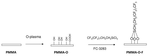
This paper reports a simple surface modification procedure for polymeric droplet microfluidic devices (DMFDs) that lead to the generation of stable aqueous droplet trains in a continuous liquid-liquid segmented flow system. The general strategy involved an oxygen plasma treatment that introduced oxygen containing groups onto the polymer surface, such as hydroxyl groups, that were then used as a functional scaffold to which silanizing reagents were covalently attached to the polymer surface.30 In this work, we used a perfluorinated silane dissolved in a perfluorinated solvent to form fluorinated layers on a variety of polymer substrates used to construct microfluidic devices. The modification protocol did not detrimentally affect the topography of the underlying polymer substrate, but yet was a good solvent for the perfluoro-silane reaction. The reported method was shown to be useful for the surface selective incorporation of perfluoro-silane on a number of polymer films as well as polymers shaped via molding into fluidic structures.
Experimental
Materials
PMMA sheets (250-μm thick, ME303005) were purchased from Goodfellow, Oakdale, PA. COC sheets (250-μm thick) were purchased from Topas, Florence, KY. Polycarbonate, PC, sheets (500-μm thick) were purchased from SABIC polymer shapes, New Orleans, LA. PMMA sheets (GE EXAN 9034, 2.36-mm thick) were obtained from Modern Plastics, Bridgeport, CT. FC-3283, perfluorotripropylamine, was obtained from 3M Corporation, St-Paul, MN. Heptadecafluoro-1,1,2,2-tetrahydrodecyltrichlorosilane (CF3(CF2)7CH2CH2SiCl3) was obtained from Gelest. 1H, 1H, 2H, 2H-Perfluorooctanol, 97%, was obtained from Alfa Aesar, Ward Hill, MA. 5-(4,6-dichlorotriazinyl)aminofluorescein, DTAF, was obtained from Molecular Probes and dichloromethane was obtained from Sigma-Aldrich. Instrumentation. Sessile water drop contact angle measurements were obtained using a VCA 2000 contact angle system equipped with a CCD camera (VCA, Billerica, MA). For each measurement, 2 μL of deionized water (18 M cm) was placed on the polymer surface using a syringe and the contact angle of the water droplet was measured immediately using the software provided by the manufacturer. The measurements were repeated at least five times at separate positions on a given substrate and the average values were reported.
X-ray photoelectron spectra (XPS) were acquired using a Kratos AXIS 165 system with a monochromatic AlKα source and a hemispherical electron energy analyzer as reported earlier.32 The pressure in the analyzing chamber was less than 3 × 10⁻⁹ Torr. The normal-emission, angle-integrated, high-resolution scans with 15–20 eV windows and pass energy of 40 eV were acquired for the C1s, O1s, F1s and Si2p regions. The reported binding energies were based on the analyzer energy calibration (Au 4f measured at 84.0 eV for all samples). The peaks in the high-resolution elemental spectra were fit using the software supplied with the instrument. A linear background was used for the data processing.
Scanning force microscopy (SFM) was used to determine the surface roughness and topographies of the unmodified, oxygen plasma-treated and perfluorosilane-treated polymer surfaces using a Digital Instruments Nanoscope III multimode scanning force microscope in noncontact force mode (Tapping mode). The images were treated by use of the flatten algorithm of the Nanoscope software. Root-mean-square (rms) roughness values were calculated using the instrument software.
Ellipsometric thicknesses were determined using a Rudolph Research Auto EL III ellipsometer possessing a He-Ne laser (632.8 nm) at an angle of incidence of 70°.32 Six separate points were measured on each sample and the readings were then averaged and reported with an error of ±1 standard deviation unit. The optical constants of bare Au were obtained from Au surfaces that were cleaned by exposure to a low-pressure mercury UV lamp for 30 min (so-called UV Ozone method)33 and washed with ethanol, followed by rinsing with deionized water and dried in a stream of dry nitrogen. Then, the cleaned Au slides were coated with a thin layer of PMMA by spin coating a 2% (w/v) PMMA/CH2Cl2 solution onto the slides. The thickness of the PMMA coating was calculated using the optical constants of Au and a parallel three-layer model34 with an assumed refractive index of 1.45 for the PMMA layer.35 The PMMA-coated Au slides were then immersed in FC-3283 for 2 h. The slides were removed and washed with FC-3283, isopropanol, 50% (v/v) isopropanol/DI water, DI water, and finally dried under a flow of nitrogen. Following this procedure, the thickness of the PMMA layer was once again measured.
Photographs of droplet wetting/non-wetting on PMMA surfaces were obtained using an Axiovert 200M microscope (Carl Zeiss, Thornwood, NY). PMMA microfluidic devices were fixed onto a programmable motorized stage of the microscope and video images were collected during each experiment at 30 frames per second (fps) using a monochrome CCD camera (JAI CV252, San Jose, CA).36
Surface fluorination
Surface fluorination was carried out using a two-step procedure. In the first step, the polymer surface was treated with an oxygen plasma and in the subsequent step, the oxidized polymer surface was treated with heptadecafluoro-1,1,2,2–tetrahydrodecyl trichlorosilane (HFTTCS). Oxygen plasma treatment was carried out using an RF (13.56 MHz) plasma reactor system (PDC-3XG, Harrick Plasma, Ithaca, NY) at 30 W. In the second step, the oxygen plasma-modified polymers were treated for 2 h with a 1 mM solution of heptadecafluoro-1,1,2,2–tetrahydrodecyl trichlorosilane in FC-3283. The surfaces were rinsed sequentially with FC-3283, isopropanol, 50% (v/v) isopropanol/water mixture and finally with water. Then, the modified surfaces were dried under a flow of dry nitrogen. Microchip fabrication. All microfluidic devices were formed by hot embossing using a micromilled brass molding tool.37 The mold master with the fluidic features was micromachined on a 4.75″ diameter brass substrate (Alloy 353, McMaster-Carr, Atlanta, GA) using a KERN MMP 2522 (KERN Micro- und Feinwerktechnik GmbH, Murnau-Westried, Germany) micromilling machine. The brass molding tool was used to thermoform chips in PMMA sheets using hot embossing (HEX02, JENOPTIK Mikrotechnik, Jena, Germany). After post-processing, including cutting the chips and drilling holes at the inlet and outlet reservoirs of the devices, they were cleaned using the following sequence of events; soaked in a mild detergent solution (1% (v/v), 5 min); ultrasonic agitation (2 min) to remove the organic lubricant used to assist in demolding and rinsed with deionized water. After machining and cleaning, the microfluidic devices were dried at 95°C (20 min) in a temperature-controlled oven and thermal fusion bonded to a 250-μm thick PMMA cover plate at 104°C for 20 min.
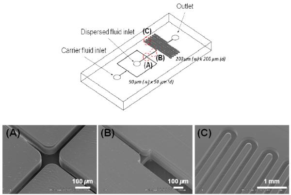
The design of the fabricated droplet generation devices is shown in Figure 1. Capillary tubes with a 175-μm inner diameter (1577 PEEKTM tube, Upchurch Scientific Inc., Oak Harbor, WA) were connected to the access holes of the device and sealed with epoxy (5-minute Epoxy, Devcon, Danvers, MA). The cross-sectional dimensions of the injection channels were 50 μm × 50 μm with a test channel containing dimensions of 200 × 200-μm. The diameter of the droplet generated at the cross-junction was larger than the width of the injection channels. Expanding the cross sectional area from the injection (50 μm × 50 μm) to the test (200 μm × 200 μm) channels enabled observations of the aqueous spherical droplets without contact with the channel walls and clear visualization of possible wetting.
Figure 1.
The design of the PMMA microfluidic chip used to generate aqueous droplets is shown in the upper panel. In the lower panel are SEMs of three different domains of the microfluidic device; the cross-junction (A), the expansion from the 50 μm × 50 μm injection channel into the 200 μm × 200 μm test channel (B) and the serpentine test channel (C).
Liquid-liquid segmented flow experiments
Liquid-liquid segmented flow experiments were carried out using a droplet microfluidic device as shown in Figure 1. FC-3283 (oil) containing 10% (v/v) nonionic fluoro-soluble surfactant, 1H, 1H, 2H, 2H-Perfluorooctanol (PFO), was introduced into the carrier fluid inlet (Figure 1) and deionized water was introduced into the dispersed fluid inlet (Figure 1). The water stream was combined with the immiscible fluorocarbon oil in two directions that were perpendicular to its path at the cross-junction as shown in Figure 1A. A combination of shear and interfacial forces at the interface between the water and oil streams generated continuous mono-dispersed droplets or plugs in the central channel past the cross junction. This stream of droplets in the carrier oil expanded into the test channel as shown in Figure 1B and traveled through a serpentine channel (see Figure 1C). Observations of the droplet flow at three different locations within the test channel were carried out for both unmodified and modified polymer microchannels.
Results and Discussion
We first attempted to use gas-phase reactions with HFTTCS to fluorinate a PMMA surface. Oxygen plasma-treated PMMA surfaces were exposed to HFTTCS vapor for 2 h so as to generate the fluorinated surface. These reactions produced a white film on the PMMA surface possessing water contact angles >145°. PMMA surfaces that were not plasma treated and exposed to HFTTCS vapors for 2 h also had a white film coating with a water contact angle >145°. These observations indicated that the high water contact angle was due to physisorbed HFTTCS.
We next investigated whether the fluorocarbon liquid FC-3283 could be used as a solvent for the fluorination reaction using PMMA as the substrate material. We found that heptadecafluoro-1,1,2,2–tetrahydrodecyl trichlorosilane was soluble in FC-3283. Then, we tested whether FC-3283 was compatible with PMMA. This was done by preparing a thin layer of PMMA on a clean Au slide prepared by spin coating PMMA dissolved in dichloromethane on the Au slide with subsequent drying of the slide in an oven at 60 °C for 2 h (ellipsometric film thickness = 48.1 ±1.2 Å). Then, the PMMA-coated Au slide was immersed in an FC-3283 solution for 2 h, washed with FC-3283, isopropanol, 50% (v/v) isopropanol/water mixture and rinsed with water and finally dried in dry nitrogen (PMMA layer thickness = 48.5 ±1.5 Å). The thickness of the PMMA layer did not change as a result of subjecting it to the FC-3283 solution indicating that this solution was compatible with the PMMA substrate.
Fluorination of planar PMMA surfaces
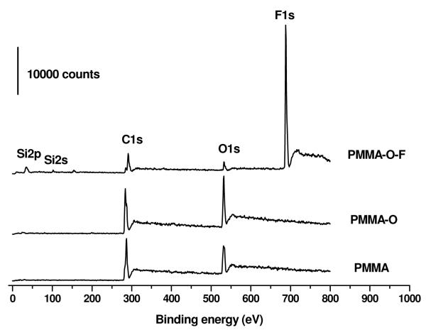
To initially evaluate the two-step fluorination procedure we used planar PMMA films, which could be interrogated by a variety of surface characterization tools such as XPS. The modification chemistry is shown in Scheme 1. The first step involved treating the PMMA films with an oxygen plasma for 30 s; we refer to this functional material as PMMA-O, which introduced polar oxygen-containing functional groups—including hydroxyl groups—onto the surface. The X-ray photoelectron spectra of PMMA and PMMA-O surfaces showed the expected C1s and O1s peaks, Figure 2. The O1s/C1s ratio at a 90° take-off angle was 0.361 for the PMMA-O surface compared to 0.309 for native PMMA indicating the incorporation of oxygen-containing functional groups.38,39
Scheme 1.
Reaction scheme used for the fluorination of various polymer surfaces using PMMA as an example in this depiction.
Figure 2.
X-ray photoelectron survey spectra of PMMA, PMMA-O and the HFTTCS-treated PMMA (PMMA-O-F) surfaces. These spectra were recorded using a monochromatic AlKα X-ray source at 150 W X-ray beam power with 80 eV pass energy. The thickness of the PMMA film was 250 μm.
In the second step, the activated polymer surface was treated with a 1 × 10⁻³ M solution of HFTTCS in FC-3283 for 2 h; these surfaces are referred to as PMMA-O-F. This treatment step did not affect the transparency of the PMMA substrate and the resulting surface exhibited a water contact angle of 119° ± 1°. This value is similar to the contact angle value reported for a monolayer of HFTTCS on silica supported on a silicon wafer.40 A control PMMA substrate (i.e., without oxygen plasma treatment, referred to as PMMA-F) was also treated with a 1 × 10⁻³ M solution of HFTTCS in FC-3283 for 2 h and exhibited a water contact angle of 65° ± 2°. The contact angle of pristine PMMA was found to be 65 ±2°, the same as that of PMMA-F indicating that the treatment of PMMA with HFTTCS in FC-3283 did not lead to the adsorption of HFTTCS onto the PMMA surface.
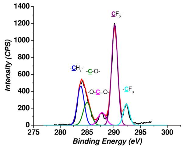
In Figure 2 are shown XPS survey spectra of PMMA, PMMA-O and PMMA-O-F surfaces. The X-ray photoelectron survey spectrum of the PMMA-O-F surface exhibited a strong F1s peak and small Si2s and Si2p peaks along with C1s and O1s peaks, confirming that HFTTCS reacted with the oxygen plasma-treated PMMA surface and generated a fluorination layer on PMMA. The high-resolution C1s spectrum of the PMMA-O-F substrate (Figure 3) showed characteristic C1s peaks due to -CF2- and –CF3 along with the C1s peaks associated with –CH2- , -C-O-, and -C(=O)-OR groups.
Figure 3.
High-resolution C1s X-ray photoelectron spectra of a perfluoro silane treated PMMA surface (PMMA-O-F). These spectra were recorded using a monochromatic Al Kα X-ray source at 150 W X-ray beam power with 40 eV pass energy. Curve fitting of the C1s peak (X2 = 0.71) gave rise to 5 peaks corresponding to a hydrocarbon (–CHx-) at 284.6 eV, carbon attached to an oxygen atom (C-O) and a carboxyl group (-O-C=O-) at 286.2 and 289.1 eV, respectively, and two peaks at 291.7 and 294.1 eV associated with –CF2- and -CF3 groups. The thickness of the PMMA film used was 250 μm.
Surface selectivity and the nature of the fluoro-silanization reaction on PMMA substrates
The surface concentration gradient of the HFTTCS layer was measured by angle-dependent XPS. In angle-dependent XPS measurements, the X-ray photoelectron spectra are recorded at two or more take-off angles by rotating the sample relative to the analyzer. The approximate sampling depth, d, at different take-off angles, θ, was determined using equation (1);41
| (1) |
where θ is the angle between the sample surface and the emitted electron path to the analyzer and λ is the inelastic mean free path (IMFP) of the electrons. Approximately 95% of the photoelectrons detected by the analyzer are emitted from the sampling depth determined by equation (1). Hence, the maximum sampling depth was obtained while recording the spectra at a take-off angle normal to the surface (θ = 90°). However, as the angle of analysis decreases, the sampling depth also decreases.
The O1s/C1s ratio of the PMMA-O surface obtained at two different take-off angles, 90° and 30°corresponding to a depth of analysis of 100 Å and 50 Å,42, 43 were 0.361 and 0.362, respectively. This indicated that oxygen plasma treatment modified the PMMA substrate more than 100 Å into the surface. The values for depth of analysis at different take-off angles were obtained using the reported value for the mean free path of the electrons of 33 Å in PMMA for Al Kα radiation.44 The F1s/C1s ratios obtained at 90° and 30° take-off angles for the PMMA-O-F surface were 1.347 and 1.364, respectively. The O1s/C1s ratios for the PMMA-O-F surface at 90° and 30° take-off angles were 0.1768 and 0.1225, respectively. This data indicated a decrease in oxygen-containing groups with a simultaneous marginal enhancement of the perfluoro groups within 50 Å of the surface. The X-ray photoelectron survey spectra also indicated that the amount of surface oxygen groups for the PMMA-O-F films was reduced considerably compared to the PMMA-O surface as expected for a carbon/fluorine layer on top of an underlying carbon/oxygen substrate. These results showed that the reaction of HFTTCS with the PMMA-O surface is limited to the outermost few nanometers of the PMMA surface.
In order to probe for any possible changes in the topography of the PMMA substrates during the modification protocol outlined in Scheme 1, SFM was employed to determine the surface topology. Surface topographical measurements are important for two reasons: 1) Determine if the silanization reaction protocol (Scheme 1) would impact the integrity of micron- and/or submicron-sized structures fabricated into the substrate via molding; and 2) water contact angle changes imposed by changes in the surface roughness, with higher surface roughness factors resulting in higher water contact angles for chemically similar surfaces.45 For example, it has been reported that gas plasma treatment of polymer surfaces may increase their roughness.30
In Figure S-4 of the Supporting Information are shown typical surface topographs of PMMA, PMMA-O and PMMA-O-F surfaces obtained by non-contact mode SFM.46 In comparison to the native (untreated) PMMA surface, which possessed a root-mean-square (RMS) surface roughness of 2.2 ±0.6 nm and a surface roughness factor (R) of 1.2, the PMMA-O surface exhibited a set of characteristic features that most likely resulted from PMMA etching during the oxygen plasma treatment giving rise to a slight increase in the RMS roughness (5.5 ±0.8 nm) and R = 1.8. The PMMA-O-F surface possessed a topography similar to that of the PMMA-O surface, but surface features appeared to be less defined and sharp resulting in an RMS roughness of 4.5 ±0.4 nm and R = 1.7.
Time dependent nature of the fluoro-silanization reaction
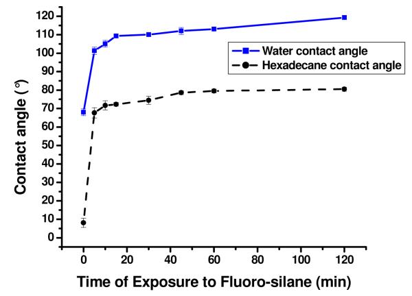
The progress of the fluorination reaction was initially followed by measuring the water contact angle of the PMMA-O surface upon reaction with HFTTCS at different time intervals, Figure 4. The water contact angle increased significantly during the first 20 min of the reaction and then began to level off toward a limiting value of 119 ±1° after 2 h of reaction with the fluoro-silane reagent. This value is similar to the water contact angle value reported for HFTTCS monolayers supported on silica/Si wafers.40, 47 Because the surface roughness of PMMA did not increase significantly during the fluorination process as outlined above (see Figure S-4), the increase in the water contact angles were primarily due to the introduction of fluorinated hydrocarbons to the PMMA surface and not roughness changes in the surface.
Figure 4.
Sessile-drop water (blue squares, solid line) and hexadecane (black circles, dashed line) contact angles on PMMA-O surfaces after their reaction with 1 × 10⁻³ M HFTTCS in FC-3283 for different time periods.
Contact angle measurements using hexadecane as a probe liquid were also carried out as a function of reaction time (see Figure 4) to evaluate the surface composition. Hexadecane contact angle (HDCA) measurements have been shown to be sensitive to the degree of fluorination.47 For example, the HDCA values reported by Weinstein et al. for a series of partially fluorinated alkanethiol monolayers supported on Au with different numbers of terminal C-F groups (CF3(CF2)n-1(CH)mSH, n+m = 16) were in the range of 74 to 83°.47 The maximum HDCA value for these partially fluorinated alkanethiol monolayers reported was 83° for the n = 8 case.47 The HDCA value reported for a CH3(CH2)15SH monolayer was 51°.47 Hence, HDCA values are sensitive to the hydrocarbon groups but a sufficiently thick and densely packed fluorocarbon layer can shield the underlying hydrocarbon layer. 47
HDCA values (Figure 4) showed that as the silane reaction time was increased, the amount of fluorinated surface groups increased as well. After 2 h of exposure to the fluorosilane reagent, the resulting PMMA-O-F surfaces possessed a HDCA value of 80 ±2°, indicating good coverage of the HFTTCS layer on the PMMA surface. The HDCA value increased from 8° for the PMMA-O surface (reaction time = 0 min) to 80° for the 2 h HFTTCS treated surface indicated that the fluorinated chains of the HFTTCS layer are sufficiently densely packed after a reaction time of 2 h. As a result, a reaction time of 2 h was selected for all subsequent studies.
We also monitored the time-dependency of the fluoro-silanization reaction via angle-resolved XPS and the results of which are summarized in Table 1. For a HFTTCS reaction time of 1 h, there was a significant difference between the F1s/C1s ratio at a 30° take-off angle (1.003) compared to that at 90° (0.816). Recalling that these take-off angles yield escape depths of approximately 50 Å and 100 Å, respectively, it is evident from the data shown in Table 1 that the surface density of the perfluoro chains was not uniform over the beam sampling area for a 1-h reaction time. However, for a 2-h reaction time, the difference between these ratios was marginal with F1s/C1s ratios being 1.364 (30°) and 1.347 (90°). Thus, for a 2-h reaction time, the resulting HFTTCS layer is much more dense and uniform.
Table 1.
The F1s/C1s ratio obtained at two different XPS take-off angles (ToA) for PMMA-O surfaces reacted with HFTTCS for 1 and 2 h.
| Sample | F1s/C1s ratio |
|
|---|---|---|
| ToA = 30° | ToA = 90° | |
| PMMA-O-F (1h) | 1.003 | 0.816 |
| PMMA-O-F (2h) | 1.364 | 1.347 |
Effect of HFTTCS concentration and plasma treatment time on HFTTCS monolayer formation
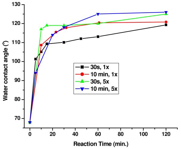
By measuring the water contact angles of the modified surface at different reaction times, we evaluated the effects of HFTTCS concentration on the fluoro-silanization reaction, Figure 5. In general, for all conditions explored the initial rate of the fluoro-silane layer formation was virtually the same with only subtle differences occurring at later reaction times. In particular for [HFTTCS] = 1 × 10⁻³ M, the maximum WCA values obtained were 119 and 121° for a 30 s and 10 min oxygen plasma treatment time, respectively, and for [HFTTCS] = 5 × 10⁻³ M, the maximum WCA values obtained were 125 and 126° for the 30s and 10 min plasma treatment time, respectively. Thus, increasing the concentration of HFTTCS marginally increased the WCA value and hence the extent of fluorination. There was no observable trend in the rate of HFTTCS monolayer formation with oxygen plasma time (see Figure 5).
Figure 5.
Water contact angles of PMMA surfaces plasma treated for 30 s and 10 min and then exposed to 1 × 10⁻³ M (1×) or 5 × 10⁻³ M (5×) heptadecafluoro-1,1,2,2–tetrahydrodecyl trichlorosilane in FC-3283 for different time intervals (reaction time).
Fluorination of PMMA-based DMFDs
We utilized the reaction procedure (see Scheme 1) to fluorinate microchannel surfaces embossed into a PMMA substrate with a design outlined in Figure 1. Embossed PMMA DMFDs and the PMMA cover plate were treated with an oxygen plasma for 30 s followed by thermal fusion bonding of the cover plate onto the DMFD to enclose the fluidic network. This was followed by flowing a 1 × 10⁻³ M solution of HFTTCS in FC-3283 through the channels for 2 h at a volume flow rate of 2 μL min−1 followed by rinsing the fluidic network with FC-3283 at a flow rate of 10 μL min−1 for 30 min. Liquid-liquid segmented flow tests were conducted on this device with FC-3283 as the carrier fluid and de-ionized water as the dispersed fluid. No significant improvements in the segmented flow stability were observed compared to a device in which the surface was not modified. Both devices showed significant wetting of the surface by water droplets within 1 h of operation. Therefore, it was concluded that the fluoro-silanization reaction did not lead to complete coverage of the PMMA surface by the fluorinated hydrocarbon. The probable reason for the lack of improvement in the performance of the modified PMMA DMFD is due to the movement of hydrophilic hydroxyl groups toward the bulk from the surface during thermal fusion bonding and hence not available for fluorination reaction. It is known that polymer surfaces containing hydrophilic groups that upon heating in air results in the movement of these hydrophilic groups toward the bulk of the polymer.48 The rate of this process, also known as hydrophobic recovery, increases significantly above Tg. This phenomenon is especially prevalent for thermoplastics above their Tg due to the mobility of the polymer chains.48
The water contact angle of a PMMA film surface treated with 30 s oxygen plasma (PMMA-O), heated to 104 °C for 20 min (PMMA-O-Th) and then fluorinated for 2 h (PMMA-O-Th-F) was 73 ± 2°. This showed insignificant fluorination of the surface and explained the lack of improvement in the performance of the fluorinated PMMA DMFD following thermal assembly. This was further confirmed by XPS. The F1s/C1s ratio of the PMMA-O-Th-F surface was 0.037, which was much less than the non-thermally-treated PMMA substrate (1.347).
To overcome this problem, the PMMA DMFD was first thermal fusion bonded with the PMMA cover plate and the enclosed PMMA DMFD was subsequently treated with oxygen plasma for 10 min and finally, the fluorination reaction was carried out on the assembled device. To evaluate the effectiveness of the oxygen plasma treatment for the modification of the PMMA surface inside the assembled chip, a hydroxyl group reactive dye, 5-(4,6-dichlorotriazinyl)aminofluorescein, DTAF was used.49, 50 We found that the enclosed PMMA cover plate after DTAF labeling and removed from the assembled device showed a rather uniform fluorescence signal, whereas the control cover plate surface showed no fluorescence signal. These data (Figure S-4, Supporting Information) indicated that the oxygen plasma treatment effectively modified the PMMA surface inside the enclosed fluidic device.
Effect of time delay between plasma treatment and the fluoro-silanization reaction
We also evaluated whether the PMMA-O surface would undergo hydrophobic recovery when remaining at room temperature for extended periods of time. Planar PMMA substrates were treated with an oxygen plasma and then exposed to HFTTCS immediately, after 1 h and then, after 2 h with the substrates stored at room temperature in all cases. The water and hexadecane contact angles were investigated with the results summarized in Table 2. We observed no significant differences in the contact angles even after a 2 h delay between the plasma treatment and the subsequent HFTTCS reaction indicating that there was no observable hydrophobic recovery during the time span investigated.
Table 2.
Effects of time delay between oxygen plasma treatment and the fluoro-silanization reaction on the extent of fluorination of the PMMA surface measured by water and hexadecane contact angle measurements.
| Time delay between oxygen plasma treatment and fluoro-silane treatment |
Water contact angle |
Hexadecane contact angle |
|---|---|---|
| No delay | 121 ± 4° | 82 ± 2° |
| 1 h | 121 ± 1° | 81 ± 1° |
| 2 h | 120 ± 2° | 82 ± 1° |
Evaluation of PMMA microfluidic devices with liquid-liquid segmented flows
To construct devices to be used for liquid-liquid segmented flow experiments, the following protocol was used. First, the PMMA cover plate was thermally bonded to a molded PMMA substrate containing the fluidic network. Then, oxygen plasma treatment was carried out on the assembled chip that possessed reservoirs open to the atmosphere (see Figure 1). Because access of oxygen plasma to the PMMA channel surfaces was limited by diffusion through the channel network, we used an oxygen plasma treatment time of 10 min (see Figure S-4). This step was followed by a 2 h reaction with 5 × 10⁻³ M HFTTCS/FC-3283 solution flowed at 2 μL min−1 through the chip followed by rinsing the channel with FC-3283 at 10 μL min−1 for 30 min.
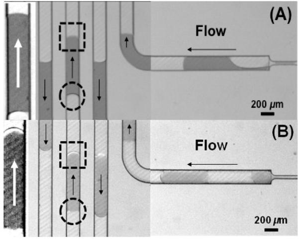
To investigate the effects of fluoro-silanization on the wetting properties of the channel walls of PMMA microfluidic devices during segmented flow operation, the advancing (heads) and receding (tails) menisci of aqueous droplets flowing in both unmodified and fluorinated microchannels were compared using the same operating conditions, Figure 6. Surfactant was not used in these experiments in order to see the effects of surface fluorination on the formation of distinct menisci shapes. The advancing water droplet menisci were more rounded in the fluorinated PMMA microchannels relative to their unmodified counterparts, as noted when comparing Figures 6A and 6B. These results were indication of a lack of microchannel wall wetting by the aqueous droplets for the fluorinated PMMA surface. For the pristine PMMA microchannel walls, they appeared to be wetted by the aqueous droplets in the fluorocarbon-based carrier fluid because the apparent dynamic wetting angle of the receding meniscus favored a higher meniscus curvature of opposite sign relative to the advancing one. This capillary effect at the corners of the microchannels makes the meniscus curvature more pronounced. In the case of the modified (fluorinated) PMMA microchannel walls, the receding meniscus appeared flat, consistent with an increased wetting angle with respect to the water droplet and therefore, a reduced capillary effect at the corners.
Figure 6.
Different advancing (dotted square) and receding (dotted circle) menisci of segmented aqueous droplets flowing in (A) pristine and (B) fluorinated PMMA microchannels. FC-3283 was used as the carrier fluid using a volume flow rate of 10 μL min−1 and the dispersed fluid at 2 μL min−1. Arrows denote the flow direction. Magnified and enhanced images are shown on the far left of the figures. Section B and part of section C of the microfluidic device shown in Figure 1 are shown here.
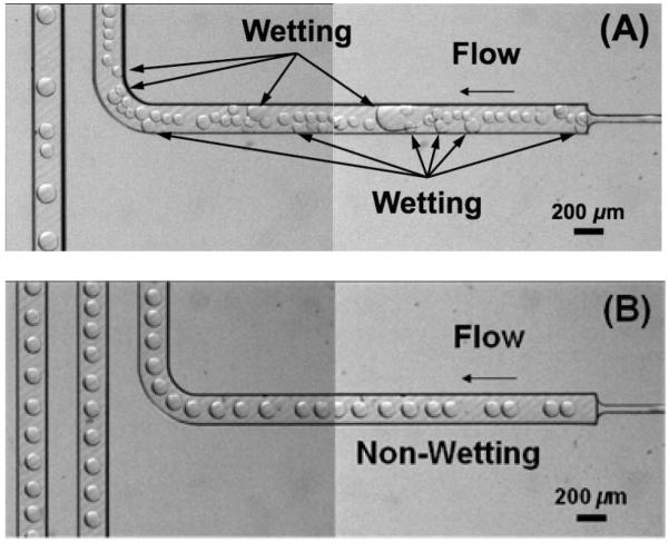
Another qualitative confirmation of the effect of fluorination of the polymer microchannel walls was obtained through an experiment that promoted contact of the aqueous dispersed fluid with the microchannel wall under static conditions (zero capillary number). This was achieved through the following experimental protocol: 30 min of continuous injection of the dispersed fluid (2 μL/min) and the carrier fluid (10 μL/min) without surfactant, halt injection of the dispersed and carrier fluids and leave the chip under stationary conditions for 12 h, restart injection at the same flow rates switching to a carrier fluid with surfactant (FC 3283 + PFO 10% v/v). As shown in Figure 7A, the aqueous droplet wetted the un-treated micro-channel surfaces and remained even after the addition of surfactant. This resulted in highly irregular droplet flow throughout the test channel. To the contrary, the aqueous droplets did not wet the fluorinated microchannel walls over the entire chip fluidic network, Figure 7B, and as a result, highly regular droplet flows were achieved and maintained throughout the fluorinated test microchannel.
Figure 7.
Wetting and non-wetting of channel surfaces by aqueous droplets on the surfaces of (A) pristine and (B) fluorinated PMMA microchannels. Images were taken after the following working protocol: 30 min of continuous injection of the dispersed fluid (2 μL min−1) and the carrier fluid (10 μL min−1) without surfactant, halting injection of the dispersed and carrier fluids and leaving the chip under stationary conditions for 12 h, restarting injection at the same flow rates and switching to a carrier fluid with surfactant (FC 3283 + PFO 10% v/v).
We surmised that the modification protocol outlined in Scheme 1 should be applicable to other polymer surfaces as long as they possessed surface hydroxyl groups resulting from oxygen plasma treatment. In order to evaluate this, we applied the reaction outlined in Scheme 1 to other polymers, in particular PC and COC. The results shown in the Supporting Information demonstrated that the surfaces of PC and COC could be fluorinated using the protocol shown in Scheme 1. The PC and COC surfaces, upon fluorination, exhibited a water contact angle of 115 ±2° and 116 ±2°, respectively, and the hexadecane contact angle values were 77 ±1° and 76 ±2°, respectively. These values were nearly the same as those found for the fluoro-silanized PMMA indicating that the layers formed on PC and COC were similar in structure to that on PMMA. Angle-resolved XPS analyses indicated that fluoro-silanization of oxygenated PC and COC surfaces occurred similarly to that found for PMMA (see the XPS survey spectra for PC and COC in Figures S-1 and S-2, respectively). In addition, the fluorination of PC and COC surfaces occurred with more surface selectivity compared to the fluorination of the PMMA surface. We also found that using this reaction scheme, the surface of glass and PDMS could also be fluorinated with high surface selectivity (data not shown). A summary of water contact angle data for each step of the fluorination reaction for PMMA, PC and COC are summarized in Table S-1 found in the Supporting Information. Table S-2 contains a summary of the angle-resolved XPS data for the pristine, oxygen plasma-treated and fluorinated surfaces for COC, PC and PMMA.
Conclusions
We have developed a simple procedure for the highly efficient fluorination of different polymer substrates employed for the fabrication of microfluidic devices used to generate segmented flows. In addition, the fluorination procedure reported herein is general enough to be used with a variety of hydrophobic carrier fluids. In this procedure, polymer films were oxidized using an oxygen plasma, which introduced hydroxyl and other oxygen-containing hydrophilic groups such as carbonyl, carboxyl and peroxide moieties, onto the polymer film. The oxidized polymer surface could then be reacted with a solution of heptadecafluoro-1,1,2,2–tetrahydrodecyl trichlorosilane in a perfluoro liquid, FC-3283. Water contact angle and XPS data showed that this reaction was complete within 2 h. The reaction protocol was then modified for producing DMFDs to accommodate the surface dynamics associated with polymer microfluidic devices using thermal fusion bonding, which required heating the polymer above its Tg, to enclose the fluidic network. Instead of oxygen plasma treatment prior to thermal fusion bonding, the substrate containing the molded fluidic network and cover plate were bonded followed by oxygen plasma treating the assembled device. In this fashion, the functional groups introduced by the oxygen plasma remained on the surface and lead to the formation of a monolayer of perfluoro silane on the fluidic channels’ surface. The modification protocol was applied to a PMMA DMFD and resulted in the generation of stable liquid-liquid segmented flows compared to PMMA devices not fluorinated. The fluorination protocol adopted herein was also found to yield similar results for other thermoplastics, such as PC and COC.
Supplementary Material
Acknowledgements
The authors acknowledge support of this work through the National Institutes of Health (EB-006639), the National Science Foundation (EPS-0346411 and EPS-0701491) and the Louisiana Board of Regents. The authors also acknowledge partial financial support of this work through the World Class University (WCU) program in Korea.
Footnotes
Supporting information: Water contact angle data for PC, PC-O, PC-O-F, COC, COC-O and COC-O-F surfaces. X-ray photoelectron spectra of PC, PC-O, PC-O-F, COC, COC-O and COC-O-F surfaces, as well as angle-resolved XPS data for PC, PC-O, PC-O-F, COC, COC-O and COC-O-F surfaces. Fluorescent and bright field images of PMMA cover plates removed from the enclosed DMFD after 10 min oxygen plasma treatment followed by DTAF labeling along with the control unmodified PMMA cover plate.
References
- 1.Teh S-Y, Lin R, Hung L-H, Lee AP. Lab on a Chip. 2008;8(2):198–220. doi: 10.1039/b715524g. [DOI] [PubMed] [Google Scholar]
- 2.Belder D. Angewandte Chemie, International Edition. 2005;44(23):3521–3522. doi: 10.1002/anie.200500620. [DOI] [PubMed] [Google Scholar]
- 3.Berthier J. Microdrops and Digital Microfluidics. William Andrew Inc.; Norwich, NY: 2008. [Google Scholar]
- 4.Joanicot M, Ajdari A. Science (Washington, DC, United States) 2005;309(5736):887–888. doi: 10.1126/science.1112615. [DOI] [PubMed] [Google Scholar]
- 5.Kobayashi I, Uemura K, Nakajima M. Colloids and Surfaces, A Physicochemical and Engineering Aspects. 2007;296(1-3):285–289. [Google Scholar]
- 6.Bringer MR, Gerdts CJ, Song H, Tice JD, Ismagilov RF. Philosophical Transactions of the Royal Society of London, Series A Mathematical, Physical and Engineering Sciences. 2004;362(1818):1087–1104. doi: 10.1098/rsta.2003.1364. [DOI] [PMC free article] [PubMed] [Google Scholar]
- 7.Burns JR, Ramshaw C. Lab Chip. 2001;1(1):10–15. doi: 10.1039/b102818a. [DOI] [PubMed] [Google Scholar]
- 8.Song H, Ismagilov RF. Journal of the American Chemical Society. 2003;125(47):14613–14619. doi: 10.1021/ja0354566. [DOI] [PMC free article] [PubMed] [Google Scholar]
- 9.Guenther A, Khan SA, Thalmann M, Trachsel F, Jensen KF. Lab Chip. 2004;4(4):278–286. doi: 10.1039/b403982c. [DOI] [PubMed] [Google Scholar]
- 10.Curcio M, Roeraade J. Analytical Chemistry. 2003;75(1):1–7. doi: 10.1021/ac0204146. [DOI] [PubMed] [Google Scholar]
- 11.Schaerli Y, Wootton RC, Robinson T, Stein V, Dunsby C, Neil MAA, French PMW, deMello AJ, Abell C, Hollfelder F. Analytical Chemistry. 2009;81(1):302–306. doi: 10.1021/ac802038c. [DOI] [PubMed] [Google Scholar]
- 12.Kline TR, Runyon MK, Pothiawala M, Ismagilov RF. Anal. Chem. (Washington, DC, U. S.) 2008;80(16):6190–6197. doi: 10.1021/ac800485q. [DOI] [PMC free article] [PubMed] [Google Scholar]
- 13.Shepherd RF, Conrad JC, Rhodes SK, Link DR, Marquez M, Weitz DA, Lewis JA. Langmuir. 2006;22(21):8618–8622. doi: 10.1021/la060759+. [DOI] [PubMed] [Google Scholar]
- 14.Nie Z, Li W, Seo M, Xu S, Kumacheva E. Journal of the American Chemical Society. 2006;128(29):9408–9412. doi: 10.1021/ja060882n. [DOI] [PubMed] [Google Scholar]
- 15.Hwang DK, Dendukuri D, Doyle PS. Lab on a Chip. 2008;8(10):1640–1647. doi: 10.1039/b805176c. [DOI] [PubMed] [Google Scholar]
- 16.Li L, Mustafi D, Fu Q, Tereshko V, Chen Delai L, Tice Joshua D, Ismagilov Rustem F. Proc. Natl. Acad. Sci. U. S. A. 2006;103(51):19243–8. doi: 10.1073/pnas.0607502103. [DOI] [PMC free article] [PubMed] [Google Scholar]
- 17.Yamada M, Doi S, Maenaka H, Yasuda M, Seki M. Journal of Colloid and Interface Science. 2008;321(2):401–407. doi: 10.1016/j.jcis.2008.01.036. [DOI] [PubMed] [Google Scholar]
- 18.Adamson DN, Mustafi D, Zhang JXJ, Zheng B, Ismagilov RF. Lab Chip. 2006;6(9):1178–1186. doi: 10.1039/b604993a. [DOI] [PMC free article] [PubMed] [Google Scholar]
- 19.Chen DL, Ismagilov RF. Current Opinion in Chemical Biology. 2006;10(3):226–231. doi: 10.1016/j.cbpa.2006.04.004. [DOI] [PMC free article] [PubMed] [Google Scholar]
- 20.McDonald JC, Duffy DC, Anderson JR, Chiu DT, Wu H, Schueller OJA, Whitesides GM. Electrophoresis. 2000;21(1):27–40. doi: 10.1002/(SICI)1522-2683(20000101)21:1<27::AID-ELPS27>3.0.CO;2-C. [DOI] [PubMed] [Google Scholar]
- 21.McDonald JC, Whitesides GM. Accounts of Chemical Research. 2002;35(7):491–499. doi: 10.1021/ar010110q. [DOI] [PubMed] [Google Scholar]
- 22.Diaz-Quijada GA, Peytavi R, Nantel A, Roy E, Bergeron MG, Dumoulin MM, Veres T. Lab Chip. 2007;7(7):856–862. doi: 10.1039/b700322f. [DOI] [PubMed] [Google Scholar]
- 23.Becker H, Gartner C. Analytical and Bioanalytical Chemistry. 2008;390:89–111. doi: 10.1007/s00216-007-1692-2. [DOI] [PubMed] [Google Scholar]
- 24.Becker H, Locascio LE. Talanta. 2002;56(2):267–287. doi: 10.1016/s0039-9140(01)00594-x. [DOI] [PubMed] [Google Scholar]
- 25.Roach LS, Song H, Ismagilov RF. Analytical Chemistry. 2005;77(3):785–796. doi: 10.1021/ac049061w. [DOI] [PMC free article] [PubMed] [Google Scholar]
- 26.Hayes LJ, Dixon DD. Text. Res. J. 1977;47(4):277–82. [Google Scholar]
- 27.Wang J-H, Chen J-J, Timmons RB. Chem. Mater. 1996;8(9):2212–2214. [Google Scholar]
- 28.Schmidt DL, Coburn CE, DeKoven BM, Potter GE, Meyers GF, Fischer DA. Nature (London) 1994;368(6466):39–41. [Google Scholar]
- 29.Ferguson GS, Chaudhury MK, Biebuyck HA, Whitesides GM. Macromolecules. 1993;26(22):5870–5. [Google Scholar]
- 30.Ward LJ, Badyal JPS, Goodwin AJ, Merlin PJ. Polymer. 2005;46(12):3986–3991. [Google Scholar]
- 31.Anderson A, Ashurst WR. Langmuir. 2009;25(19):11541–11548. doi: 10.1021/la9014543. [DOI] [PubMed] [Google Scholar]
- 32.Balamurugan S, Obubuafo A, Soper SA, McCarley RL, Spivak DA. Langmuir. 2006;22(14):6446–6453. doi: 10.1021/la060222w. [DOI] [PubMed] [Google Scholar]
- 33.Ron H, Matlis S, Rubinstein I. Langmuir. 1998;14(5):1116–1121. [Google Scholar]
- 34.McCrackin FL, Passaglia E, Stromberg RR, Steinberg HL. Journal of Research of the National Bureau of Standards, Section A Physics and Chemistry. 1963;A67(4):363–77. doi: 10.6028/jres.067A.040. [DOI] [PMC free article] [PubMed] [Google Scholar]
- 35.Prime KL, Whitesides GM. Journal of the American Chemical Society. 1993;115(23):10714–21. [Google Scholar]
- 36.Adams AA, Okagbare PI, Feng J, Hupert ML, Patterson D, Gottert J, McCarley RL, Nikitopoulos D, Murphy MC, Soper SA. Journal of the American Chemical Society. 2008;130(27):8633–8641. doi: 10.1021/ja8015022. [DOI] [PMC free article] [PubMed] [Google Scholar]
- 37.Hupert ML, Guy WJ, Llopis SD, Shadpour H, Rani S, Nikitopoulos DE, Soper SA. Microfluidics and Nanofluidics. 2007;3(1):1–11. [Google Scholar]
- 38.Henry AC, Tutt TJ, Galloway M, Davidson YY, McWhorter CS, Soper SA, McCarley RL. Analytical Chemistry. 2000;72(21):5331–5337. doi: 10.1021/ac000685l. [DOI] [PubMed] [Google Scholar]
- 39.Wei S, Vaidya B, Patel AB, Soper SA, McCarley RL. Journal of Physical Chemistry B. 2005;109(35):16988–16996. doi: 10.1021/jp051550s. [DOI] [PubMed] [Google Scholar]
- 40.Schweikl H, Mueller R, Englert C, Hiller K-A, Kujat R, Nerlich M, Schmalz G. Journal of Materials Science Materials in Medicine. 2007;18(10):1895–1905. doi: 10.1007/s10856-007-3092-8. [DOI] [PubMed] [Google Scholar]
- 41.Desimoni EZ. Spectroscopies for Surface Characterization. VCH; Weinheim: 1993. pp. 1–45. [Google Scholar]
- 42.Bhatia QS, Pan DH, Koberstein JT. Macromolecules. 1988;21(7):2166–75. [Google Scholar]
- 43.Tyler BJ, Castner DG, Ratner BD. Surface and Interface Analysis. 1989;14(8):443–50. [Google Scholar]
- 44.Roberts RF, Allara DL, Pryde CA, Buchanan DNE, Hobbins ND. Surface and Interface Analysis. 1980;2(1):5–10. [Google Scholar]
- 45.Yeh K-Y, Chen L-J, Chang J-Y. Langmuir. 2008;24(1):245–251. doi: 10.1021/la7020337. [DOI] [PubMed] [Google Scholar]
- 46.Kim NL,W, Balamurugan S, Murphy MC, Soper SA. Micro-Scale Liqui-Liquid Segmented Flows for Enzyme Activity Monitoring. ICMF; Tampa, FL: 2010. Nikitopoulos. Tampa, FL, 2010. [Google Scholar]
- 47.Weinstein RD, Moriarty J, Cushnie E, Colorado R, Jr., Lee TR, Patel M, Alesi WR, Jennings GK. J. Phys. Chem. B. 2003;107(42):11626–11632. [Google Scholar]
- 48.Morra M, Occhiello E, Garbassi F. Angewandte Makromolekulare Chemie. 1991;189:125–36. [Google Scholar]
- 49.Dementev N, Feng X, Borguet E. Langmuir. 2009;25(13):7573–7577. doi: 10.1021/la803947q. [DOI] [PubMed] [Google Scholar]
- 50.Ahmed F, Alexandridis P, Neelamegham S. Langmuir. 2001;17(2):537–546. [Google Scholar]
Associated Data
This section collects any data citations, data availability statements, or supplementary materials included in this article.


