Abstract
Experimental studies play an important role in establishing the safety and efficacy of cochlear implants and they continue to provide insight into a new generation of electrode arrays and stimulation strategies. One drawback has been the limited depth of insertion of an electrode array in experimental animals. We compared the insertion depth and trauma associated with the insertion of Cochlear Ltd’s Hybrid-L (HL) array with a standard 8 ring array in cat cochleae. Both arrays were inserted into cadaver cochleae and an X-ray recorded their anatomical location. The implanted cochlea was serially sectioned and photographed at 300µm intervals for evidence of electrode insertion trauma.
Subsequently two cats were chronically implanted with HL arrays and electrically-evoked potentials recorded over a three month period. Mean insertion depth for the HL arrays was 334.8° (SD = 21°; n=4) versus 175.5°(SD = 6°; n=2) for the standard array. This relates to ~10.5 mm and 6 mm respectively. A similar insertion depth was measured in a chronically implanted animal with a HL array. Histology from each cadaver cochleae showed that the electrode array was always located in the scala tympani; there was no evidence of electrode insertion trauma to the basilar membrane, the osseous spiral lamina or the spiral ligament. Finally, evoked potential data from the chronically implanted animals exhibited significantly lower thresholds compared with animals implanted with a standard 8 ring array, with electrical thresholds remaining stable over a three month observation period. Cochlear Ltd’s HL electrode array can be safely inserted ~50% of the length of the cat scala tympani, placing the tip of the array close to the 4 kHz place. This insertion depth is considerably greater than is routinely achieved using a standard 8-ring electrode array (~12 kHz place). The HL array evokes low thresholds that remain stable over three months of implantation. This electrode array has potential application in a broad area of cochlear implant related research.
Keywords: Cochlear implant, electrode array, electrical stimulation, neural prostheses, deafness
1. Introduction
Cochlear implants have had a major impact on the clinical treatment of the severe-to-profoundly deaf. Experimental studies performed in appropriate animal models of sensorineural hearing loss have played an important role in establishing the safety and efficacy of these devices (review: Shepherd, and McCreery 2006). Animal studies continue to provide insight into a new generation of electrode arrays, stimulation strategies and biomaterials, leading to improved clinical outcomes.
A major benefit of these experimental studies is the ability to perform well controlled experiments while obtaining electrophysiological, histological and behavioral data from the one animal. One restriction associated with this work has been the relatively limited depth of insertion of an electrode array in experimental animals compared to the human. The most common animal models used in acute and chronic cochlear implant studies include the rat, guinea pig and cat. While it is possible to design electrode arrays with a cross-sectional surface area small enough to be inserted atraumatically into the basal turn of these species (Table 1), it has been difficult to develop electrode arrays that can be safely inserted beyond the lower basal turn because of the highly tapered and tightly spiraling nature of the scala tympani (Salt, 2010).
Table 1.
Comparative cochlear anatomy and published electrode insertion distances
| Species | Length of scala tympani (mm) |
Cross sectional area of scala tympani in basal turn (mm2) |
Volume of scala tympani (µl) |
Published electrode insertion depths (mm) |
|---|---|---|---|---|
| Rat | 7.2a | 0.1 a | 1.0 a | 2–3d |
| Guinea pig | 16.2 a | 0.4 a | 4.8 a | 2–4.5e |
| Cat | 22c | 2.0 b | N/A | 4–8f |
| Human | 28.5 a | 2.2 a; 2.0 b | 29.2 a | <25g |
As a result, current electrode arrays for animal use typically only extend over the basal most 30% of the cochlea (Table 1). Because cochlear implants encode the pitch by electrode place, i.e. activation of different electrode contacts along the electrode array, the limited number of electrodes and depth of insertion in animal models compared to the human has resulted in a limitation in the use of these animal models to study spatial properties of cochlear implant stimulation. The development of electrode arrays that can be safely inserted significantly further within the cochlea will have a positive impact on this research. Such electrode arrays would have important application in: i) plasticity studies that examine the ability of electrically induced neural activity to drive plastic change within the central auditory pathway; ii) the study of simultaneous sites of electrical stimulation to produce more focused patterns of neural excitation; iii) more accurate models of bilateral cochlear implantation as the electrodes will access more apical regions of the cochlea important for sound localization; iv) more accurate models of electrode insertion trauma as the electrode array is inserted beyond the lower basal turn; and v) more accurate models of electric-acoustic hearing.
There have been a number of reports describing improved electrode arrays for experimental studies including attempts to develop arrays designed for greater insertion depths (Rebscher et al. 2007). The present study contributes to this theme by evaluating a new electrode array for its suitability for deep but atraumatic insertion within the cat scala tympani. Importantly, this array is manufactured from materials identical to those used clinically and is therefore suitable for chronic application.
2. Methods & Materials
2.1 Tissue preparation
Six adult cat cadaver cochleae were used to evaluate the depth of insertion and trauma in vitro. Each cochlea was stored in neutral buffered formalin prior to the electrode insertion trial. Just prior to the trial the auditory bulla was opened to expose the round window of the cochlea.
2.2 Electrode arrays
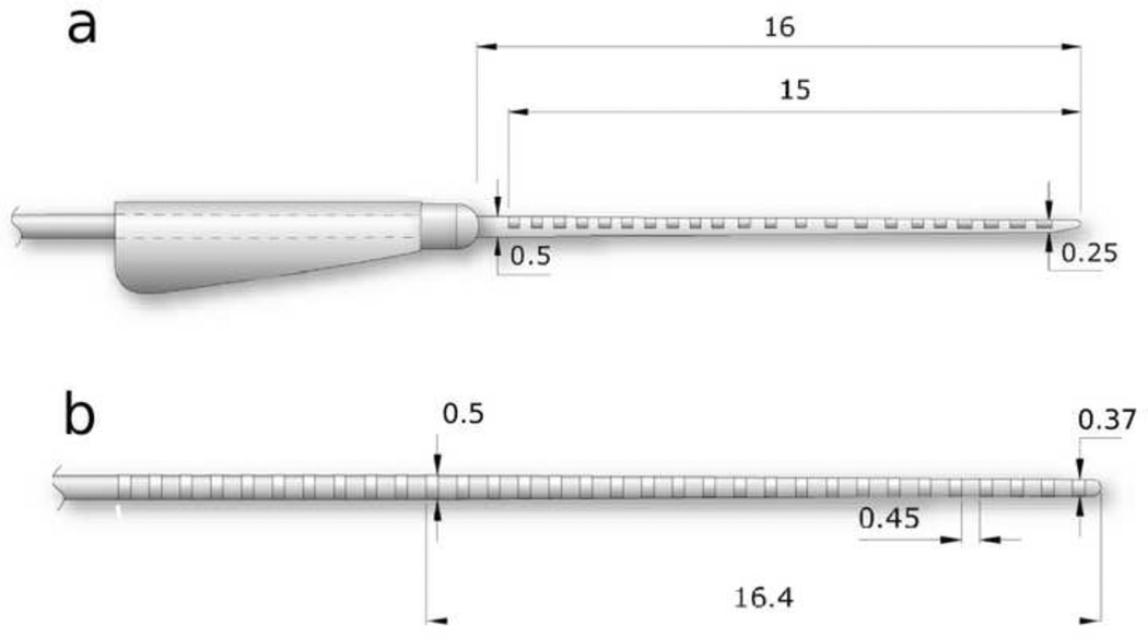
Two types of electrode arrays were used in the present study (Fig. 1). We compared the insertion depth and extent of trauma associated with the insertion of Cochlear Ltd’s commercially available Hybrid-L24 (HL24) electrode array with a standard 8 ring electrode array we have used previously in chronic animal studies (Fallon et al. 2009a; Xu et al. 1997). The HL24 array is a straight lateral wall electrode array with a “soft-tip” design that improves its ability to be inserted around the spiral cochlea atraumatically (Briggs et al. 2006). It consists of 22 half-band platinum (Pt) electrodes on a silicone carrier. The diameter of the tip of the array is 0.25 mm increasing to 0.5 mm 15 mm from the tip (Fig. 1a; Briggs et al. 2006). Following initial trials of the HL24, two modified electrode arrays were developed (HL16 & HL14) consisting of 16 and 14 Pt electrodes respectively, having the electrodes distributed along the silicone carrier over a total length of 11.5 (HL16) or 10.5 mm (HL14) from the most basal electrode to the distal tip of the array. These arrays were identical to the HL24 apart from the removal of the basal 6 (HL16) or 8 (HL14) electrodes and appropriate adjustment of the remainder of the array assembly. Cochlear Ltd is about to introduce the HL14 electrode array as part of their standard catalogue of animal electrodes for research purposes and they will therefore be commercially available to the research community. The standard electrode array, which is commercially available from Cochlear Ltd for research purposes, consisted of 8 Pt ring electrodes on a silicone carrier. The tip diameter of the array was 0.37 mm, increasing to 0.5 mm at the eighth electrode which was located 6 mm from the tip of the array.
Figure 1.
Schematic diagrams of the two electrode arrays used in the present study. (a) Hybrid–L24 array consist of 16 half-band Pt electrodes on a silicone carrier. The electrodes were distributed over 11.5 mm length of the array proximal to the tip (the figure illustrates an array for human use containing 22 Pt electrodes). The diameter of the tip of the array was 0.25 mm increasing to 0.5 mm 15 mm from the tip. (b) Standard array consisted of eight Pt band electrodes on a silicone carrier. The electrodes were distributed over a 6 mm length of the array proximal to the tip (the figure illustrates an array for human use containing 32 Pt bands). The diameter of the tip of the array was 0.37 mm increasing to 0.5 mm 16.4 mm from the tip. All dimensions are in mm.
2.3 Electrode Insertion
Each temporal bone was prepared so that the view of the round window of each cochlea simulated the view observed surgically (Xu et al. 1997). The insertion of the electrode array was performed by two surgeons with considerable experience performing cochlear implantation surgery in this species. Using the assistance of a Zeiss Operating Microscope, the round window membrane was incised with a 25 G needle and the array gently inserted to the point of first resistance. Each cochlea was subject to a single insertion.
2.4 Microfocus X-ray and Fluoroscopy imaging
A Micro-focus X-ray imaging system (Xu and Cowan 2005) was used to image the electrode arrays in the present study. The system included a small aperture micro-focus X-ray source (<10 µm), an appropriate ratio of object-image distance to source-object distance, and a digital camera optically coupled to a high resolution X-ray image intensifier. The edge-enhanced phase-contrast and inherent image magnification offered by this system have advantages in showing the details of inner ear anatomy and the location of the electrode array, producing a magnified image with high resolution (Xu et al. 2001).
The fluoroscopic image of the electrode array insertions were observed and recorded in real time during the insertion of each electrode array (Xu et al. 2009). Still micro-focus radiographs, adapted from Cochlear View for human temporal bone studies (Xu et al. 2000), were taken at the completion of each insertion to identify the electrode position and to estimate insertion depth.
2.5 Histology
After insertion of the electrode array, the lead was secured by application of histoacryl® glue at the level of the facial recess and the stapes footplate was removed. The specimens were dehydrated in ethanol using serial concentrations progressing from 70% to 100% and immersed in degassed epoxy resin. Vacuum was applied so that the epoxy mixture infiltrated the cochleae completely. After embedding, the specimens were x-rayed to assess the correct plane for sectioning. Following appropriate orientation the blocks were re-embedded so that the modiolus of the cochlea was oriented parallel to the plane of sectioning and perpendicular to the electrode array. The cochleae were then serially sectioned using a grinding technique to a depth of 300 µm. At every 300 µm the surface was polished, stained with toluidine blue and photographed under a light microscope (Briggs et al. 2006; Tykocinski et al. 2000). These serial digital images were examined for evidence of electrode insertion trauma. Particular attention was given to examining the status of the basilar membrane, osseous spiral lamina and the spiral ligament lining on the outer wall of the scala tympani.
2.6 Depth of electrode insertion
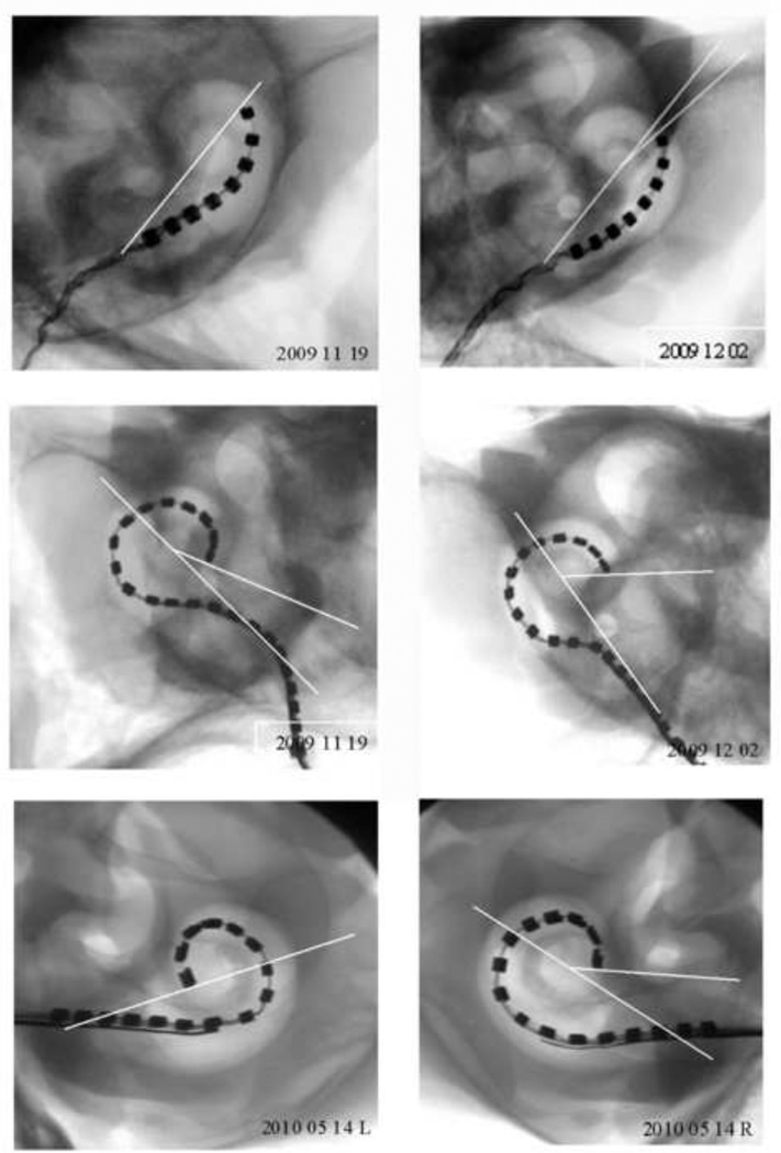
To estimate the insertion depth of each electrode array the orientation of the X-ray beam was directed parallel to the central axis of cochlea to enable the centre point of the cochlear spiral to be identified. The insertion depth (in degrees) was measured to the tip of each array by drawing a 180° reference line from the middle of the round window to the centre point of the cochlear spiral then creating a second angle from the centre point to the tip of the array (see Fig. 3).
Figure 3.
Micro-focus radiographs from all six cochleae used in this study (two standard, two Hybrid-L24 and two Hybrid-L16 electrode arrays). The insertion depth (in degrees) were measured to the tip of each array by drawing a 180° reference line from the middle of the round window to the centre point of the cochlear spiral then creating a second angle from the centre point to the tip of the array. Scale bar = 5 mm.
2.7 Chronic implantation of HL electrode arrays
Following the in vitro results, two young adult cats were unilaterally implanted with HL14 electrode arrays. The implantation technique followed the in vitro procedures described above with the addition of using sterile surgical procedures. Anesthesia was maintained throughout surgery via a closed circuit anesthetic machine (halothane/oxygen). The detailed surgical procedure has been described previously (Xu et al. 1997). Each electrode array was connected to a leadwire assembly which allowed the electrodes to be stimulated via a cochlear implant placed in a back pack worn by the animal (Fallon et al. 2009a). The position of the array in one animal was imaged using the micro-focus technique described above (see 2.4). The quality of the live X-ray image is slightly lower than the images obtained from the cadaver cochleae due to movement artifact associated with the animal’s breathing.
Electrophysiological data in the form of electrically-evoked auditory brainstem responses (EABRs) and Neural Response Telemetry (NRT) were periodically recorded from both animals over a 3 month implantation period. EABRs were recorded using techniques described previously (Fallon et al. 2009a) while NRTs were obtained using the standard clinical settings in Custom Sound EP (Cochlear Ltd). Threshold for each electrode was correlated with its position along the array and thresholds were compared with an age matched cohort of animals chronically implanted with the standard 8 ring electrode array (Fallon et al. 2009a). The chronic study was conducted under NHMRC Guidelines for Animal Experimentation and approved by the Animal Research Ethics Committee, Royal Victorian Eye and Ear Hospital, Melbourne, Australia (#09_187AB).
3. Results
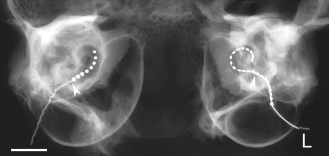
Figure 2 is a micro-focus radiograph of a standard 8 ring electrode array (right cochlea) and a HL24 (left cochlea) illustrating the typical insertion profiles obtained with each array in the present study. Both arrays were inserted via the round window. The depth of insertion of the standard array saw all 8 electrodes located within the scala tympani with the tip of the most apical electrode positioned approximately 6 mm from the round window. This insertion profile is similar to our previous experience using this array in cats (Coco et al. 2007; Fallon et al. 2009a; Xu et al. 1997). In contrast, the insertion of the HL24 array resulted in 14 electrodes being located within the scala tympani with the tip of the most apical electrode positioned more than 10 mm from the round window.
Figure 2.
A micro-focus radiograph of a standard 8 ring electrode array (right cochlea) and a Hybrid-L24 array (L; left cochlea) illustrating the typical insertion profiles obtained with each array in the present study. Both arrays were inserted via the round window to the point of first resistance. The arrowhead illustrates the site of the round window. Scale bar = 5 mm.
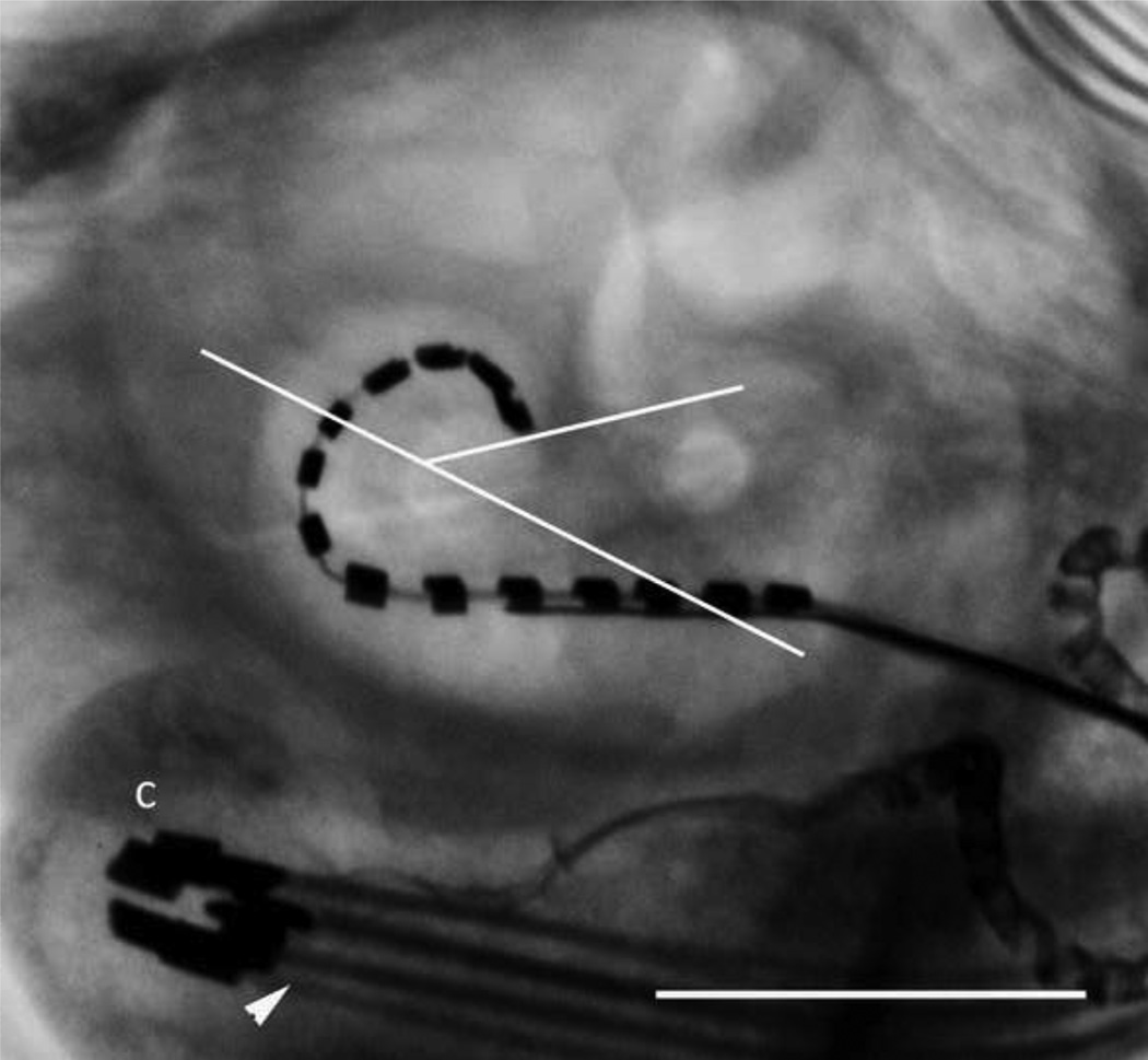
Figure 3 illustrates micro-focus radiographs from the six cadaveric cochleae used in the in vitro study (two straight electrode arrays, two HL24 arrays and two HL16 arrays). The average insertion depth was a 334.8° for the HL arrays and 175.5° for the standard array (Table 2). A similar insertion depth (322°) was recorded in the live-image of a cat chronically implanted with a HL14 electrode array (Fig. 4; the second animal in this series was not imaged as we are required to minimize the number of times an animal is anaesthetized in a chronic study).
Table 2.
Insertion Depth for each electrode array in this study
| Electrode array |
Insertion depth (degrees) |
Mean (SD) |
|---|---|---|
| Standard | 180 | 175.5 (6) |
| Standard | 171 | |
| Hybrid-L | 339 | 334.8 (21) |
| Hybrid-L | 309 | |
| Hybrid-L | 360 | |
| Hybrid-L | 331 |
Figure 4.
Live micro-focus radiograph of a HL electrode array in a chronically implanted cat. The electrode array was inserted to a depth of 322° – similar to the insertion depths recorded in the cadaveric studies. The leadwire (arrowhead) and its connector (C) located within the bulla are also illustrated. Scale bar = 5 mm.
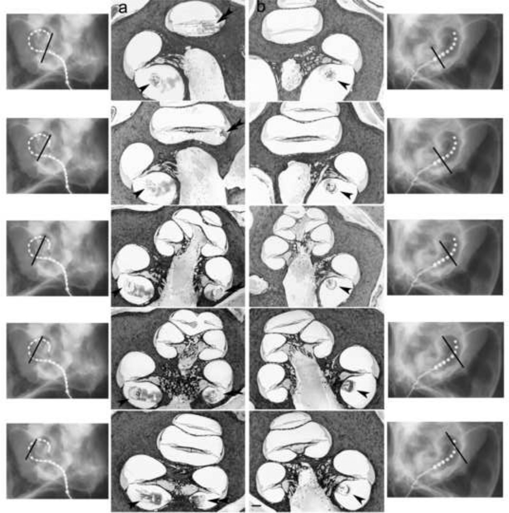
Figure 5 illustrates micrographs from two cochleae implanted as part of the in vitro study; the left cochlea was implanted with a HL24 array (Panel a) while the right cochlea was implanted with a standard array (Panel b). The approximate histological plane for each image is illustrated by the solid line in the accompanying radiographs. These histological images illustrate the anatomical position of each electrode array relative to the corresponding cochlear anatomy. A similar relationship between the site of the electrode array and the corresponding cochlear anatomy was observed in the other cochleae examined in this study.
Figure 5.
Serial micrographs from a left cochlea implanted with a Hybrid-L24 array (a) and a right cochlea implanted with a standard array (b). The location of the electrode array in the lower basal turn is illustrated by a single arrowhead while a double arrowhead illustrates an array in the upper basal turn. The approximate histological plane for each image is illustrated by the solid line in the accompanying radiographs. Scale bar = 500 µm.
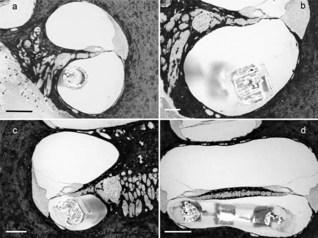
Higher power micrographs of representative cochleae are illustrated in Fig. 6. Examination of the serial histological sections from each cochleae showed that in all cases the electrode array was located in the scala tympani and there was no evidence of electrode insertion trauma to the basilar membrane, osseous spiral lamina or the spiral ligament on the lateral wall of the cochlea. Although both electrode arrays are designed as “free-fit” in the lower basal turn, the HL arrays occupied the majority of the scala tympani at its tip in the upper basal turn (Fig. 6c&d).
Figure 6.
Higher power micrographs of representative cochleae illustrating the location of the electrode array relative to cochlear anatomy. (a) a standard array located in the lower basal turn; (b) a Hybrid-L24 array located in the lower basal turn; (c) a Hybrid-L24 array located in the upper basal turn; and (d) a Hybrid-L24 array located at the intersection between the lower and upper basal turns. Although both electrode arrays occupy a small cross-sectional area of the lower basal turn scala tympani, the Hybrid-L24 array occupies the majority of the scala tympani in the upper basal turn. Despite this, there was no evidence of electrode insertion trauma. Scale bar = 500 µm.
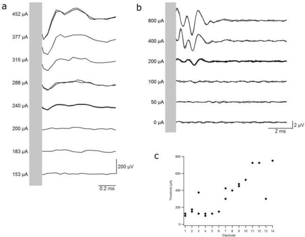
Electrically-evoked NRTs and EABRs (Fig. 7a&b) were readily evoked from both animals chronically implanted with the HL14 array. The response morphologies were similar to previous results evoked using the standard electrode array (e.g. Coco et al 2007). These responses were stable with no significant change in threshold over three months of chronic stimulation (paired t-Test, p > 0.2). EABRs evoked by HL electrodes exhibited a significant reduction in threshold with a more apical electrode location (Fig. 7c; Apical < Basal, One-Way ANOVA, p < 0.005). Moreover, mean thresholds to HL electrodes (331 µA, SEM = 49 µA, n = 19) were significantly lower compared with a cohort of animals implanted with the standard 8 Pt ring electrode array and stimulated using the same stimulus waveform (487 µA, SEM = 50 µA, n = 60 (Fallon et al. 2009a); t-Test, p < 0.05). Finally, there was no difference between NRT and EABR thresholds given the same electrode geometry and stimulus intensity (Paired t-Test, p > 0.23).
Figure 7.
Representative examples of (a) NRT and (b) EABR waveforms evoked from two animals chronically implanted with HL electrode arrays. Both set of responses were evoked using biphasic current pulses (25 µs/phase 8 µs inter-phase gap) delivered to a monopolar scala tympani electrode. The waveforms were similar in morphology to those evoked using the standard 8 Pt banded electrode array. Response thresholds remained stable over a three month monitoring period. (c) EABR thresholds immediately post implantation for the two chronically implanted animals. Thresholds to apical electrodes were generally significantly lower than more basal electrodes. Electrode 1 = most apical electrode, 14 = most basal.
4. Discussion
The present study demonstrates that Cochlear Ltd’s HL electrode arrays can be reliably used to achieve deep electrode insertion into the cochlea of cats with no evidence of electrode insertion trauma. In our hands the HL24 and HL16 arrays were inserted to a mean depth of 335° which is approximately 10.5 mm from the round window. A similar insertion depth (322°) was obtained in a chronically implanted animal implanted with a HL14 array and represents an insertion depth of ~50% the length of the scala tympani, placing the tip of the array at approximately the 4 kHz place (Greenwood 1990; Liberman 1982). This insertion depth is considerably greater than is routinely achieved using the standard electrode array (175° or ~6 mm from the round window). The tip of the standard electrode array is typically located at the 12 kHz cochlear place (Brown et al. 1992; Greenwood 1990; Liberman 1982). Importantly, both electrode designs showed no evidence of electrode insertion trauma when the electrode arrays were inserted to the point of first resistance.
The evoked potential data, collected from two animals implanted with HL14 electrode arrays over a three month period, demonstrated lower thresholds – particularly with more apical electrodes – compared with the standard Pt ring electrode array. Lower thresholds associated with more apical electrodes is presumably related to the closer proximity of the target neurons to the stimulating electrode due to the tapered nature of the scala tympani (Salt, 2010). The proximity of the electrode array to the corresponding spiral ganglion is evident in Figs. 5 & 6. These evoked potentials were similar in morphology to responses evoked using the standard electrode array. The data also demonstrated thresholds that were stable over the long-term. The ability to record electrically-evoked potentials is important in ensuring stimulus levels are set at intensities that activate the spiral ganglion in chronic animal studies. Collectively, these data indicate that the HL electrode provides a very effective electrode/neural interface when implanted into the cat scala tympani.
What do these findings mean for future experimental studies? Safely inserting electrode arrays to ~50% of the length of the scala tympani will enable researchers to address more effectively a number of important studies associated with cochlear implants. First, current focusing techniques to develop more localized patterns of neural excitation typically require the simultaneous stimulation of multiple electrodes along an array (Saoji et al., 2009; van den Honert and Kelsall 2007; Zierhofer & Schatzer, 2008). The ability to routinely insert 14 electrodes into the cochlea would result in a more accurate implementation of such novel stimulation strategies. Second, there are contradictory results on whether long-term electrical stimulation has a trophic effect on residual spiral ganglion neurons (e.g. compare Leake et al. 1991 and Shepherd et al. 2005). Rather than stimulating within the lower basal turn, electrode arrays that cover a broader region of the cochlea would be of significance in addressing this issue as they can selectively stimulate a far greater proportion of the spiral ganglion population and more accurately reflect the situation experienced clinically. Third, plasticity studies in experimental animals have, to date, been restricted to examining relatively localised sectors within central auditory structures that correspond to that region of the cochlea adjacent to the electrode array (Fallon et al. 2009a; Klinke et al., 1999; Ryugo et al., 2005). An electrode array that can be reliably inserted deeper within the scala tympani would produce more spatially extensive plastic reorganisation within central auditory structures in response to cochlear stimulation. These electrode arrays would also provide a more realistic model to investigate both the histopathological and plastic changes associated with combined electric and acoustic stimulation of partial hearing cochleae (Coco et al. 2007; Fallon et al., 2009b). Fourth, consistently deep insertion of an electrode array would also be beneficial to the study of bilateral cochlear implantation on the developing brain. Having a similar depth of insertion across both ears and the ability to excite more apical regions of the cochleae is expected to produce more real-world listening situations considered necessary to drive this form of plastic change (Hartley et al. 2010). Finally, given that the electrode array is manufactured using the same medical grade materials as used clinically, these arrays are suitable for use in chronic in vivo studies.
It is important to note that while we saw no evidence of electrode insertion trauma in the present study, the HL electrode arrays must not be inserted beyond the point of first resistance as it is clear from this study that at an insertion depth in the cat cochleae of more than 10 mm from the round window the tip of this array occupies the majority of the cross-section of the scala tympani. A reduction in the dimensions of the tip of the array would be needed if one is to develop electrode arrays that result in even great electrode insertion depths in this species.
Supplementary Material
Research Highlights.
New Hybrid-L24 and Hybrid-L16 arrays can be inserted further into the cochlea
Arrays can be inserted up to 50% the length of cochlea
Deeper insertion can be achieved with no trauma
HL electrode arrays exhibit significantly lower thresholds than a standard 8 ring array
Evoked potential thresholds remain stable over a three month chronic stimulation period.
Acknowledgements
We are grateful for funding support from the National Institutes of Health NIDCD (HHS-N-263-2007-00053-C), Cochlear Ltd, the NH&MRC of the Australian Government and the Victorian State Government through their Operational Infrastructure Support scheme. We thank Ms. Helen Feng and Godofredo Timbol for their contributions to this study and acknowledge the HEARing Cooperative Research Centre for access to the Microfocus X-ray Imaging facility.
Footnotes
Publisher's Disclaimer: This is a PDF file of an unedited manuscript that has been accepted for publication. As a service to our customers we are providing this early version of the manuscript. The manuscript will undergo copyediting, typesetting, and review of the resulting proof before it is published in its final citable form. Please note that during the production process errors may be discovered which could affect the content, and all legal disclaimers that apply to the journal pertain.
References
- Briggs RJ, Tykocinski M, Xu J, Risi F, Svehla M, Cowan R, Stover T, Erfurt P, Lenarz T. Comparison of round window and cochleostomy approaches with a prototype hearing preservation electrode. Audiol Neurootol. 2006;11(Suppl 1):42–48. doi: 10.1159/000095613. [DOI] [PubMed] [Google Scholar]
- Brown M, Shepherd RK, Webster WR, Martin RL, Clark GM. Cochleotopic selectivity of a multichannel scala tympani electrode array using the 2-deoxyglucose technique. Hear Res. 1992;59:224–240. doi: 10.1016/0378-5955(92)90119-8. [DOI] [PubMed] [Google Scholar]
- Clark GM, Shepherd RK, Patrick JF, Black RC, Tong YC. Design and fabrication of the banded electrode array. Ann N Y Acad Sci. 1983;405:191–201. doi: 10.1111/j.1749-6632.1983.tb31632.x. [DOI] [PubMed] [Google Scholar]
- Coco A, Epp SB, Fallon JB, Xu J, Millard RE, Shepherd RK. Does cochlear implantation and electrical stimulation affect residual hair cells and spiral ganglion neurons? Hear Res. 2007;225:60–70. doi: 10.1016/j.heares.2006.12.004. [DOI] [PMC free article] [PubMed] [Google Scholar]
- Fallon JB, Irvine DR, Shepherd RK. Cochlear implant use following neonatal deafness influences the cochleotopic organization of the primary auditory cortex in cats. J Comp Neurol. 2009a;512:101–114. doi: 10.1002/cne.21886. [DOI] [PMC free article] [PubMed] [Google Scholar]
- Fallon JB, Shepherd RK, Brown M, Irvine DR. Effects of neonatal partial deafness and chronic intracochlear electrical stimulation on auditory and electrical response characteristics in primary auditory cortex. Hear Res. 2009b;257:93–105. doi: 10.1016/j.heares.2009.08.006. [DOI] [PMC free article] [PubMed] [Google Scholar]
- Greenwood DD. A cochlear frequency-position function for several species--29 years later. Journal of the Acoustical Society of America. 1990;87:2592–2605. doi: 10.1121/1.399052. [DOI] [PubMed] [Google Scholar]
- Hartley DE, Vongpaisal T, Xu J, Shepherd RK, King AJ, Isaiah A. Bilateral cochlear implantation in the ferret: A novel animal model for behavioral studies. J Neurosci Methods. 2010;190:214–228. doi: 10.1016/j.jneumeth.2010.05.014. [DOI] [PMC free article] [PubMed] [Google Scholar]
- Hartmann R, Shepherd RK, Heid S, Klinke R. Response of the primary auditory cortex to electrical stimulation of the auditory nerve in the congenitally deaf white cat. Hearing Research. 1997;112:115–133. doi: 10.1016/s0378-5955(97)00114-7. [DOI] [PubMed] [Google Scholar]
- Hartshorn DO, Miller JM, Altschuler RA. Protective effect of electrical stimulation in the deafened guinea pig cochlea. Archives of Otolaryngology - Head and Neck Surgery. 1991;104:311–319. doi: 10.1177/019459989110400305. [DOI] [PubMed] [Google Scholar]
- Hatsushika S, Shepherd RK, Tong YC, Clark GM, Funasaka S. Dimensions of the scala tympani in the human and cat with reference to cochlear implants. Annals of Otology, Rhinology and Laryngology. 1990;99:871–876. doi: 10.1177/000348949009901104. [DOI] [PubMed] [Google Scholar]
- Hochmair-Desoyer I, Hochmair ES. An eight channel scala tympani electrode for auditory prostheses. IEEE Trans Biomed Eng. 1980;27:44–50. doi: 10.1109/TBME.1980.326691. [DOI] [PubMed] [Google Scholar]
- Hsu WC, Campos-Torres A, Portier F, Lecain E, Van Den Abbeele T, De Waele C, Huy PTB. Cochlear electrical stimulation: Influence of age of implantation on Fos immunocytochemical reactions in inferior colliculi and dorsal cochlear nuclei of the rat. Journal of Comparative Neurology. 2001;438:226–238. doi: 10.1002/cne.1311. [DOI] [PubMed] [Google Scholar]
- Igarashi M, Mahon RC, Jr, Konishi S. Comparative measurements of cochlear apparatus. Journal of Speech & Hearing Research. 1968;11:229–235. doi: 10.1044/jshr.1102.229. [DOI] [PubMed] [Google Scholar]
- Klinke R, Kral A, Heid S, Tillein J, Hartmann R. Recruitment of the auditory cortex in congenitally deaf cats by long-term cochlear electrostimulation. Science. 1999;285:1729–1733. doi: 10.1126/science.285.5434.1729. [DOI] [PubMed] [Google Scholar]
- Kral A, Hartmann R, Tillein J, Heid S, Klinke R. Hearing after congenital deafness: central auditory plasticity and sensory deprivation. Cereb Cortex. 2002;12:797–807. doi: 10.1093/cercor/12.8.797. [DOI] [PubMed] [Google Scholar]
- Leake PA, Hradek GT, Rebscher SJ, Snyder RL. Chronic intracochlear electrical stimulation induces selective survival of spiral ganglion neurons in neonatally deafened cats. Hear Res. 1991;54:251–271. doi: 10.1016/0378-5955(91)90120-x. [DOI] [PubMed] [Google Scholar]
- Leake PA, Snyder RL, Rebscher SJ, Moore CM, Vollmer M. Plasticity in central representations in the inferior colliculus induced by chronic single- vs. two-channel electrical stimulation by a cochlear implant after neonatal deafness. Hear Res. 2000;147:221–241. doi: 10.1016/s0378-5955(00)00133-7. [DOI] [PubMed] [Google Scholar]
- Liberman MC. The cochlear frequency map for the cat: labeling auditory-nerve fibers of known characteristic frequency. Journal of the Acoustical Society of America. 1982;72:1441–1449. doi: 10.1121/1.388677. [DOI] [PubMed] [Google Scholar]
- Miller CA, Woodruff KE, Pfingst BE. Functional responses from guinea pigs with cochlear implants. I. Electrophysiological and psychophysical measures. Hear Res. 1995;92:85–99. doi: 10.1016/0378-5955(95)00204-9. [DOI] [PubMed] [Google Scholar]
- Rebscher SJ, Hetherington AM, Snyder RL, Leake PA, Bonham BH. Design and fabrication of multichannel cochlear implants for animal research. J Neurosci Methods. 2007;166:1–12. doi: 10.1016/j.jneumeth.2007.05.013. [DOI] [PMC free article] [PubMed] [Google Scholar]
- Rebscher SJ, Hetherington A, Bonham B, Wardrop P, Whinney D, Leake PA. Considerations for design of future cochlear implant electrode arrays: electrode array stiffness, size, and depth of insertion. J Rehabil Res Dev. 2008;45:731–747. doi: 10.1682/jrrd.2007.08.0119. [DOI] [PMC free article] [PubMed] [Google Scholar]
- Ryugo DK, Kretzmer EA, Niparko JK. Restoration of auditory nerve synapses in cats by cochlear implants. Science. 2005;310:1490–1492. doi: 10.1126/science.1119419. [DOI] [PubMed] [Google Scholar]
- Ryugo DK, Baker CA, Montey KL, Chang LY, Coco A, Fallon JB, Shepherd RK. Synaptic plasticity after chemical deafening and electrical stimulation of the auditory nerve in cats. J Comp Neurol. 2010;518:1046–1063. doi: 10.1002/cne.22262. [DOI] [PMC free article] [PubMed] [Google Scholar]
- Saoji AA, Litvak LM, Hughes ML. Excitation patterns of simultaneous and sequential dual-electrode stimulation in cochlear implant recipients. Ear and Hearing. 2009;30:559–567. doi: 10.1097/AUD.0b013e3181ab2b6f. [DOI] [PubMed] [Google Scholar]
- Salt AN. Cochlear Fluids Research Laboratory. 2010 [Online] http://oto2.wustl.edu/cochlea/ (verified 15 July) [Google Scholar]
- Shepherd RK, McCreery DB. Basis of electrical stimulation of the cochlea and the cochlear nucleus. Adv Otorhinolaryngol. 2006;64:186–205. doi: 10.1159/000094652. [DOI] [PubMed] [Google Scholar]
- Shepherd RK, Clark GM, Black RC. Chronic electrical stimulation of the auditory nerve in cats. Physiological and histopathological results. Acta Oto- Laryngologica. 1983;399(Supplement):19–31. doi: 10.3109/00016488309105589. [DOI] [PubMed] [Google Scholar]
- Shepherd RK, Roberts LA, Paolini AG. Long-term sensorineural hearing loss induces functional changes in the rat auditory nerve. Eur J Neurosci. 2004;20:3131–3140. doi: 10.1111/j.1460-9568.2004.03809.x. [DOI] [PubMed] [Google Scholar]
- Shepherd RK, Coco A, Epp SB, Crook JM. Chronic depolarization enhances the trophic effects of brain-derived neurotrophic factor in rescuing auditory neurons following a sensorineural hearing loss. J Comp Neurol. 2005;486:145–158. doi: 10.1002/cne.20564. [DOI] [PMC free article] [PubMed] [Google Scholar]
- Tykocinski M, Cohen LT, Pyman BC, Roland T, Jr, Treaba C, Palamara J, Dahm MC, Shepherd RK, Xu J, Cowan RS, Cohen NL, Clark GM. Comparison of electrode position in the human cochlea using various perimodiolar electrode arrays. Am J Otol. 2000;21:205–211. doi: 10.1016/s0196-0709(00)80010-1. [DOI] [PubMed] [Google Scholar]
- van den Honert C, Kelsall DC. Focused intracochlear electric stimulation with phased array channels. J Acoust Soc Am. 2007;121:3703–3716. doi: 10.1121/1.2722047. [DOI] [PubMed] [Google Scholar]
- Xu J, Cowan R. Role of micro-focus radiography and fluoroscopy in developing improved electrode arrays for cochlear implants. Cochlear Implants Int. 2005;6(Suppl 1):8–10. doi: 10.1179/cim.2005.6.Supplement-1.8. [DOI] [PubMed] [Google Scholar]
- Xu J, Shepherd RK, Millard RE, Clark GM. Chronic electrical stimulation of the auditory nerve at high stimulus rates: a physiological and histopathological study. Hearing Research. 1997;105:1–29. doi: 10.1016/s0378-5955(96)00193-1. [DOI] [PubMed] [Google Scholar]
- Xu J, Xu SA, Cohen LT, Clark GM. Cochlear view: postoperative radiography for cochlear implantation. Am J Otol. 2000;21:49–56. [PubMed] [Google Scholar]
- Xu J, Briggs R, Tykocinski M, Newbold C, Risi F, Cowan R. Micro-focus fluoroscopy - a great tool for electrode development. Cochlear Implants Int. 2009;10(Suppl 1):115–119. doi: 10.1179/cim.2009.10.Supplement-1.115. [DOI] [PubMed] [Google Scholar]
- Xu J, Stevenson AW, Gao D, Tykocinski M, Lawrence D, Wilkins SW, Clark GM, Saunders E, Cowan RS. The role of radiographic phase-contrast imaging in the development of intracochlear electrode arrays. Otol Neurotol. 2001;22:862–868. doi: 10.1097/00129492-200111000-00026. [DOI] [PubMed] [Google Scholar]
- Zierhofer CM, Schatzer R. Simultaneous intracochlear stimulation based on channel interaction compensation: analysis and first results. IEEE Trans Biomed Eng. 2008;55:1907–1916. doi: 10.1109/TBME.2008.919839. [DOI] [PubMed] [Google Scholar]
Associated Data
This section collects any data citations, data availability statements, or supplementary materials included in this article.


