

Abstract
Complex 3-D defects of the facial skeleton are difficult to reconstruct with freehand carving of autogenous bone grafts. Onlay bone grafts are hard to carve and are associated with imprecise graft-bone interface contact and bony resorption. Autologous cartilage is well established in ear reconstruction as it is easy to carve and is associated with minimal resorption. In the present study, we aimed to reconstruct the hypoplastic orbitozygomatic region in a patient with left hemifacial microsomia using computer-aided design and rapid prototyping to facilitate costal cartilage carving and grafting. A three-step process of (1) 3-D reconstruction of the computed tomographic image, (2) mirroring the facial skeleton, and (3) modeling and rapid prototyping of the left orbitozygomaticomalar region and reconstruction template was performed. The template aided in donor site selection and extracorporeal contouring of the rib cartilage graft to allow for an accurate fit of the graft to the bony model prior to final fixation in the patient. We are able to refine the existing computer-aided design and rapid prototyping methods to allow for extracorporeal contouring of grafts and present rib cartilage as a good alternative to bone for autologous reconstruction.
Keywords: computer-aided design (CAD), rapid prototyping (RP), costal cartilage graft, orbitozygomatic deformity
Complex bony deformities of the craniofacial skeleton may result from congenital anomalies or be acquired from trauma, infection, and tumor resection.1 Reconstruction of craniofacial bony deformities is difficult as these deformities are three-dimensionally complex in size and shape. To date, bony defects have been reconstructed with bone grafts, cartilage grafts, and alloplastic implants. The use of autogenous bone and cartilage is the gold standard for facial reconstruction.2,3 Freehand carving is required for bone and cartilage grafts, and this may be associated with problems of poor fit between the bone-implant interface, irregular contours, palpable edges, and persistent asymmetry.1 The advent of computer-assisted design or computer-aided design (CAD) and rapid prototyping (RP) techniques have allowed for the fabrication of 3-D models of deformed bone4 and customized templates based on mirror imaging of the contralateral normal side onto the deformed side (for example, see Eufinger and Saylor,5 Hierl et al,6 Rah,7 Juergens et al8). These templates may be used as customized implants5,6,7,8 or to contour bone grafts. Autologous material is the gold standard for bony reconstruction and avoids the complications of alloplastic implants, such as infection, displacement, and extrusion.9,10 Bone is difficult to carve in fine detail1 and is associated with resorption. Resorption is generally not seen in cartilage grafts, and the use of moderate-size cartilage grafts is well established in ear reconstruction. There have been no reports on the use of CAD templates to aid the harvesting and carving of autogenous cartilage grafts.
We propose that autogenous cartilage is a valuable material for volume replacement and contour augmentation in moderate-size facial defects. We present a novel combination of CAD and RP to fashion models of the deformed orbitozygomaticomalar region and of the proposed 3-D template for bony reconstruction. The combined use of the models aids in donor site selection and extracorporeal cartilage carving to achieve a good fit of the graft onto the model prior to final placement in the patient.
Materials and Methods
The Case Study
The patient was a 21-year-old woman with craniofacial microsomia secondary to Goldenhar syndrome. She had hypoplasia of the left orbitozygomaticomalar region; left mandibular, ramus, and condyle were absent (Pruzansky type 3); left microtia; left VII to XII nerve palsy; and left soft tissue deficit. She also had a left microform cleft lip and nose deformity. In childhood she had undergone costochondral rib graft for reconstruction of the left mandibular ramus and condyle, resection of left epibulbar dermoid and repair of left macrostomia. Her current reconstruction focused on the correction of her upper- and mid-face deformities, namely, restoration of left orbitozygomaticomalar bony contours, correction of left antimongoloid slant, correction of low brow position, left microform cleft lip repair, and correction of nasal tip bulbosity. As the patient declined alloplastic reconstruction to the complex left orbitozygomatic-malar region, the decision was made for CAD and RP to assist in the creation of a template to facilitate intraoperative harvesting and contouring of the cartilaginous rib graft.
Surgery Planning for the Implants
The aim of the surgical procedure was to match the hypoplastic left orbitozygomaticomalar region with the right side to improve midface symmetry. To assess the contour and volume differences, the mirror image of the normal right orbitozygomaticomalar region was superimposed onto the left side. The presurgical planning consists of three steps: 3-D reconstruction from computed tomographic (CT) imaging, mirroring of the facial skeleton, and modeling and RP of the orbitozygomaticomalar region and the reconstruction template.
3-D Reconstruction from CT Imaging
The CT scan images of the patient’s skeleton in Digital Imaging and Communications in Medicine (DICOM) file format were imported into medical image processing software called Mimics v13.0 (Materialise, Leuven, Belgium). The CT data were then converted to a mask of the deformed facial skeleton created using thresholding technique with default setting of Hounsfield units (Fig. 1). Different algorithms such as thresholding, mathematical morphology, and region growing and smoothing techniques were utilized to automatically segment the skull bone in the CT data. However, the noise or unwanted pixels, which were still connected with the facial skeleton due to low resolution of the CT scan, were difficult to be isolated. Therefore, manual subtraction of the noise pixels under the supervision of the surgeon was carried out to further segment the facial skeleton, and eventually the 3-D model of the original distorted facial skeleton was reconstructed (Fig. 1).
Figure 1.

Computed tomography data with the yellow mask showing the original distorted facial skeleton and the cyan mask showing the reflected left skull from the healthy right half.
Mirroring
The aim of the surgery is to restore orbitozygomaticomalar symmetry; hence, the normal right orbitozygomaticomalar region was mirrored with respect to the midsagittal plane. In view of the facial torticollis and asymmetry, standardized bony landmarks were used to delineate the midsagittal plane.11 The anatomic landmarks chosen were the foramen cecum, the posterior extremity of the sphenoid crest, and the middle point between both apophysis clinoid (Fig. 2).
Figure 2.

Computed tomography data (in axial view) showing anatomic landmarks for symmetry. (A) Foramen cecum. (B) Posterior extremity of the sphenoid crest.
The mirroring was done in HyperMesh v10.0 (Altair HyperWorks, Troy, MI) whereby the model of the normal right half was imported as stereolithography (STL) format and then reflected to the left-hand side (Fig. 1). Following the mirroring, the meshes of reflected left facial skeleton were imported back into Mimics in STL format to generate the mask of the reflected left half. As such, this reverse engineering method enabled us to reconstruct a 3-D model of a selected skull. In this case, the reflected facial skeleton on the patient’s left side was reflected from the normal right half of the skull.
Modeling and RP of the Implant
The mask of the implant could be generated using Boolean operation of subtracting the original skull from the mirrored one. In this study, we only focused on the surgical procedure for the patient’s left orbitozygomaticomalar region. The masks of both the original skull and implant were further segmented in Mimics to remove the unwanted pixels so as to isolate just the left orbitozygomaticomalar region. The boundaries of the segmented region formed landmarks, and these were the distal end of the zygomatic arch posteriorly, infraorbital nerve foramen anteriorly, cephalad edge of the supraorbital nerve foramen superiorly, and inferior edge of the zygoma inferiorly (Fig. 3). After having the left zygomatic region isolated, the next step was to remove the interior skull tissues that were not useful for producing the implant.
Figure 3.

The reconstructed models of the skull and the implant. (A) Original distorted skull (in yellow) of the patient while the pink and the purple pieces represent the zygomatic region of the facial skeleton. (B) Enlarged view of zygomatic region where the pink piece represents the distorted zygomatic region and the purple represents the zygomatic implant. The landmarks for defining the region of interest are shown in the figure.
The completed models of the zygomatic skull and implant were then manufactured using RP technology with PolyJet Matrix (Objet Ltd., Billerica, MA) which were based on a layered principle (Fig. 4). It started by cutting a virtual model in a digital environment into a set of thin parallel slices. The slices, representing 2-D images of the cross sections of the model, were transmitted to a “3-D printer” where they were “printed” one over another to form a 3-D object. As for the material, a translucent acrylic-based photopolymer material, FullCure Transparent (Objet Ltd., Billerica, MA), was chosen for making both the zygomatic skull and implant as the material was light, tough, and most importantly biocompatible.
Figure 4.

Computed-aided drafting and rapid prototyping produced 3-D models of the deformed left orbitozygomaticomalar region (left) and template (right).
After removing from the 3-D printer, the “printed” parts were sequentially cleansed with water jet, soaking in 1% caustic soda at 45°C and then analytical-grade isopropyl alcohol to remove excess support material. The final biocompatible models of left orbitozygomaticomalar skeleton and template were then gas sterilized and ready for intraoperative use (Fig. 4).
The Surgical Procedure
The brow and left zygoma were accessed via the old bicoronal incision and the left infraorbital region was exposed via a subciliary incision. Cartilage was harvested from the ipsilateral chest wall. The 3-D template was placed over the left costal margin and the best fit found with the template rotated 180 degrees over the seventh to eighth cartilaginous synchondrosis. Care was taken to preserve the perichondrium over the external rib surface. An additional 5 cm of the eighth rib was harvested for nasal augmentation, and the floating end of the ninth rib cartilage was harvested for the columellar strut graft. The synchondrotic segment was placed over the left orbit model. The inner orbital margin was inked and the excess excised with rounding of the inner edges. The segment over the supraorbital region and zygoma was contoured to fit the external surface of the left orbit model (Fig. 5). The remnant cartilage was placed on the infraorbital and malar region. This was secured by 36-gauge wire. Drill holes were made from the 12 o’clock to 6 o’clock position of the left orbit, and 36-gauge wires were placed through the holes. The graft was placed via the bicoronal incision and secured with the preplanned wires (Fig. 6). Ancillary procedures were lateral canthoplasty, open rhinoplasty, and costochondral rib graft for nasal augmentation, correction of microform cleft lip, and left nasal sill reduction (Fig. 6). At 1-year follow-up, CT scan showed minimal resorption (Fig. 7), and the contours of the midface were smooth (Fig. 8).
Figure 5.
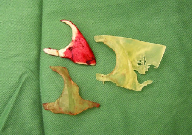
The rib graft placed next to the 3-D model of the implants produced by rapid prototyping.
Figure 6.
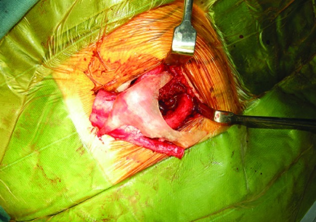
The rib graft during the surgery.
Figure 7.

Operative sequence and planning showing (left) the preoperative deformity, (center) the proposed planning, and (right) the 1-year postoperative computed tomography scan and facial dimensions showing a smooth external contour and minimal resorption of the rib graft to the orbitozygomatic region. The graft was secured with wires.
Figure 8.

Preoperative and 1-year postoperative pictures showing smooth midface contours. The patient had undergone left ptosis correction 6 months after the initial surgery.
Discussion
Complex 3-D defects of bone and soft tissue can result from tumor extirpation, trauma, and congenital anomalies.1 Accurate preoperative assessment of the contour and volume of these defects is greatly aided by 3-D imaging.1,12,13,14,15,16 Superimposition of the mirror image of the normal contralateral side allows for calculation of the anatomic defect and the construction of a 3-D model with a computer-controlled milling device.1 These anatomically precise prostheses have been used as guides for removing tissue,1,17,18 for alloplastic implantation,1 and as templates to aid in donor site selection and the contouring of autogenous bone grafts to the cranium.1 The benefits of 3-D imaging analysis and prostheses fabrication technology have translated into the benefits of decreased operating time and greater surgical accuracy.1 The present approach was intended to broaden the experience with computer-aided analysis and design.
Autologous tissue is the gold standard for reconstruction. Generally, bone grafts rather than cartilage grafts have been used for facial and cranial bone defects.1 Bone grafts are not ideal for the orbitozygomatic region, as it is very difficult to carve a complex shape out of hard bone to get an accurate fit without palpable edges and irregularity.19 However, as an onlay graft, there is increased risk of bony resorption. Although alloplastic implants have been advocated for volume and contour restoration of complex bony defects,20,21,22 they carry significant risks of infection,1,10,23 slippage,1,10,19 extrusion,10,19 malposition,10 asymmetry, hematoma, infection, nerve dysfunction, bone resorption, and soft tissue distortion.10 To avoid the problems with alloplastic implantation and to facilitate ease of carving a complex graft shape, we decided on cartilage as the material of choice in our patient. The use of moderate-size cartilage grafts and its carving technique is well established for ear reconstruction, and there is minimal resorption with cartilage.24,25,26
The most significant advantage of CAD-RP technology is the accuracy of the assessment of the irregular bony contour and the creation of the interior template surface to conform to the underlying bone.19 Previous limitations of CT resolution and software analysis of complex spatial relationships limited the accuracy of implant design, requiring an actual wax template to be created that would restore the bony contours.1,19 Fine details of surface irregularities cannot be well molded, and there were residual issues with accurate implant/bone fit. We now combine significant improvements in fine-cut imaging with computer analysis to allow the creation of a model of the actual deformity and the template needed for reconstruction to allow for easy harvesting and complete ex vivo contouring prior to in vivo placement. Particular care was taken to preserve the perichondrium over the external rib surface to provide a smooth external zygomatic contour and to taper the edges of the graft around the orbital rim to limit visible edges and palpable irregularities.
Conclusion
Ancient Chinese lyrics tell us, “Holding the handle of an axe to carve out the handle of a new axe, the model sample is not too far away.” The reported procedure, incorporating imaging and CAD in producing 3-D digital model of the implant and RP to produce a physical model of the implant, facilitates the creation of a rib graft that will conform better to the complex geometry of the zygomatic region. The 3-D model produced by the RP will also assist the surgeon in selecting the donor site in the thoracic rib cage for harvesting the rib graft. The continuous improvement in the capability of imaging segmentation software such as Mimics will shorten and simplify this process. The possibility of having tabletop RP equipment will also make it feasible for surgeons to perform the whole procedure within the same operating theatre or clinic.
Acknowledgment
The authors would like to acknowledge the support by a grant from the Swiss-based CMF Clinical Priority Program of the AO Foundation under the project number C-09-2L.
References
- 1.Toth B A, Ellis D S, Stewart W B. Computer-designed prostheses for orbitocranial reconstruction. Plast Reconstr Surg. 1988;81:315–324. doi: 10.1097/00006534-198803000-00001. [DOI] [PubMed] [Google Scholar]
- 2.Tessier P Kawamoto H Matthews D et al. Autogenous bone grafts and bone substitutes—tools and techniques: I. A 20,000-case experience in maxillofacial and craniofacial surgery Plast Reconstr Surg 20051165, Suppl6S–24S.; discussion 92S–94S [DOI] [PubMed] [Google Scholar]
- 3.Tessier P Kawamoto H Matthews D et al. Taking long rib grafts for facial reconstruction—tools and techniques: III. A 2900-case experience in maxillofacial and craniofacial surgery Plast Reconstr Surg 20051165, Suppl38S–46S.; discussion 92S–94S [DOI] [PubMed] [Google Scholar]
- 4.Ewers R, Schicho K. Augmented reality telenavigation in cranio maxillofacial oral surgery. Stud Health Technol Inform. 2009;150:24–25. [PubMed] [Google Scholar]
- 5.Eufinger H Saylor B Computer-assisted prefabrication of individual craniofacial implants AORN J 200174648–654.; quiz 655–656, 658–662 [DOI] [PubMed] [Google Scholar]
- 6.Hierl T, Wollny G, Schulze F P. et al. CAD-CAM implants in esthetic and reconstructive craniofacial surgery. J Comput Informat Technol. 2006;1:65–70. [Google Scholar]
- 7.Rah D K. Art of replacing craniofacial bone defects. Yonsei Med J. 2000;41:756–765. doi: 10.3349/ymj.2000.41.6.756. [DOI] [PubMed] [Google Scholar]
- 8.Juergens P, Krol Z, Zeilhofer H F. et al. Computer simulation and rapid prototyping for the reconstruction of the mandible. J Oral Maxillofac Surg. 2009;67:2167–2170. doi: 10.1016/j.joms.2009.04.104. [DOI] [PubMed] [Google Scholar]
- 9.Hasson O, Levi G, Conley R. Late infections associated with alloplastic facial implants. J Oral Maxillofac Surg. 2007;65:321–323. doi: 10.1016/j.joms.2005.11.066. [DOI] [PubMed] [Google Scholar]
- 10.Cuzalina L A, Hlavacek M R. Complications of facial implants. Oral Maxillofac Surg Clin North Am. 2009;21:91–104, vi–vii. doi: 10.1016/j.coms.2008.10.009. [DOI] [PubMed] [Google Scholar]
- 11.Maubleu S, Marecaux C, Chabanas M, Payan Y, Boutault F. Computer-aided planning for zygomatic bone reconstruction in maxillofacial traumatology. In Proceedings of the 2nd International Conference Surgetica. 2006. pp. 405–411.
- 12.Hemmy D C, Tessier P L. CT of dry skulls with craniofacial deformities: accuracy of three-dimensional reconstruction. Radiology. 1985;157:113–116. doi: 10.1148/radiology.157.1.3929326. [DOI] [PubMed] [Google Scholar]
- 13.Forbes G, Gehring D G, Gorman C A, Brennan M D, Jackson I T. Volume measurements of normal orbital structures by computed tomographic analysis. AJR Am J Roentgenol. 1985;145:149–154. doi: 10.2214/ajr.145.1.149. [DOI] [PubMed] [Google Scholar]
- 14.Marsh J L, Vannier M W. The “third” dimension in craniofacial surgery. Plast Reconstr Surg. 1983;71:759–767. doi: 10.1097/00006534-198306000-00002. [DOI] [PubMed] [Google Scholar]
- 15.Jackson I T, Bite U. Three-dimensional computed tomographic scanning and major surgical reconstruction of the head and neck. Mayo Clin Proc. 1986;61:546–555. doi: 10.1016/s0025-6196(12)62003-5. [DOI] [PubMed] [Google Scholar]
- 16.Vannier M W, Marsh J L, Warren J O. Three dimensional CT reconstruction images for craniofacial surgical planning and evaluation. Radiology. 1984;150:179–184. doi: 10.1148/radiology.150.1.6689758. [DOI] [PubMed] [Google Scholar]
- 17.Woolson S T, Dev P, Fellingham L L, Vassiliadis A. Three-dimensional imaging of bone from computerized tomography. Clin Orthop Relat Res. 1986;202:239–248. [PubMed] [Google Scholar]
- 18.Young S W White D N Kaplan E N et al. An NMR and CT contour finding algorithm for automated volume calculation, 3-dimensional CRT scan display and prostheses millingPaper presented at: RSNA 69th Annual Meeting; November 1983; Chicago, Illinois
- 19.Binder W J Kaye A Reconstruction of posttraumatic and congenital facial deformities with three-dimensional computer-assisted custom-designed implants Plast Reconstr Surg 199494775–785.; discussion 786–787 [PubMed] [Google Scholar]
- 20.Romano J J, Iliff N T, Manson P N. Use of Medpor porous polyethylene implants in 140 patients with facial fractures. J Craniofac Surg. 1993;4:142–147. doi: 10.1097/00001665-199307000-00007. [DOI] [PubMed] [Google Scholar]
- 21.Yaremchuk M J. Facial skeletal reconstruction using porous polyethylene implants. Plast Reconstr Surg. 2003;111:1818–1827. doi: 10.1097/01.PRS.0000056866.80665.7A. [DOI] [PubMed] [Google Scholar]
- 22.Goh R CW, Chang C N, Lin C L, Lo L J. Customised fabricated implants after previous failed cranioplasty. J Plast Reconstr Aesthet Surg. 2010;63:1479–1484. doi: 10.1016/j.bjps.2009.08.010. [DOI] [PubMed] [Google Scholar]
- 23.Miyasaka M, Tanaka R, Hanai U, Yamazaki A, Iida M, Akamatsu T. A case of chronic infection 28 years after silicone orbital implant. Tokai J Exp Clin Med. 2008;33:35–38. [PubMed] [Google Scholar]
- 24.Brent B Auricular repair with autogenous rib cartilage grafts: two decades of experience with 600 cases Plast Reconstr Surg 199290355–374.; discussion 375–376 [PubMed] [Google Scholar]
- 25.Firmin F. [Reconstruction of the pinna in cases of microtia] Rev Laryngol Otol Rhinol (Bord) 1997;118:11–16. [PubMed] [Google Scholar]
- 26.Nagata S. Alternative surgical methods of treatment for the constricted ear. Clin Plast Surg. 2002;29:301–315. doi: 10.1016/s0094-1298(01)00015-3. [DOI] [PubMed] [Google Scholar]