Abstract
Background:
The contribution of lower limb rotational malalignment to patellofemoral pain and instability has been well recognized. The purpose of the present study is to review the role of computed tomography (CT) and magnetic resonance imaging (MRI) in assessment of abnormal rotational alignment of lower limb.
Evidence Acquisition:
An analysis of all available literature in the English language through 2010 was performed to provide data on a comparison between MRI and CT—specifically, the techniques and normative values used to determine abnormal lower limb alignment.
Results:
CT and MRI are highly accurate in defining abnormal alignment of the lower limb. Determination of axis of femoral anteversion in proximal femur has been the subject of debate in the literature. The determination of distal femoral condylar axis, proximal tibial axis and distal tibial axis are less controversial.
Conclusions:
CT and MRI are both used for assessing the rotational abnormalities of the femur and tibia during evaluation for patellofemoral disorders. MRI has an advantage over CT because femoral anteversion measurements are more accurate and ionizing radiation is avoided. A standardized protocol defining the level and axes for measurement of femoral and tibial alignment indices should be used to maintain consistency in measurements.
Keywords: patellofemoral pain, femoral anteversion, tibial torsion, magnetic resonance imaging, computed tomography
The contribution of lower limb rotational malalignment to patellofemoral pain and instability has been well recognized. One of the key components determining the orientation of the flexion-extension axis of the knee joint and patellofemoral tracking is the rotational alignment of femur and tibia. Increased femoral anteversion leads to an internally rotated gait unless an accompanying external tibial torsion rotates the leg outward to maintain a normal foot progression angle during gait.49 The combination of increased femoral anteversion and increased external tibial torsion has been termed miserable malalignment syndrome,4,23 a spectrum that includes squinting patellae, genu varum, genu recurvatum, patella alta, and pronated feet (Figure 1). This rotational malalignment is in contrast to extensor mechanism malalignment, which was popularized by Hughston.21 In the presence of rotational malalignment, 2 issues become important in terms of surgical planning. First, the increase in femoral anteversion produces high lateral–directed patellofemoral joint forces and pain not relieved by performing a proximal or distal realignment procedure. Second, there is an increase in the Q angle, leading to an increase in the lateral-directed force on the patella (Figures 2 and 3). When the patient remains symptomatic because of patellofemoral pain or instability in presence of an increased Q angle, a frequently recommended surgical procedure is medial displacement osteotomy of tibial tubercle. However, this osteotomy increases the external tibial torsion and, in the presence of underlying rotational malalignment, exacerbates symptoms.4,15,37,53 Such an osteotomy benefits the patient with extensor mechanism malalignment and an increased Q angle with normal rotational alignment of the lower limb. Thus, it is important to recognize and quantitate lower limb rotational alignment in the diagnosis and treatment of patellofemoral joint symptoms and disorders. Besides patellofemoral joint, assessment of the rotational profile of the lower limb is essential in the evaluation of posttraumatic rotational malunion, neuromuscular disorders such as cerebral palsy and hemiplegia,5 congenital disorders such as clubfoot and developmental dysplasia of the hip,14,49 sports injuries, and degenerative joint diseases.
Figure 1.
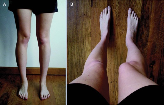
Miserable malalignment syndrome. The patient often presents with medial parapatellar pain with no localizing findings or images indicating pathology: A, when viewed from the front, the squinting patella on the right is well visualized, with both femurs having greater than 50° anteversion; B, what the patient sees looking down her legs. Used with permission.36
Figure 2.
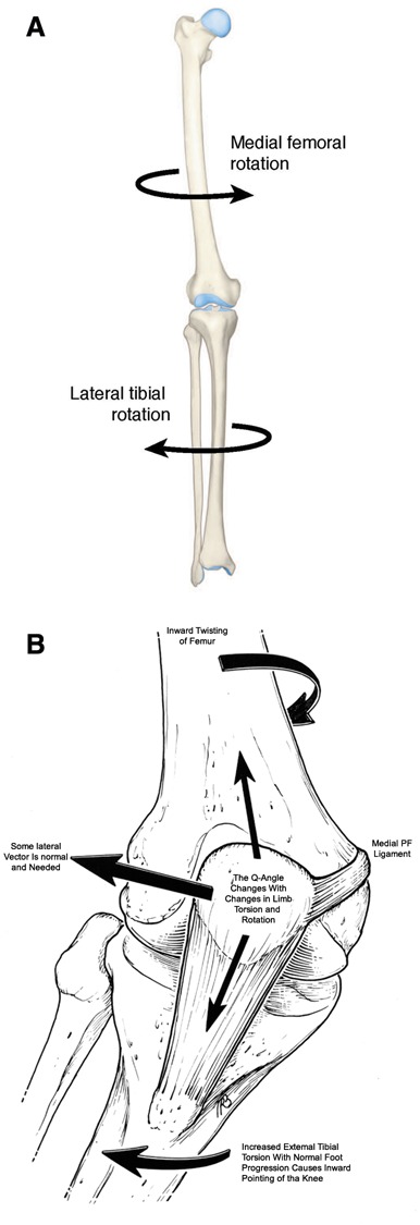
A, overall lower limb alignment shows the inward torsion of the femur attributed to increased femoral anteversion and compensatory tibial rotation. B, the effect of this lower limb alignment, resulting in abnormal patellofemoral loads and tendency for lateral subluxation. Used with permission.
Figure 3.
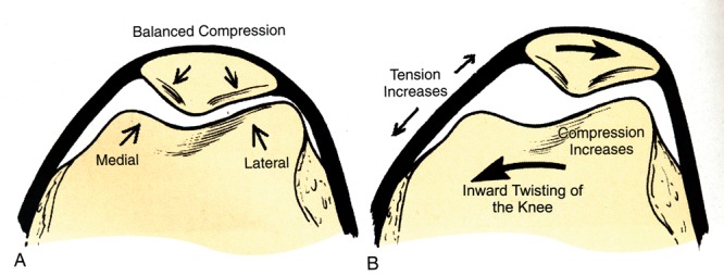
A, when the knee faces forward with normal foot progression, the patellofemoral joint forces are balanced. B, when the knee faces inward with normal foot progression, the medial patellofemoral ligament tension and forces on lateral patellar facet are increased, whereas the forces on medial facet are decreased. Used with permission.36
Several studies have been performed to quantify femoral and patellar shape in patients with patellofemoral pain or instability.13,17,19,29 Similarly, several studies have been performed to assess patellar position and orientation in 2 and 3 dimensions, at a single angle or at sequential angles of knee flexion, using radiographs, computed tomography (CT), and magnetic resonance imaging (MRI) both statically and dynamically.32,46 Relatively few studies, however, have focused on assessment of rotational malalignment of the lower extremities. Compared with frontal-plane and sagittal-plane deformities of the lower limb, which are apparent on clinical examination and conventional radiographs, transverse-plane rotational deformities are often missed or ignored because of difficulties in their assessment.49 Clinical measurements based on physical examination are precise and reliable42,52 but do not quantify the true rotational profile of the hip-knee-ankle axis. Various radiographic techniques involving fluoroscopy,40 axial radiographs,10 and biplane radiography were developed. Dunlap et al,9 Ryder,43 and, later, Magilligan30 reported on radiographic determination of femoral torsion using complex trigonometric formulae based on measured or apparent femoral anteversion angle and femoral neck shaft angle. However, positioning errors and inaccurate location of axes on radiographs were limitations that did not allow for accurate measurements. The gold standard for measurement of lower limb rotational profile has been CT35,54 based on the ability to transpose axial images of hip, knee, and ankle. Other imaging resources—namely, MRI, ultrasound,33 motion analysis,37 and intraoperative navigation6—have been recently recommended with cited advantages36 (Table 1).
Table 1.
Comparison of computed tomography and magnetic resonance imaging for assessment of rotational profile in patellofemoral disorders.
| Computed Tomography | Magnetic Resonance Imaging |
|---|---|
| Radiation hazard due to involvement of ionizing radiation: skin dose, 6.3 mGy; gonadal dose, 2.5 mGy for women and 0.7 mGy for men54 | No ionizing radiation involved |
| Potential errors in children when femoral neck is short and only partially ossified | Ability to visualize nonossified cartilage in joints and growth plates |
| Femoral anteversion measurements based on single or multiple transverse (axial) slices through femoral head, femoral neck, greater trochanter, or femoral shaft | Measurements based on oblique slices parallel to the axis of femoral neck, thus closely approximating the anatomic angle of anteversion44 |
| Less time-consuming | More time-consuming (about 30 minutes), thus potentially necessitating sedation for less cooperative children |
| Less expensive | More expensive |
| Inability to visualize soft tissues or cartilage structures with high resolution | Ability to visualize soft tissues (patellar tendon, retinaculum) and cartilaginous tissues around the knee joint, thus aiding in diagnostic imaging of patellofemoral pathology |
Ultrasound—though inexpensive, noninvasive, and widely available—requires expertise and experience. Its surface landmarks do not always represent the bone’s true axis of rotation, however, and thus may not yield accurate results in the presence of abnormal bone shape; as such, it is not widely used. Motion analysis and intraoperative navigation, though accurate, need significant resources and are not always available for routine clinical diagnostic use. CT and MRI are widely available and used in the clinical setting, familiar to health care professionals, and relatively accurate in measurements. The purpose of the present study is to review the role of CT and MRI in assessment of a lower limb rotational profile.
Anatomic Considerations
Femoral torsion is a twist of the proximal femur relative to the distal femur (Figure 4). Billing3 defined femoral anteversion as the angle between the condylar plane and the plane of anteversion, the latter of which is defined by the long axis of femur and the axis of femoral head (ie, the center of the femoral head and the center of the base of the femoral neck). Billing’s method is not influenced by the shape of the femoral neck, but it does assume that the axis of the femoral neck and femoral shaft intersect. However, this assumption is not true; the femoral neck axis actually passes anterior to the femoral shaft axis by an average of 4.9 mm.51 For assessment of the condylar axis, 4 versions of the tabletop method have been proposed (Figure 5): a tangent through the posterior aspect of femoral condyles (classic tabletop method),35 a line through the widest dimension of the condyles,55 a line through the centroids of medial and lateral condyles,55 and a line bisecting the tangents to the anterior and posterior aspects of femoral condyles.20 The line through the posterior aspect of femoral condyles has been the simplest and most reproducible.35 The posterior condylar axis measures 6° more than the axis through the epicondyles.57 The measurements for condylar axis are made on the distal femoral section with the greatest anteroposterior width.51 Sections through the extreme proximal or distal part of the femoral condyle should not be used to determine the condylar axis, because they tend to underestimate or overestimate femoral anteversion, respectively.35
Figure 4.
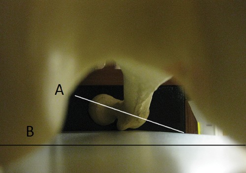
A femur through the intercondylar notch with posterior femoral condyles on a flat surface shows femoral anteversion. Line A (proximal femur) represents the axis of the femoral neck, which is angled anteriorly in relationship to line B (distal femur), representing the tangent to posterior femoral condyles.
Figure 5.
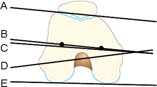
Axes to determine the condylar plane: B, the axes through the centroid of medial and lateral femoral condyle; C, the bisector between tangents A (anterior) and E (posterior); D, the widest diameter through the medial and lateral condyle; E, the tangent through the posterior aspect of the femoral condyles (the most frequently used for determining condylar axes).
On the basis of measurements from 630 dry anatomic femoral specimens, Kingsley and Olmstead27 reported that the mean femoral anteversion angle was 8.0° (range, −20° to 38°), with females having a minor increase in mean anteversion angle compared with males and with right-sided femora having a minor increase compared with left-sided femora. In infants (mean, 24.4°; range, −10° to 64°) and children (mean, 17.2°; range, −4.5° to 38°), the mean femoral anteversion angle was higher. Thus, with growth, the angle of femoral anteversion decreases, which correlates with the clinical picture: Most femoral torsional issues in childhood resolve or are accommodated with age, leaving only a few with functional or cosmetic problems.8 The authors also noted that the head was not centered on the neck of the femur in 68.7% of specimens; thus, the femoral head was not used for calculation of the axis of the femoral neck. Sugano et al51 confirmed this finding and noted that the average distance between the femoral neck axis and femoral head center was 1.3 mm. Yoshioka et al57 measured femoral anteversion and noted an average anteversion of 13.1° using posterior condylar axis and 7.4° when measured across the epicondyles. As a goal for correction, Teitge53 used 13° as an arbitrary value for femoral anteversion.
Tibial torsion is defined as the anatomic twist of the proximal versus distal articular axis of the tibial bone around the longitudinal axis50 (Figure 6). The major part of external tibial torsion is derived from the proximal one-fourth of tibia.22 The angle of external tibial torsion is typically measured between the posterior tibial plateau and the axis of ankle malleoli. When the distal tibia and fibula are both used for measurement of external tibial torsion (tibiofibular torsion), the value is increased as compared with measurements obtained by using tibia alone (tibial torsion), and it represents true ankle mortise alignment.22 The external tibial torsion is always greater than the angle of femoral anteversion. Lerat et al29 described the relationship between the angles for external tibial torsion and femoral anteversion, noting that the larger the difference, the more the correlation with patellofemoral pathology. When the knee is in extension, the tibia is externally rotated in relation to the femur. Hyperextension of 15°, as in a ligamentously lax individual, is associated with a 13° increase in femorotibial rotation and increased varus.29 This relationship emphasizes the important role of rotational alignment on the sagittal and frontal plane alignment.
Figure 6.
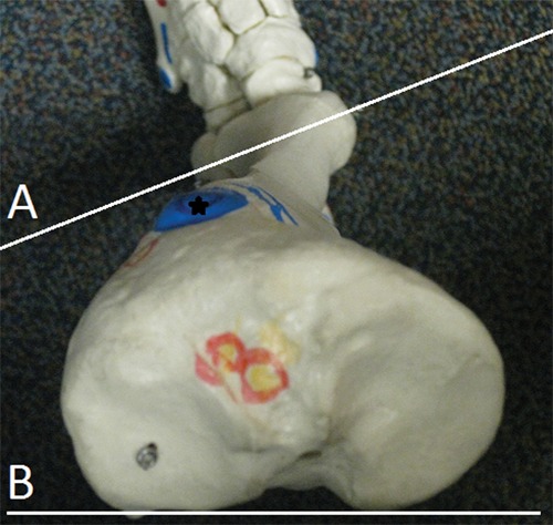
Tibia from top shows tibial torsion. Line A (distal tibia) is externally rotated in relationship to line B (proximal tibia), representing the twist in tibia. The position of tibial tubercle (star) shows that majority of the twist occurs in the proximal tibia.
Clinical Measurement of Lower Limb Rotational Profile
On the basis of the clinical examination in prone position, Staheli49 established age- and sex-related values for rotational profile. The following values were measured in 1000 normal limbs: foot progression angle (mean, 10° external; range, −3° to 20°), medial rotation of hip for males (mean, 50°; range, 25° to 65°), medial rotation of hip for females (mean, 40°; range, 15° to 60°), lateral rotation of hip (mean, 45°; range, 25° to 65°), thigh-foot angle (mean, 10° outward; range, −5° to 30°), and angle of transmalleolar axis (mean, 20°; range, 0° to 45°). The severity of femoral torsion was graded as mild (medial hip rotation, 70° to 80°; lateral hip rotation, 10° to 20°), moderate (medial hip rotation, 80° to 90°; lateral hip rotation, 0° to 10°), or severe (medial hip rotation > 90°, lateral hip rotation ≤ 0°)49 (Figure 7). Patients with medial hip rotation > 85° and lateral rotation < 10° were considered to be candidates for surgical intervention.48 Tibial torsion assessment was based on the angle of the transmalleolar axis. Deformity assessment of the hind foot was based on the difference between the angle of the transmalleolar axis and the thigh-foot angle. Combined deformity of the tibia and hind foot was assessed using thigh-foot angle. External tibial torsion > 30° and internal tibial torsion > 15° based on thigh-foot angle measurements may need surgical correction.48
Figure 7.
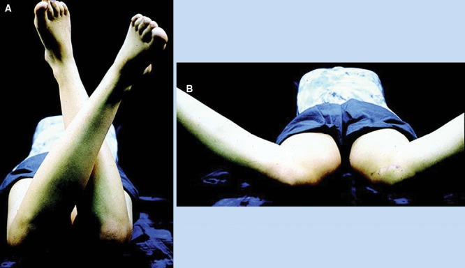
Decreased external rotation (A) and increased internal rotation (B) suggests femoral anteversion. Used with permission.36
Other clinical methods for determination of lower limb rotational profile have been described. With the patient in a prone position, the greater trochanter is palpated in its most lateral position, which reflects a horizontal femoral neck axis. With the knee bent to 90°, the angle between the longitudinal axis of the leg and a vertical line represents femoral torsion.42 Tamari52 recommended a modification of this method using Nelaton’s line (ie, connecting the anterior superior iliac spine and the ischial tuberosity). However, there were significant differences between the clinical methods and true femoral torsion. Wynne-Davies56 described a clinical method for measurement of tibial torsion as an angle between the posterior surface of tibia (with the tibial tuberosity facing anterior) and the angle of the transmalleolar axis. Again, significant differences were found between the clinical methods and true measurements of tibial torsion. Jakob22 described a simple clinical method by measuring the angle between the second metatarsal and the tibial tuberosity, with the patient sitting on the edge of the bed. Another method is to turn the plantigrade foot into maximum internal and external rotation; the mean of these 2 angles is equivalent to the tibial torsion.22 The lack of clinical method accuracy in determining the true rotational profile of the lower limb is due to errors in positioning, variability of surface landmarks, anatomic variations among individuals,52 and the subjective nature of the technique.47 Recent gait analysis showed a considerable influence of dynamic compensation, especially in the hip, which should be considered in evaluation of the rotational profile.38 Although differences exist between the clinical methods and the true rotational alignment of lower limbs, there has been good correlation between these measurements. Hence, clinical methods—though not suitable to quantify rotational malalignment—should be utilized for screening and descriptive purposes.
CT Assessment of Rotational Profile
Since the advent of the CT scan in 1972, many clinical studies have used CT to determine the relationship of femoral torsion to patellofemoral pathology. Eckhoff et al11,12 found a significant difference in femoral anteversion in 20 patients with anterior knee pain (23° ± 12°) compared with asymptomatic controls (18° ± 7°). Dejour et al7 found that femoral anteversion was 10.8° ± 8.7° in controls, compared with 15.6° ± 9° in patients with objective patellar instability; the authors described femoral anteversion as a “favorable environment” for patellar instability. Lee et al28 demonstrated in a cadaveric study that lateral patellar facet contact pressure increased with femoral anteversion.
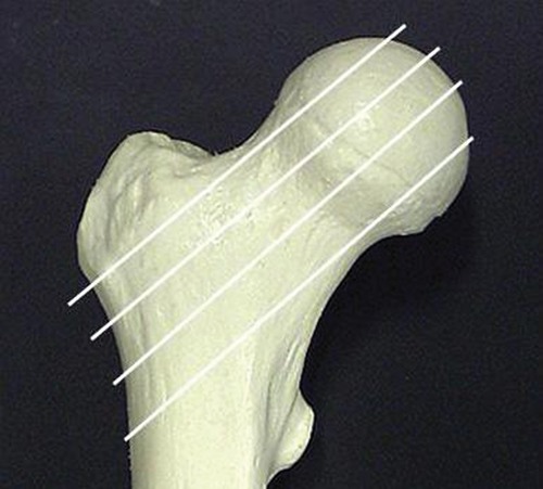
CT methods for measurement of femoral anteversion differ with regard to anatomic landmarks and positioning of the axes and have hence provided different values. Weiner et al55 and Hernandez et al20 described the angle of anteversion as an angle between the condylar axis and an approximation of the axis of the femoral neck (determined on a single image made along the femoral neck). Transverse CT scans, however, pass through the femoral neck obliquely, and from these images, the true axis of the femoral neck may be difficult to define or may be inaccurate, unless the femoral neck is perfectly cylindrical or the neck-shaft angle is 90 degrees. The shape of the femoral neck is elliptical and the long axis rotates from a relatively anterior proximal position to a relatively posterior distal position. Hence, the accuracy of a single transverse section is significantly affected by its level on the femoral neck (Figure 8).51 Anteversion is underestimated by more proximal sections and overestimated by more distal sections. With the Weiner method,55 the angle of anteversion was consistently underestimated by an average of 10° compared with direct measurements and reproducible to within only 3.6°.35 To circumvent this issue, Reikeras et al39 used superimposition of 2 transverse images through the proximal part of the femoral neck to determine the plane of anteversion: 1 through the center of the femoral head and 1 through the middle of the narrowest diameter of the femoral neck (Figure 9). This method typically underestimates the femoral anteversion measurements.51 Murphy et al35 further modified this technique by selecting the center of the femoral head and the centroid of the femoral diaphysis on transverse section through the base of the femoral neck (greater trochanteric level) as end points for determination of femoral neck axis (Figure 8). This is also referred to as the head-trochanter axis.18 Given that the greater trochanter is relatively posterior compared with the femoral neck and the neck axis passes anterior to the shaft axis, this method usually overestimates femoral anteversion measurements.51 Sugano et al,51 with a 3-dimensional reconstruction model for measurement of femoral anteversion, found that none of the methods based on transverse CT sections without reconstruction were capable of predicting anteversion within 10° of anatomic measurement with 95% confidence. In their study, the transverse section through the most proximal portion of the inferior neck (without the head included) provided the most accurate estimate of femoral neck axis.
Figure 8.
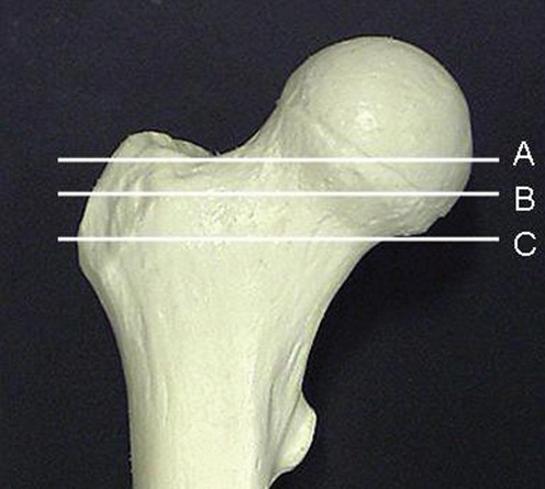
Single transverse sections at various levels have been used for determination of femoral anteversion axes. Section B, as described by Weiner et al,55 passes through femoral head and neck but underestimates the true anteversion. Section C, as described by Sugano et al,51 passes just inferior to the femoral head and approximates the true anteversion measurements. The more proximal the section (ie, section A), the greater the underestimation of femoral anteversion.
Figure 9.
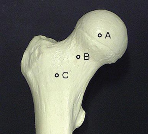
Superimposition of transverse images through different levels for determination of femoral anteversion axes. Section through the center of femoral head (A) and femoral neck (B), as described by Reikeras et al,39 underestimates the femoral anteversion measurements. Section through the center of femoral head (A) and base of the neck (C), as described by Murphy, overestimates the true anteversion measurements.
Another use of 3-dimensional reconstruction of the CT scan is in presence of femoral head deformity or valgus neck or where proper positioning is difficult to achieve.26 A recent technique of axial oblique reformations parallel to the long axis of the femoral neck based on axial CT slices allowed for more accurate anteversion assessment independent of patient positioning.24 Based on postprocessing software, this technique of axial oblique reformatting parallel to the femoral neck is similar to the MRI technique44,54 (Figure 10).
Figure 10.
Axial (oblique) images through the femoral neck give the most accurate estimate of femoral anteversion. With the patient in supine position, with symmetric positioning of both lower extremities, and with hips and knees in extension, a coronal-section scout view of pelvis and femur is obtained, parallel to the table. Oblique axial-to-sagittal sections can then be placed parallel to the femoral neck axis, exactly perpendicular to the table. The femoral neck anteversion is determined on the single image, which shows the center of the femoral head and femoral neck.
Tibial torsion is defined as the anatomic twist of the proximal versus distal articular axis of the tibial bone around the longitudinal axis50 (Figure 2). In a cadaveric study using 3-dimensional CT, Eckhoff and Johnson11 described the determinants for proximal tibial axes. They concluded that within 2 cm of the articular surface, the level of the proximal tibial axis had no effect on the tibial torsion measurement. Similarly, the slope of the proximal tibial cut, with respect to the long tibial axis, had no effect on the tibial torsion measurement. They concluded that there was no significant difference in tibial torsion measured by reference to the posterior-condylar axis instead of the transtibial axis in cuts below the articular surface.
Rosen and Sandick41 recommended a section through the upper end of the tibia and fibula for determination of proximal tibial axes. The reference line was between the junction of the anterior and lateral aspect of the fibular head and the most prominent point of the medial condyle; this line deviated from the transcondylar axis by 13° of external torsion.41 For distal tibial measurements, the section is obtained at the most distal part of the tibia, just above the ankle joint.38,45 Rosen and Sandick41 described the distal tibiofibular axes as a line between the junction of the lateral and posterior borders of the fibula and the junction of the anterior and medial borders of the tibia. This line deviates from the transmalleolar axis by 13° of external torsion. Eckhoff and Johnson11 recommended the use of the bimalleolar (transmalleolar) axis at the distal tibia, defined by the line joining the center of the malleoli.
MRI Assessment of Rotational Profile
Galbraith et al16 and Bauman et al1 initially described MRI measurements for femoral anteversion using transverse sections analogous to those of CT. Guenther et al18 first described the ability of MRI to alter the image plane parallel to the femoral neck, giving MRI an advantage over CT axial views. By the image plane being oriented parallel to the femoral neck, visualization of the femoral neck axis is improved. Using T1-weighted gradient echo sequence of MRI, Schneider et al44 measured femoral anteversion and tibial torsion in healthy adult volunteers using transverse sections through the proximal femur analogous to those of CT and then compared sections along the axis of the neck of femur. For the distal femur, the tangent to the dorsal border of femoral condyles was taken as the line of reference. The angle of anteversion based on an inclined line of axis parallel to the femoral neck (16.7° ± 6.3°) was significantly higher than that based on a CT-analogous single transverse section (11.2° ± 5.4°).
For measurement of tibial torsion, Schneider et al chose the section of proximal tibia immediately below the knee joint line and proximal to the fibular head. The line of reference from this section was the tangent to the dorsal border of the tibia. In the distal tibia, the section immediately proximal to the talocrural (ankle) joint line was chosen. The distal line of reference was formed by joining the center of a circle fitted to the distal tibia with the midpoint of a line across the fibular notch of tibia.44 Tamari et al52 measured true tibiofibular torsion (in contrast to tibial torsion) by defining the distal reference line joining the center of the circle fitted to the distal part of tibia with the most prominent point of the lateral malleolus.
Knee Torsion and Submalleolar Torsion
Tibial torsion could be due to rotation of the leg in relation to the thigh at the knee joint (knee torsion), to twisting within the leg itself (true tibial torsion), or to rotation of the ankle in relation to the leg at the ankle joint (submalleolar torsion).41 Knee torsion is measured by superimposition of a line along the posterior cortex of the proximal tibia section on the posterior condylar axes on the distal femur section. The angle between these 2 lines is the measurement for knee torsion. The angle of submalleolar torsion is measured between the transmalleolar axis and the foot axis.29 During assessment of malalignment, submalleolar torsion must be taken into account.
Tibial Tubercle–Trochlear Groove Distance
The anatomic relationship between the femoral trochlear groove and the anterior tibial tubercle can be measured by superimposition of axial CT images25,34 or MRI.31 This measurement of tibial tubercle lateralization is more precise than the clinical measurement of the Q angle. A laterally subluxed patella can falsely decrease the value of the Q angle but may not alter the tibial tubercle–trochlear groove distance. Various studies have determined the relationship between patellofemoral pain, instability, and tibial tubercle–trochlear groove distance.25,34 Using CT scan, Dejour et al7 reported a mean lateral tibial tubercle offset distance of 19.8 ± 1.6 mm in patients with patellar instability and 12.7 ± 3.4 mm in controls. Given these results, they defined 20 mm of offset as the pathologic threshold. Beaconsfield et al2 used CT to determine the average distance between the tibial tuberosity and the trochlear groove: 13 mm, with suggested surgical correction for a distance > 20 mm. Galland et al17 studied CT scans of 120 normal knees and compared them to 900 knees with a variety of patellofemoral pathology. A trochlear groove–tibial tubercle distance of 12 mm or less was normal. Greater than 16 mm was indicative of malalignment; however, the distribution and statistical analysis were not reported. Jones et al25 studied patients with anterior knee pain in 20° of knee flexion using CT scan and reported an average offset distance of 12.2 ± 0.5 mm in patients with patellar malalignment versus 6.4 ± 0.4 mm in controls. The discrepancy in threshold values could be due to orientation and position of the lower limb, CT parameters, measurement landmarks on the tibia, knee flexion, and tibial rotation degrees. McNally et al31 studied patellar subluxation using dynamic and static MRI. They proposed a grading system to categorize patellar maltracking (mild < 5 mm lateral subluxation or tilt only; moderate to severe > 1 cm lateral subluxation). The mean tibial tuberosity offset distance was 17 ± 2.4 mm for mild subluxation, 17.4 ± 3.3 mm for moderate, and 21.5 ± 3.4 mm for severe. MRI better delineates the soft tissue borders required to measure the patellar tendon insertion site on the tibial tubercle.
Lerat et al29 described the effect of knee hyperextension on tibial tubercle–trochlear groove distance. In a ligamentously lax or deficient patient, hyperextension of 15° is associated with increased femorotibial rotation and an increase of 7 mm in tibial tubercle–trochlear groove distance. The center of the patellar tendon may not always coincide with the anatomic center of the osseous tibial tubercle. MRI does provide a more accurate determination of the center of the tendinous attachment. With increased tibial tubercle–trochlear groove distance, the rotational alignment of the femur and tibia is important because surgical correction of the rotational malalignment may be required, as opposed to tibial tubercle transfer.
Preferred Technique
Knees should be imaged in a 1.5-T, 64-MHz magnetic resonance imager with a transmit/receive extremity coil. T1-weighted spin echo axial-plane imaging of the hip, knee, and ankle is performed with the following variables: repetition time, 250 to 500 milliseconds; echo time, minimum; number of excitations, 2; matrix, 256 × 192 and 256 × 256; field of view, 30 to 38 cm; section thickness, 3 mm; intersection gap, 0.6 to 1.5 mm; number of sections, 8 to 10. Sagittal T1-weighted magnetic resonance images of the knee are also obtained (repetition time, 500; echo time, low).
Patients are supine with hips and knees in relative extension. The feet are placed in a specially designed foot fixture to simulate the foot progression angle during normal gait. No quadriceps contraction occurs during the examination. A coronal scout image of the hip is taken and oblique cuts parallel to the femoral neck are made, as described by Tomczak54 (Figure 11A). Next, an axial scout image at midpatellar level is taken, and sagittal cuts are made through the medial aspect of both knees. The most proximal aspect of the medial femoral condyle is identified for each knee, and an axial cut is made at this level, parallel to the tibial plateau (Figure 11B). The anteroposterior thickness of the femur is measured along this line and used as the standard distance reference for the rest of the knee evaluation. A second axial cut is made through the distal femur at a distance of 50% of the standard distance reference, distal to the first cut. The tibial measurements include an axial cut parallel to the tibial plateau at the most proximal insertion of the patellar tendon. Additional distal axial cuts are made at a distance of 10% and 20% of the standard distance reference from the first tibial cut. Another axial cut is made parallel to the tibial plateau, 1 cm below the joint line (Figure 11B). A scout coronal image of the ankle joint is taken, and 3 axial cuts are made through the talus (Figure 11C). These images and MRI parameters were selected to optimize and standardize image quality; ensure uniformity in ordering, reading, and measuring protocols; and keep the data acquisition time to the minimum.
Figure 11.

Scout MRI views showing the level and axis of sections performed for assessment of femoral neck axis (A), distal femoral and proximal tibial axis (B), and talar axis (C). Used with permission.
A transverse reference line is drawn on each image for accurate transposition of images. Femoral anteversion is determined on MRI with the method described by Tomczak54 (Figure 12). With this line, the image is transposed over the image of distal femur; the posterior condylar axis is drawn as a tangent off the posterior femoral condyles (Figure 13). The angle between these 2 lines is the angle of femoral anteversion. If positive, the angles are added; if negative, subtracted. Knee torsion is measured by drawing a line along the posterior cortex of the tibia on the axial image through the proximal tibia (Figure 14). This image is transposed over the image of the distal femur, with the posterior condylar axis marked. The angle between these 2 lines is the knee torsion. Tibial torsion is measured by drawing a line along the anterior surface of the talus on the axial image through the talus (Figure 15). This image is superimposed on the film from the proximal tibia; the angle between the anterior talus line and the posterior tibial line is the angle of tibial torsion.
Figure 12.
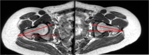
Femoral neck axis is drawn on the section through the center of femoral head and femoral neck, and its angle with a transverse axis is measured.
Figure 13.
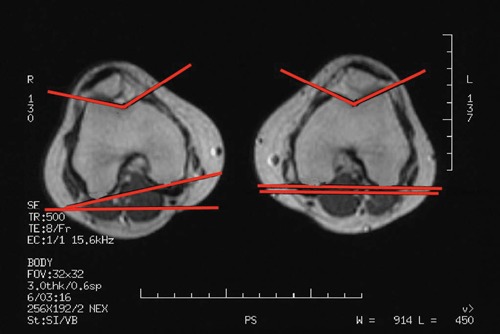
The proximal tibial axis is determined by a tangent to the posterior aspect of the proximal tibia, just below the articular surface and above the level of fibula. Used with permission.
Figure 14.
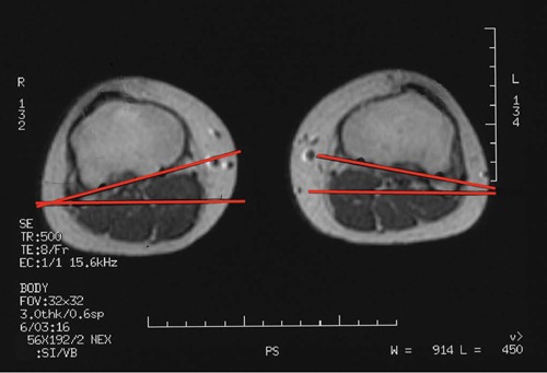
The proximal tibial axis is determined by a tangent to the posterior aspect of the proximal tibia, just below the articular surface and above the level of fibula. Used with permission.
Figure 15.
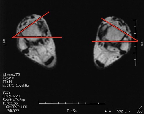
The tangent to the anterior surface of the talus determines the distal axis for tibial torsion measurement. Used with permission.
The posterior condylar axis is determined by a tangent to the posterior aspect of the medial and lateral femoral condyles.
Tibial tubercle offset is measured with the tibial tubercle–trochlear groove distance—the transverse distance from the deepest point of the trochlear groove to the center of patellar tendon insertion. The axial image through the most superior point of insertion of patellar tendon is identified (Figure 16). The width of the patellar tendon is measured along its posterior border and its center point marked. The deepest point of the trochlea on the distal femoral axial image is then transposed, and the transverse distance between the deepest point of the trochlea and the center of patellar tendon is measured parallel to the posterior cortex of the tibia; this distance is the tibial tubercle–trochlear groove distance. The real tibial tubercle–trochlear groove distance is calculated with the measurement scale on the MRI.
Figure 16.
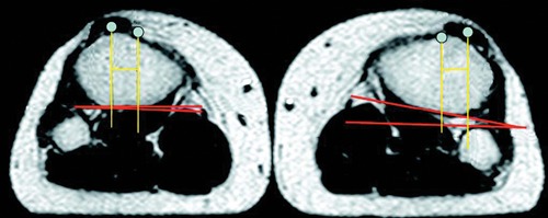
Measurement of tibial tubercle–trochlear groove distance. The section is through the insertion site of patellar tendon. Used with permission.
Conclusion
CT scan and MRI are both used for assessment of the rotational profile of the femur and tibia during evaluation for patellofemoral disorders. The axial oblique images parallel to the femoral neck most closely approximate true femoral anteversion. MRI appears to be superior to CT scan, given that oblique images of the femoral neck can be obtained and that ionizing radiation can be avoided. A standardized protocol defining the level and axes for measurement of rotational alignment should be used to maintain consistency in measurements in clinical practice.
Footnotes
No potential conflict of interest declared.
References
- 1. Bauman PA, Singson R, Hamilton WG. Femoral neck anteversion in ballerinas. Clin Orthop. 1994;302:57-63 [PubMed] [Google Scholar]
- 2. Beaconsfield T, Pintore E, Maffulli N, Petri GJ. Radiological measurements in patellofemoral disorders: a review. Clin Orthop. 1994;308:18-28 [PubMed] [Google Scholar]
- 3. Billing L. Roentgen examination of the proximal femur end in children and adolescents: a standardized technique also suitable for determination of the collum, anteversion and epiphyseal angles. A study of slipped epiphysis and coxa plana. Acta Radiol. 1954;110(suppl):1. [PubMed] [Google Scholar]
- 4. Bruce WD, Stevens PM. Surgical correction of miserable malalignment syndrome. J Pediatr Orthop. 2004;24(4):1-5 [DOI] [PubMed] [Google Scholar]
- 5. Chung CY, Lee KM, Park S, et al. Validity and reliability of measuring femoral anteversion and neck-shaft angle in patients with cerebral palsy. J Bone Joint Surg Am. 2010;92:1195-1205 [DOI] [PubMed] [Google Scholar]
- 6. Citak M, Gardner MJ, Citak M, et al. Navigated femoral anteversion measurements: a new intraoperative technique. Injury. 2008;39:467-471 [DOI] [PubMed] [Google Scholar]
- 7. Dejour H, Walch G, Nove-Josserand L, Guier C. Factors of patellar instability: an anatomic radiographic study. Knee Surg Sports Traumatol Arthrosc. 1994;2(1):19-26 [DOI] [PubMed] [Google Scholar]
- 8. Delgado ED, Schoenecker PL, Rich MM, Capelli AM. Treatment of severe torsional malalignment syndrome. J Pediatr Orthop. 1996;16:484-488 [DOI] [PubMed] [Google Scholar]
- 9. Dunlap K, Shands AR, Jr, Hollister LC, Jr, Gaul JS, Jr, Streit HA. A new method for determination of torsion of the femur. J Bone Joint Surg Am. 1953;35:289-311 [PubMed] [Google Scholar]
- 10. Dunn DM, Notley B. Anteversion of the neck of the femur: a method of measurement. J Bone Joint Surg Br. 1952;34:181-186 [DOI] [PubMed] [Google Scholar]
- 11. Eckhoff DG, Johnson KK. Three-dimensional computed tomography reconstruction of tibial torsion. Clin Orthop. 1994;302:42-46 [PubMed] [Google Scholar]
- 12. Eckhoff DG, Montgomery WK, Kilcoyne RF, Stamm ER. Femoral morphometry and anterior knee pain. Clin Orthop. 1994;302:69-74 [PubMed] [Google Scholar]
- 13. Elias DA, White LM. Imaging of patellofemoral disorders. Clin Radiol. 2004;59:543-557 [DOI] [PubMed] [Google Scholar]
- 14. Fabry G, MacEwen GD, Shands AR., Jr Torsion of the femur: a follow-up study in normal and abnormal conditions. J Bone Joint Surg Am. 1973;55(8):1726-1738 [PubMed] [Google Scholar]
- 15. Flandry F, Hughston JC. Complications of extensor mechanism surgery for patellar malalignment. Am J Orthop. 1995;24:534-543 [PubMed] [Google Scholar]
- 16. Galbraith RT, Gelberman RH, Hajek PC, et al. Obesity and decreased femoral anteversion in adolescence. J Orthop Res. 1987;5:523-528 [DOI] [PubMed] [Google Scholar]
- 17. Galland O, Walch G, Dejour H, Carret JP. An anatomical and radiological study of the femoropatellar articulation. Surg Radiol Anat. 1990;12:119-125 [DOI] [PubMed] [Google Scholar]
- 18. Guenther KP, Tomczak R, Kessler S, et al. Measurement of femoral anteversion by magnetic resonance imaging: evaluation of a new technique in children and adolescents. Eur J Radiol. 1995;21:47-52 [DOI] [PubMed] [Google Scholar]
- 19. Harbaugh CM, Wilson NA, Sheehan FT. Correlating femoral shape with patellar kinematics in patients with patellofemoral pain. J Orthop Res. 2010;28:865-872 [DOI] [PMC free article] [PubMed] [Google Scholar]
- 20. Hernanadez RJ, Tachdjian MO, Poznanski AK, Dias LS. CT determination of femoral torsion. AJR Am J Roentgenol. 1981;137:97-101 [DOI] [PubMed] [Google Scholar]
- 21. Hughston JC. Subluxation of the patella. J Bone Joint Surg Am. 1968;50:1003-1026 [PubMed] [Google Scholar]
- 22. Jakob RP, Haertel M, Stussi F. Tibial torsion calculated by computerized tomography and compared to other methods of measurement. J Bone Joint Surg Br. 1980;62B:238-242 [DOI] [PubMed] [Google Scholar]
- 23. James SL. Chondromalacia of the patella in the adolescent. In: Kennedy JC, ed. The Injured Adolescent Knee. Baltimore, MD: Williams & Wilkins Co; 1979:205-251 [Google Scholar]
- 24. Jarrett DY, Oliveria AM, Zou KH, Snyder BD, Kleinman PK. Axial oblique CT to assess femoral anteversion. AJR Am J Roentgenol. 2010;194:1230-1233 [DOI] [PubMed] [Google Scholar]
- 25. Jones RB, Barlett EC, Vainright JR, Carroll RG. CT determination of tibial tubercle lateralization in patients presenting with anterior knee pain. Skeletal Radiol. 1995;24:505-509 [DOI] [PubMed] [Google Scholar]
- 26. Kim JS, Park TS, Park SB, et al. Measurement of femoral neck anteversion in 3D: part 1. 3D imaging method. Med Biol Eng Comput. 2000;38:603-609 [DOI] [PubMed] [Google Scholar]
- 27. Kingsley PC, Olmsted KL. A study to determine the angle of anteversion of the neck of the femur. J Bone Joint Surg Am. 1948;30:745-751 [PubMed] [Google Scholar]
- 28. Lee TQ, Anzel SH, Bennett KA, Pang D, Kim WC. The influence of fixed rotational deformities of the femur on the patellofemoral contact pressures in human cadaver knees. Clin Orthop. 1994;302:69-74 [PubMed] [Google Scholar]
- 29. Lerat JL, Moyen B, Bochu M, Galland O. Femoropatellar pathology and rotational or torsional abnormalities of the inferior limb: the use of CT scan. In: Muller W, Hackenbruch W, eds. Surgery and Arthroscopy of the Knee: Second Congress of the European Society. Berlin, Germany: Springer-Verlag; 1988 [Google Scholar]
- 30. Magilligan DJ. Calculation of the angle of anteversion by means of horizontal lateral roentgenography. J Bone Joint Surg Am. 1956;38:1231-1246 [PubMed] [Google Scholar]
- 31. McNally EG, Ostlere SJ, Pal C, Phillips A, Reid H, Dodd C. Assessment of patellar maltracking using combined static and dynamic MRI. Eur Radiol. 2000;10:1051-1055 [DOI] [PubMed] [Google Scholar]
- 32. McWalter EJ, MacIntyre NJ, Cibere J, Wilson DR. A single measure of patellar kinematics is an inadequate surrogate marker for patterns of three-dimensional kinematics in healthy knees. Knee. 2010;17:135-140 [DOI] [PubMed] [Google Scholar]
- 33. Moulton A, Upadhyay SS. A direct method of measuring femoral anteversion using ultrasound. J Bone Joint Surg Br. 1982;64:469-472 [DOI] [PubMed] [Google Scholar]
- 34. Muneta T, Yamamoto H, Ishibashi T, Asahina S, Furuya K. Computerized tomographic analysis of tibial tubercle position in the painful female patellofemoral joint. Am J Sports Med. 1994;22:67-71 [DOI] [PubMed] [Google Scholar]
- 35. Murphy SB, Simon SR, Kijewski PK, Wilkinson RH, Griscom NT. Femoral anteversion. J Bone Joint Surg. 1987;69:1169-1176 [PubMed] [Google Scholar]
- 36. Noyes FR, Barber-Westin SD. Operative options for extensor mechanism malalignment and patellar dislocation. In: Noyes FR, Barber-Westin SD, eds. Noyes Knee Disorders: Surgery, Rehabilitation and Clinical Outcomes. Philadelphia, PA: Elsevier; 2009:995-1025 [Google Scholar]
- 37. Paulos L, Swanson SC, Stoddard GJ, Barber-Westin SD. Surgical correction of limb malalignment for instability of the patella: a comparison of 2 techniques. Am J Sports Med. 2009;37(7):1288-1300 [DOI] [PubMed] [Google Scholar]
- 38. Radler C, Kranzl A, Manner HM, et al. Torsional profile versus gait analysis: consistency between the anatomic torsion and the resulting gait pattern in patients with rotational malalignment of the lower extremity. Gait Posture. 2010;32:405-410 [DOI] [PubMed] [Google Scholar]
- 39. Reikeras O, Bjerkreim I, Kolbenstvedt A. Anteversion of the acetabulum and femoral neck in normals and in patients with osteoarthritis of the hip. Acta Orthop Scand. 1983;54:18-23 [DOI] [PubMed] [Google Scholar]
- 40. Rogers SP. A method for determining the angle of torsion of the neck of the femur. J Bone Joint Surg. 1931;13:821-824 [Google Scholar]
- 41. Rosen H, Sandick H. The measurement of tibiofibular torsion. J Bone Joint Surg. 1955;37:847-855 [PubMed] [Google Scholar]
- 42. Ruwe PA, Gage JR, Ozonoff MB, DeLuca PA. Clinical determination of femoral anteversion: a comparison with established techniques. J Bone Joint Surg Am. 1992;74:820-830 [PubMed] [Google Scholar]
- 43. Ryder CT, Crane L. Measuring femoral anteversion: the problem and a method. J Bone Joint Surg Am. 1953;35:321-328 [PubMed] [Google Scholar]
- 44. Schneider B, Laubenberger J, Jemlich S, et al. Measurement of femoral antetorsion and tibial torsion by magnetic resonance imaging. Br J Radiol. 1997;70:575-579 [DOI] [PubMed] [Google Scholar]
- 45. Seber S, Hazer B, Kose N, Gokturk E, Gunal I, Turgut A. Rotational profile of the lower extremity and foot progression angle: computerized tomographic examination of 50 male adults. Arch Orthop Trauma Surg. 2000;120:255-258 [DOI] [PubMed] [Google Scholar]
- 46. Shin CS, Carpenter RD, Majumdar S, Ma CB. Three-dimensional in vivo patellofemoral kinematics and contact area of anterior cruciate ligament-deficient and reconstructed subjects using magnetic resonance imaging. Arthroscopy. 2009;25(11):1214-1223 [DOI] [PubMed] [Google Scholar]
- 47. Souza RB, Powers CM. Concurrent criterion-related validity and reliability of a clinical test to measure femoral anteversion. J Orthop Sports Phys Ther. 2009;39(8):586-592 [DOI] [PubMed] [Google Scholar]
- 48. Staheli LT. Torsion: treatment indications. Clin Orthop. 1989;247:61-69 [PubMed] [Google Scholar]
- 49. Staheli LT, Corbett M, Wyss C. Lower extremity rotational problems in children: normal values to guide management. J Bone Joint Surg Am. 1985;67:39. [PubMed] [Google Scholar]
- 50. Stuberg W, Temme J, Kaplan P, Clarke A, Fuchs R. Measurement of tibial torsion and thigh-foot angle using goniometry and computed tomography. Clin Orthop. 1991;272:208-212 [PubMed] [Google Scholar]
- 51. Sugano N, Noble PC, Kamaric E. A comparison of alternative methods of measuring femoral anteversion. J Comput Assist Tomogr. 1998;22:610-614 [DOI] [PubMed] [Google Scholar]
- 52. Tamari K, Tinley P, Briffa K, Breidahl W. Validity and reliability of existing and modified clinical methods of measuring femoral and tibiofibular torsion in healthy subjects: use of different reference axes may improve reliability. Clin Anat. 2005;18:46-55 [DOI] [PubMed] [Google Scholar]
- 53. Teitge RA. Patellofemoral disorders: correction of rotational malalignment of the lower extremity. In: Noyes Knee Disorders: Surgery, Rehabilitation and Clinical Outcomes. Philadelphia, PA: Elsevier; 2009:1026-1049 [Google Scholar]
- 54. Tomczak RJ, Guenther KP, Rieber A, et al. MR Imaging measurement of the femoral antetorsional angle as a new technique: comparison with CT in children and adults. AJR Am J Roentgenol. 1997;168:791-794 [DOI] [PubMed] [Google Scholar]
- 55. Weiner DS, Cook AJ, Hoyt WA, Jr, Oravec CE. Computed tomography in the measurement of femoral anteversion. Orthopedics. 1978;1(4):299-306 [PubMed] [Google Scholar]
- 56. Wynne-Davies R. Talipes equinovarus: a review of eighty-four cases after completion of treatment. J Bone Joint Surg Br. 1964;46:464-476 [PubMed] [Google Scholar]
- 57. Yoshioka Y, Cooke DV. Femoral anteversion: assessment based on function axes. J Orthop Res. 1987;5:86-91 [DOI] [PubMed] [Google Scholar]


