Abstract
A carbon nanotube (CNT) can be toxic to a living cell by binding to proteins and then impairing their functionalities; however, an efficient screening method that examines binding capability of a CNT to protein molecules in vitro is still unavailable. Here, we show that a nanopore-based sensor can be used to investigate CNT-protein interactions. With proof-of-principle molecular dynamics simulations, we have measured ionic currents in a nanopore when threading a CNT-protein complex through the pore, and demonstrated that CNT’s binding capability, and thus potential nanotoxicity, can be inferred from current signals. We have then further investigated mechanics and energetics of CNT-protein interactions with the nanopore sensor. These findings indicate that solid-state nanopores have the potential to be ultra-sensitive and high-throughput sensors for nanotoxicity.
Keywords: Carbon nanotubes, nanopores, nanotoxicity, electrophoresis, proteins
Accompanied with fast-paced developments and applications of carbon-based nanomaterials, such as carbon nanotubes (CNTs), growing concerns of bio-safety of these nanomaterials to a human body have led to strategic research of nanotoxicity1. It has been found experimentally that a CNT can pass a cell membrane and subsequently enter cytoplasm and nucleus2, causing cell mortality. At a molecular level, the nanotoxicity can result from strong interactions between a CNT and a protein molecule, such as an insertion of a CNT into the ligand-binding site of a protein molecule3,4. Consequently, a malfunction of the affected protein molecule occurs in cell metabolism. With current state-of-art experimental approaches, studying interactions of a CNT-protein complex is still challenging. Therefore, developing a new ultra-sensitive and high-throughput sensor could greatly accelerate studies in this field.
As a promising new sensor, a nanopore5 in a biological or solid-state membrane provides a confined geometry that is ideal for detecting a biological molecule. When a biomolecule is electrophoretically driven through a nanopore, an ionic current through the pore is temporarily reduced. From signals of current blockade, physical features of a transported molecule can be inferred and quantified. Besides the high sensitivity, another advantage of nanopore-based sensors is their intrinsic characteristics of high-throughput sensing6,7. As a result, nanopores have been used as ultrasensitive biosensors for single biological molecules, such as DNA6, microRNA8 and proteins9. Potentially, nanopore sensors can be employed to sequence DNA5,10, and even to detect cancer11.
Recently, it was demonstrated experimentally that charged CNTs (modified by DNA) can be electrically driven through a nanopore12. Alternatively, the surface of a CNT can be selectively functionalized with charged carboxyl groups13, which also enables electrophoresis of CNTs in an electric field. In this paper, we studied the electrophoretic motion of a CNT-protein complex in a nanopore and investigated how the nanopore can be used to detect the binding capability (and thus potential nanotoxicity) of a CNT to its bound protein molecule. Using molecular dynamics (MD) simulations, we explored ionic signals during the translocation of a CNT-protein complex in a 3-nm nanopore and obtained binding affinity of the complex from a rupture process in the pore.
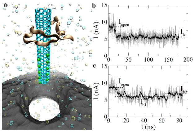
We performed all-atom MD simulations using NAMD14 on the IBM Bluegene Supercomputer. A typical simulation system is illustrated in Fig. 1a. The 30-Å-in-thickness membrane that separates cis. and trans. fluidic chambers was made of an amorphous SiO2 solid. A nanopore drilled through the membrane has an hour-glass shape, with a pore “neck” 15 Å in radius (3-nm nanopore) and pore openings 25 Å in radius. A 1M KCl electrolyte was used on both cis. and trans. sides. We adopted the atomic structure of the protein-CNT complex previously studied for CNT’s toxicity to a WW domain (1YJQ815, the smallest monomeric triple-stranded antiparallel beta-sheet protein domain that is stable in the absence of disulfide bonds)3. In the complex, a (6,6)-armchair single-wall CNT (radius ~ 4.1 Å) is inserted into the active site of the WW domain, which forbids the ligand binding3. One open end of the CNT is then further “functionalized” with charged atoms (green spheres in Fig. 1a) to mimic the carboxyl groups. Each charged atom has 0.5 e and the total charge of the modified CNT is 10 e. The charged CNT end is capped to prevent K+ ions from entering the CNT. A biasing electric field, normal to the membrane surface, was applied in simulations to drive CNT-WW complex towards the nanopore. During each simulation, the CNT can diffuse laterally (perpendicular to the field direction), but atoms in the CNT are constrained within 5 Å from the central axis of the nanopore, permitting CNT’s entry into the pore. Details in set-up of simulations are provided in Supporting Information (SI).
Figure 1.
Electrically driving CNT-WW complex through a solid-state nanopore. (a) A snapshot of the simulated system. Protein and CNT structures are shown in “cartoon” and “stick” presentations, respectively. Green points on the CNT molecule show where charges are. The solid-state nanopore is colored in grey. K+ (tan) and Cl− (cyan) are shown as van der Waals spheres. Water is not shown. (b, c) Traces of ionic currents obtained from two independent simulations. The biasing voltage is 0.5V.
In a biasing electric field, there exists an ionic current through the nanopore. The local ionic current I in the pore is calculated as , where D is the membrane thickness; qi and vi are the charge and the velocity of an ion inside the pore, respectively. When the CNT-WW complex was driven into the pore, the pore current decreased from an open-pore current Iopen to a blockage current Ib1, as shown in Fig. 1b. Despite the fact that the charged CNT brought its counterions into the pore, the total number of ions inside the pore decreased. This is because ions (in a 1 M electrolyte), that were physically excluded by the complex, outnumbered counterions of the charged CNT. Therefore, the pore current is less when the complex is inside the pore. Note that the reduction of a pore current indicates an entry of the complex into the pore.
Since the WW domain is larger in size than the constriction site of the nanopore, translocation of the complex is sterically prohibited. Thus, Fig. 1b shows that, after the entry (~ 12 ns) of the complex, the reduced pore-current lasts for the rest of simulation time (~ 150 ns). At the same biasing voltage (0.5 V), another independent simulation shows that the CNT can not only be electrically driven into the pore but also be electrically pulled through the pore, leaving the protein molecule stuck on the pore surface. During this process, a rupture between the CNT and the WW domain occurred. From the pore current shown in Fig. 1b, the rupture process is signified by an increase of the pore current from Ib1 to Ib2. This is expected since the blockage (by protein only) of a pore current is less after the CNT exits the pore. Therefore, 0.5 V can be considered as a critical voltage (Vcr), above which the rupture of the complex is expected. Note that the critical voltage indicates how strongly a CNT interacts with a protein molecule (see below).
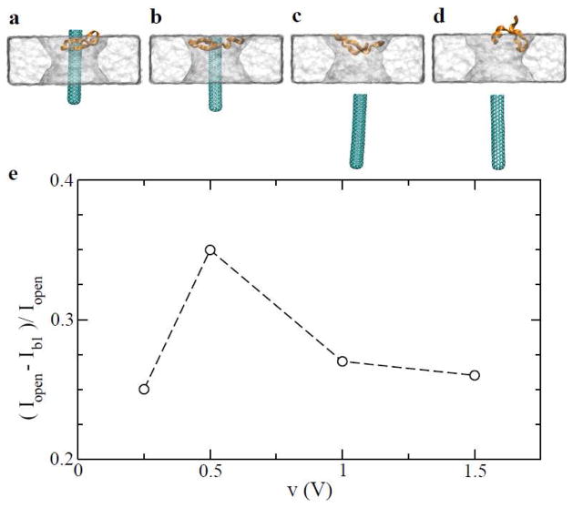
To detect the entry of the complex into the pore, it is important for the signal of current blockage (Iopen-Ib1) to be larger than the noise of an open-pore current. We use the percentage of current blockage, i.e. (Iopen-Ib1)/Iopen, as a measure of signal quality. Fig. 2e shows results obtained from simulations at different biasing voltages (0.25, 0.5, 1.0 and 1.5 V). Time-dependent currents for these cases are summarized in Fig. S1 in SI. The percentage of current blockage is maximal for the critical biasing voltage (0.5 V) since the complex can be pulled as close as possible to the constriction of the nanopore (Fig. 2b, and movie in SI). When Vbias < Vcr, the complex is farther away from the pore constriction (Fig. 2a). When Vbias > Vcr, the rupture of the complex occurs before the complex gets close to the pore constriction (Fig. 2c–d, and movie in SI). Therefore, in both above cases, percentages of current blockage are less than that for Vcr.
Figure 2.
Relating nanoscopic process of the complex translocation through the solid-state nanopore to measurable current signals. (a–d) Snapshots of the complex translocation process at v=0.25, 0.5, 1.0 and 1.5 V, respectively. (e) Percentage of current blockage during the translocation.
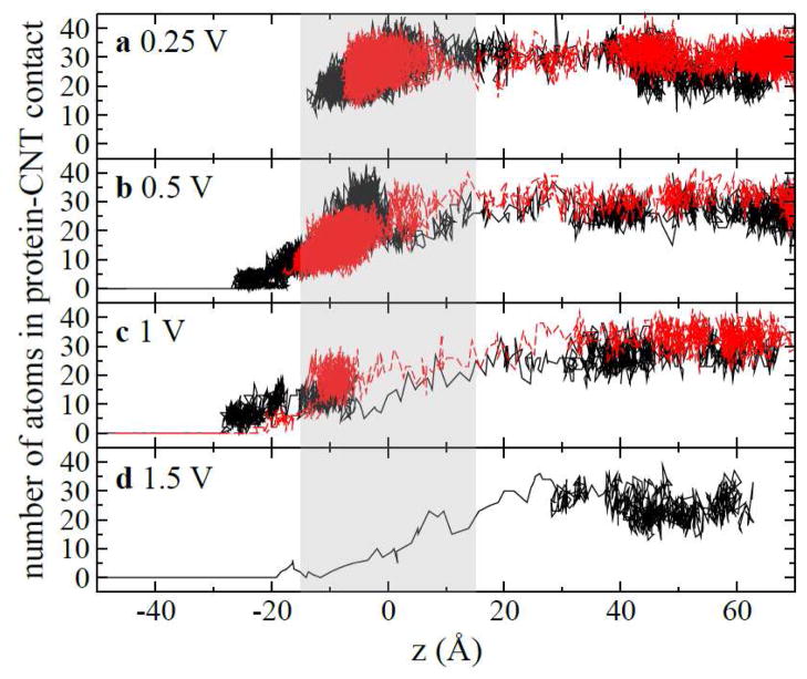
To provide details in protein-CNT interaction during processes of translocation and rupture, we identified non-hydrogen protein atoms that are in contact with (i.e., within 3 Å of) the CNT for each simulation trajectory. In Fig. 3, we show the number of those atoms versus the position (z) of the center of mass (COM) of the CNT in each simulation trajectory. All simulations started when the complex was at least 60 Å above the pore (see Fig. 3). Two independent simulations were carried out for a biasing voltage less than or equal to 1V (Fig. 2a–c). When Vbias=0.25 V, both simulations consistently show that the complex was driven into the pore and was subsequently immobilized inside the pore. For a larger Vbias (0.5 V), the complex can be more deeply brought into the pore (Fig. 3b), which results in a larger percentage of current blockage as shown in Fig. 2e. Meanwhile, the number of contacting atoms decreased since the protein was in contact with the open-end of the CNT. Because of the hydrophobic interaction between the CNT and the protein molecule, an energy barrier (see below) needs to be overcome before the CNT can be pulled through the pore, as shown in one of two simulations (black line in Fig. 3b). After that, the number of contacting atoms is zero. When Vbias is 1 V, Fig. 3c shows that the complex in both simulations breaks apart after being immobilized inside the pore. At an even higher biasing voltage (1.5 V), the CNT moves through the pore without delay (Fig. 3d), indicating a fast rupture process.
Figure 3.
Number of non-hydrogen protein atoms in CNT-WW contact during translocation processes at different voltages. (a) 0.25 V; (b) 0.5 V; (c) 1 V and (d) 1.5 V. In (a–c), red and black lines show results from two independent simulations at the same biasing voltage. The shaded area shows where the nanopore is.
One notable and common characteristics of these electrically driven processes is that the complex moves “slowly” (high density of points in Fig. 3) when distant from the pore but moves relatively faster (low density of points in Fig. 3) when close to the pore. This indicates that the biasing electric field is stronger around the pore than those far away from the pore. Therefore the electrophoretic motion of the complex is faster when the charged part of the CNT enters the pore.
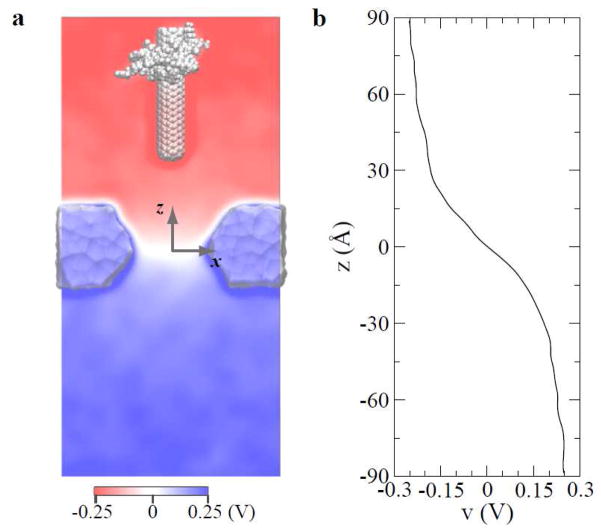
To quantify the distribution of electrostatic potentials in the simulated system, we used Poisson equation to solve potentials16 from atomic positions and charges averaged over 4-ns of simulation. Figure 4a shows a 2D map of electrostatic potentials on the plane (y=0), when the position of the complex is fixed and Vbias = 0.5 V. Potentials are nearly constant far away from pore openings and changes sharply inside the pore. In Fig. 4a, since the lower part of the CNT is negatively charged, potentials there are relatively more negative. Fig. 4b shows potentials on z-axis calculated from a 32-ns simulation for the system without the complex. Consistently, the biasing voltage mainly drops near and inside the pore (−15 Å < z < 15 Å).
Figure 4.
Distribution of electric potentials in simulated systems with a biasing voltage of 0.5 V. (a) two-dimensional map of electrostatic potentials on the y=0 plane. (b) Potentials along the z-axis that coincides with the symmetry axis of the pore. Potentials in (b) were obtained from an independent simulation without the CNT-WW complex.
Theoretically, the ionic current is proportional to (n+μ++n−μ−)e·dV/dz·S, ignoring the contribution from gradients of ion concentrations. Here, n+ and n− are concentrations of cat- and an-ions respectively; μ+ and μ− are mobilities of cat- and an-ions respectively; e is the charge of an electron and S is a cross-section area. Since in a stead-state the ion current is constant, dV/dz is inversely proportional to the cross-section area. The cross-section area of a nanopore is usually much smaller than that of a cis. or trans. chamber, therefore the electric field (dV/dz) inside the nanopore is much larger than fields outside.
From the simulation trajectory of the complex immobilized inside the nanopore, we calculated number of counterions (K+) within 3 Å of the CNT. The aver-aged number of those counterions is 1.4 e (see SI). Therefore, the effective charge qeff of the CNT after counterion screening is 8.6 e and about 14% of CNT’s charge is screened. When Vcr = 0.5 V, Fig. 4b shows that the critical electric field Ecr inside the pore is approximately 6.6 mV/Å. Therefore, the estimated rupture force qeff·Ecr of the complex is ~90 pN.
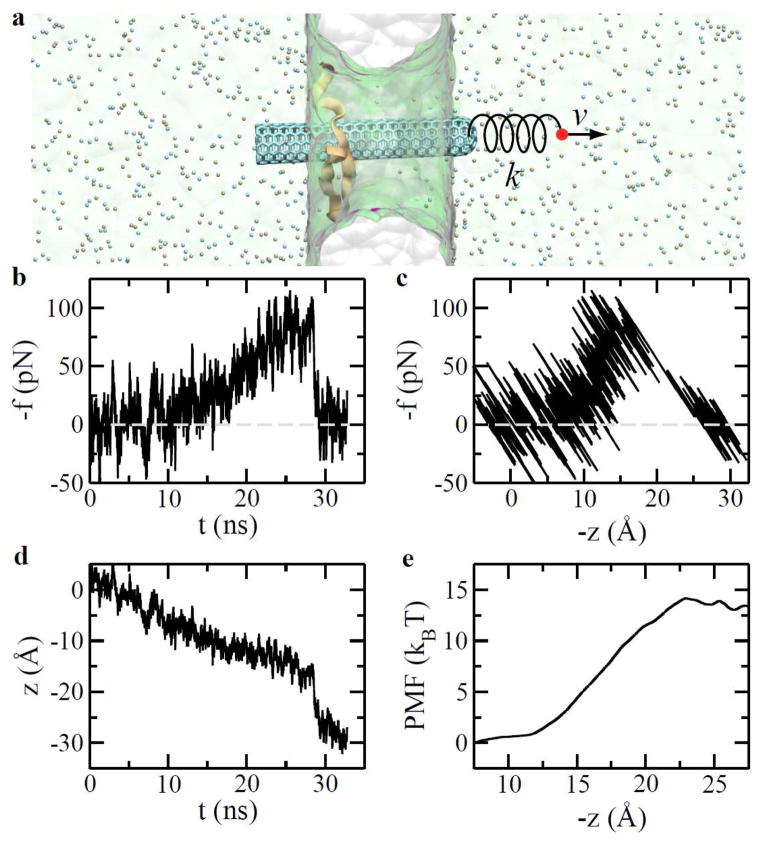
To further quantify mechanics and energetics during the rupture process of the complex, we performed steered molecular dynamics17 (SMD) simulations, as illustrated in Fig. 5a. After the complex was driven into the pore and immobilized inside the pore for about 100 ns (see Fig. 1a), we turned off the biasing voltage (0.5 V) and equilibrated the simulation system for another 4 ns. From this equilibrated system, we started SMD simulations. One end of a harmonic spring (k = 10 pN/Å) was attached to a stage that moves at a constant velocity (1 Å/ns). The other end of the spring was attached to the center of mass of the CNT. Figures 5b and 5c show that forces (in the pulling spring) are dependent on time and positions of the CNT’s COM during the pulling process, respectively. These data reveal two stages of the pulling process. Firstly, the CNT slid through the hydrophobic binding site of the WW domain. Due to the periodic atomic structure of the CNT, the CNT-WW interaction changes periodically and only a small force (a few pico-newtons) is required to move the CNT. In fact, such sliding motion can even be thermally activated. In the second stage, CNT was pulled out of the hydrophobic binding site of the WW-domain. The time-averaged force in spring increased to about 80 pN before the rupture happened. This is comparable with the previously estimated rupture force (qeffEcr). After that, CNT caught up with the pulling stage since the pulling force is much larger than the hydrodynamic friction force (Fig. 5c). Consequently, the force in spring substantially dropped (Fig. 5b) and thereafter balanced the hydrodynamic friction force. This rupture process is also highlighted in Fig. 5d, showing time-dependent positions of the CNT’s COM. The rupture/catching-up process occurred around 28 ns in the simulation.
Figure 5.
Mechanics and energetics in the process of pulling the CNT apart from the WW domain that is immobilized in a nanopore. (a) Steered molecular dynamics simulation. Water (green) is shown transparently. (b) Time-dependent pulling forces. (c) Pulling forces vs. CNT-positions. (d) CNT positions vs. time during the pulling process. (e) Potential of mean force for the complex.
Additional six independent SMD simulations were carried out using a much stiffer spring18 (k = 1000 pN/Å) to pull the CNT off the protein. From these simulations, we used Jazynski equation19 to calculate the potential of mean force (PMF) for the CNT-WW binding. The PMF (Fig. 5e) for the binding is about 13 kBT that is consistent with the previously obtained binding affinity value of ~10 kBT3,20.
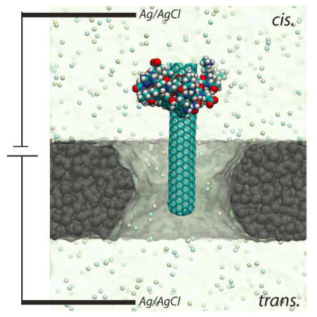
In summary, using proof-of-principle MD simulations, we demonstrated that a nanopore-based electric sensor can potentially be applied for a high-throughput screening of CNT’s binding capability, and thus potential nanotoxicity, to a protein molecule. To allow the rupture process, the size of a constriction site (such as a “neck” in an hour-glass-shaped pore) in a fabricated nanopore should be larger than the diameter of a CNT and smaller than the size of a protein molecule. Thus, our proposed sensing method should work for pores with other shapes (e.g. cylindrical and conic ones) if the above requirement is satisfied. Similarly, recent experiments have shown that the complex of a DNA and a DNA-binding protein molecules can be electrically driven towards a nanopore and the DNA molecule can be further threaded through the pore after rupture21,22. The experimental set-up21,22 (same as shown in TOC) can be deployed as a sensor for CNT’s toxicity to proteins. More generally, a nanopore can be used as a force “microscope” to study DNA-protein interaction, CNT-protein interaction (nanotoxicity), and other interaction (e.g. ligand-binding) in a biological complex.
Supplementary Material
Acknowledgments
We thank Yuliang Zhao, Seung-gu Kang and Bruce Berne for helpful discussions. This work is supported by a grant from the National Institutes of Health (R01-HG05110-01).
Footnotes
Supporting Information. Simulation system; Ionic current traces of complex translocation at different biasing voltages; Ionic screening of a charged CNT and movies for translocation of the complex. This material is available free of charge via the Internet at http://pubs.acs.org1–26.
References
- 1.Nel A, Xia T, Madler L, Li N. Toxic Potential of Materials at the Nanolevel. Science. 2006;311:622–627. doi: 10.1126/science.1114397. [DOI] [PubMed] [Google Scholar]
- 2.Porter AE, Gass M, Muller K, Skepper JN, Midgley PA, Welland M. Direct Imaging of Single-Walled Carbon Nanotubes in Cells. Nat nanotech. 2007;2:713–717. doi: 10.1038/nnano.2007.347. [DOI] [PubMed] [Google Scholar]
- 3.Zuo G, Huang Q, Wei G, Zhou R, Fang H. Plugging into Proteins: Poisoning Protein Function by a Hydrophobic Nanoparticle. ACS Nano. 2010;4:7508–7514. doi: 10.1021/nn101762b. [DOI] [PubMed] [Google Scholar]
- 4.Ge C, Du J, Zhao L, Wang L, Liu Y, Li D, Yang Y, Zhou R, Zhao Y, Chai Z. Binding of Blood Proteins to Carbon Nanotubes Reduces Cytotoxicity. Proc Natl Acad Sci. 2011;108:16968–16973. doi: 10.1073/pnas.1105270108. [DOI] [PMC free article] [PubMed] [Google Scholar]
- 5.Branton D, Deamer DW, Marziali A, Bayley H, Benner SA, Butler T, Di Ventra M, Garaj S, Hibbs A, Huang X. The Potential and Challenges of Nanopore Sequencing. Nat Biotechnol. 2008;26:1146–1153. doi: 10.1038/nbt.1495. [DOI] [PMC free article] [PubMed] [Google Scholar]
- 6.Meller A, Nivon L, Brandin E, Golovchenko J, Branton D. Rapid Nanopore Discrimination between Single Polynucleotide Molecules. Proc Natl Acad Sci. 2000;97:1079–1084. doi: 10.1073/pnas.97.3.1079. [DOI] [PMC free article] [PubMed] [Google Scholar]
- 7.Storm AJ, Storm C, Chen J, Zandbergen H, Joanny JF, Dekker C. Fast DNA Translocation through a Solid-State Nanopore. Nano Lett. 2005;5:1193–1197. doi: 10.1021/nl048030d. [DOI] [PubMed] [Google Scholar]
- 8.Wanunu M, Dadosh T, Ray V, Jin J, McReynolds L, Drndic M. Rapid Electronic Detection of Probe-Specific MicroRNAs using Thin Nanopore Sensors. Nat Nanotechnol. 2010;5:807–814. doi: 10.1038/nnano.2010.202. [DOI] [PubMed] [Google Scholar]
- 9.Yusko EC, Johnson JM, Majd S, Prangkio P, Rollings RC, Li J, Yang J, Mayer M. Controlling Protein Translocation through Nanopores with Bio-inspired Fluid Walls. Nat Nanotechnol. 2011;6:253–260. doi: 10.1038/nnano.2011.12. [DOI] [PMC free article] [PubMed] [Google Scholar]
- 10.Manrao EA, Derrington IM, Laszlo AH, Langford KW, Hopper MK, Gillgren N, Pavlenok M, Niederweis M, Gundlach JH. Reading DNA at Single-Nucleotide Resolution with a Mutant MspA Nanopore and Phi29 DNA Polymerase. Nat Biotechnol. 2012;30:349–353. doi: 10.1038/nbt.2171. [DOI] [PMC free article] [PubMed] [Google Scholar]
- 11.Wang Y, Zheng D, Tan Q, Wang MX, Gu LQ. Nanopore-Based Detection of Circulating MicroRNAs in Lung Cancer Patients. Nat Nanotechnol. 2011;6:668–674. doi: 10.1038/nnano.2011.147. [DOI] [PMC free article] [PubMed] [Google Scholar]
- 12.Hall AR, Keegstra JM, Duch MC, Hersam MC, Dekker C. Translocation of Single-Wall Carbon Nanotubes through Solid-State Nanopores. Nano Lett. 2011;11:2446–2450. doi: 10.1021/nl200873w. [DOI] [PMC free article] [PubMed] [Google Scholar]
- 13.Sun YP, Fu K, Lin Y, Huang W. Functionalized Carbon Nanotubes: Properties and Applications. Acc Chem Res. 2002;35:1096–1104. doi: 10.1021/ar010160v. [DOI] [PubMed] [Google Scholar]
- 14.Phillips JC, Braun R, Wang W, Gumbart J, Tajkhorshid E, Villa E, Chipot C, Skeel RD, Kale L, Schulten K. Scalable Molecular Dynamics with NAMD. J Comp Chem. 2005;26:1781–1802. doi: 10.1002/jcc.20289. [DOI] [PMC free article] [PubMed] [Google Scholar]
- 15.Macias MJ, Gervais V, Civera C, Oschkinat H. Structural Analysis of WW Domains and Design of a WW Prototype. Nat Struct Biol. 2000;7:375–379. doi: 10.1038/75144. [DOI] [PubMed] [Google Scholar]
- 16.Aksimentiev A, Schulten K. Imaging alpha-Hemolysin with Molecular Dynamics: Ionic Conductance, Osmotic Permeability, and the Electrostatic Potential Map. Biophys J. 2005;88:3745–3761. doi: 10.1529/biophysj.104.058727. [DOI] [PMC free article] [PubMed] [Google Scholar]
- 17.Isralewitz B, Gao M, Schulten K. Steered Molecular Dynamics and Mechanical Functions of Proteins. Curr Op Struct Bio. 2001;11:224–230. doi: 10.1016/s0959-440x(00)00194-9. [DOI] [PubMed] [Google Scholar]
- 18.Park S, Schulten K. Calculating Potentials of Mean Force from Steered Molecular Dynamics Simulations. J Chem Phys. 2004;120:5946–5961. doi: 10.1063/1.1651473. [DOI] [PubMed] [Google Scholar]
- 19.Jarzynski C. Nonequilibrium Equality for Free Energy Differences. Phys Rev Lett. 1997;78:2690–2693. [Google Scholar]
- 20.Zuo G, Gu W, Fang H, Zhou R. Carbon Nanotube Wins the Competitive Binding over Proline-Rich Motif Ligand on SH3 Domain. J Phys Chem C. 2011;115:12322–12328. [Google Scholar]
- 21.Hornblower B, Coombs A, Whitaker RD, Kolomeisky A, Picone SJ, Meller A, Akeson M. Single-Molecule Analysis of DNA-Protein Complexes using Nanopores. Nat Meth. 2007;4:315–317. doi: 10.1038/nmeth1021. [DOI] [PubMed] [Google Scholar]
- 22.Zhao Q, Sigalov G, Dimitrov V, Dorvel B, Mirsaidov U, Sligar S, Aksimentiev A, Timp G. Detecting SNPs Using a Synthetic Nanopore. Nano Lett. 2007;7:1680–1685. doi: 10.1021/nl070668c. [DOI] [PMC free article] [PubMed] [Google Scholar]
Associated Data
This section collects any data citations, data availability statements, or supplementary materials included in this article.


