Abstract
To demonstrate that crystallographic methods can be applied to index and interpret diffraction patterns from well-ordered quasicrystals that display non-crystallographic 5-fold symmetry, we have characterized the properties of a series of periodic two-dimensional lattices built from pentagons, called Fibonacci pentilings, which resemble aperiodic Penrose tilings. The computed diffraction patterns from periodic pentilings with moderate size unit cells show decagonal symmetry and are virtually indistinguishable from that of the infinite aperiodic pentiling. We identify the vertices and centers of the pentagons forming the pentiling with the positions of transition metal atoms projected on the plane perpendicular to the decagonal axis of quasicrystals whose structure is related to crystalline η phase alloys. The characteristic length scale of the pentiling lattices, evident from the Patterson (autocorrelation) function, is ∼τ2 times the pentagon edge length, where τ is the golden ratio. Within this distance there are a finite number of local atomic motifs whose structure can be crystallographically refined against the experimentally measured diffraction data.
Five-fold symmetry has been associated with magic and mysticism since ancient times. Kepler, in his Mysterium Cosmigraphicum, published 400 years ago, described how he ingeniously found the symmetry of the five Platonic polyhedra in the structure of the solar system. Book II of his Harmonices Mundi (1), on the congruence of harmonic figures, is a pinnacle in the history of geometry, combining imaginative mathematical mysticism with profound insights into the symmetry of polyhedra and polygonal tilings of the plane. Kepler’s exploration of orderly arrangements of plane pentagons has been viewed (2) as an anticipation of Penrose’s aperiodic tilings (3), which have served as models for the geometry of quasicrystal structures.
Quasicrystallography has developed into an elaborate discipline since 1984 when Shechtman et al. (4) first reported crystal-like diffraction patterns with forbidden icosahedral symmetry from aluminum–manganese alloys, and Levine and Steinhardt (5) coined the name quasicrystals for the class of quasiperiodic structures. Exposition of the results of many experimental studies on these novel alloys, and of the efforts of physicists to model their properties are presented in the book Quasicrystals: A Primer, by Janot (6); the mathematical concepts involved in the construction of aperiodic lattices are described in Quasicrystals and Geometry, by Senechal (2).
In their endeavors, quasicrystallographers have used a variety of mathematically sophisticated but physically unrealistic models to analyze aperiodic lattices with icosahedral or decagonal symmetry. Quasicrystal structures have been represented as projections into two- or three-dimensional space from periodic models in five- or six-dimensional space. For example, such procedures have been applied by Steurer and his colleagues to calculate five-dimensional Fourier maps from three-dimensional x-ray diffraction patterns of decagonal-phase aluminum-transition metal alloy quasicrystals (7–9). Projections from these physically abstract five-dimensional constructs produce real space maps, which show correlations with the crystallographically determined atomic arrangements in related periodically ordered alloys (10–12). The success of this five-dimensional quasicrystallographic analysis suggests that, because the diffraction data is only observable in three-dimensional reciprocal space, more conventional crystallographic analysis might be applied to refine real space models of the atomic arrangements in these quasicrystals.
Quasicrystals are, by definition, aperiodic lattices. The diffraction pattern from one portion of such a lattice is indistinguishable from that of another portion. A representative portion of a quasicrystal lattice can be chosen as a large unit cell of a perfectly periodic lattice, which would yield the same diffraction pattern as the aperiodic lattice. A great variety of such periodic lattices can be constructed by selecting different portions of the aperiodic lattice as the unit cell. The fact that such lattices exist suggests that one member of this class might be transformed into any other member by localized displacive rearrangements of the constituent atoms.
Our surmise is that quasicrystals with icosahedral or decagonal symmetry may be modeled by periodic packing arrangements of icosahedra or pentagons in moderate-size unit cells that can be locally rearranged, conserving key bonding relations, to generate aperiodic lattices. In this paper, we focus on regular arrangements of pentagons in the plane, applying the same sort of packing rules as used by Dürer (13), Kepler (1), and Penrose (3) in their explorations of pentagonal tilings. The designs of these regular pentagonal tilings are related to the arrangement of transition metal atoms projected on the plane perpendicular to the axes of local 5-fold symmetry in the alloys with aluminum of the crystallographically regular η phase (10–12) and the decagonal quasicrystals (7, 8).
Graphics Methods
To visualize the regular arrangements of pentagons (pentilings), their relation to crystal structures, quasicrystal diffraction patterns and Patterson functions, special purpose graphics routines were developed. All images were created and rendered using unique code in the postscript language (14). Pentilings were created using recursive routines, and coordinates needed for Fourier analyses were generated from the postscript code using the Aladdin Ghostscript interpreter. Once in Protein Data Bank (PDB) format, the coordinates were used with the ccp4 package (15) to calculate electron density maps, structure factors, and Patterson maps. The maps were converted to grayscale images and then embedded in postscript documents. The construction of twinned lattice images and montages used the postscript clipping and superposition capabilities.
Pentilings
We define a pentiling as an arrangement of regular pentagons in the plane in which each pentagon makes edge-to-edge contact with two, three, four, or five neighbors, thereby sharing vertices in such a way that no gaps large enough to contain another pentagon are left in the array. A periodic pentiling is a regular lattice with P pentagons in the unit cell. P is called the pentile number.
The simplest and most compact periodic pentiling is the first tile pattern formed by pentagons described by Dürer (13) in A Manual of Measurements of Lines, Areas, and Solids by Means of Compass and Ruler, which he published in 1525. This tile pattern (which was illustrated by Dürer in his figure 24) is shown in Fig. 1a. The pentile number for this lattice is P0 = 2, the zero subscript indicating that this is the fundamental member of its class.
Figure 1.
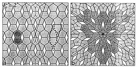
Dürer’s pentilings. (a) The repeating unit of the P0 = 2 pentiling consists of two pentagons (darkly shaded) and one lozenge gap arranged with c2mm plane group symmetry. The primitive unit cell is marked by solid lines or broken lines in the alternate lozenge shape. The pair of 36° wedge regions, comprising a fifth of the pentile lattice, was used to construct the pentagonally twinned lattice (b) by applying 5-fold rotation symmetry about the central pentagon. The twinning of the P0 = 2 pentiling does not alter the local coordination pattern marked by dotted lines. The 10 boundary twinning lines mark rows of pentagons that are shared by neighboring P0 = 2 lattice domains oriented at 36° to each other. The darkly shaded pentagons simulate Dürer’s illustration of this twinning pattern (13).
The repeating motif of the P0 = 2 pentiling
(Fig. 1a) consists of the two regular pentagons of edge
length E and the 36° lozenge gap, also with edge length
E. The crystallographically defined unit cell is the
parallelogram with short axis a0 =
τE, long axis b0 =
τ2E, and included angle γ = 108°, where
τ is the golden mean (τ = τ2 − 1 =
τ−1 + 1 = ½( +1) = 2 Cos 36° =
(2 Sin 18°)−1 = 1.618034… ). The unit cell can also
be represented by the 36° lozenge of edge length
τ2E. Because the ratio of the edge length of
the unit cell lozenge to that of the gap is τ2, the
fraction of the unit cell area occupied by pentagons, defined as the
packing density, is ρ0 = (1 − τ−4) =
0.854102. Each pentagon is joined to three neighbors, thus the
coordination number is C0 = 3.
Dürer (13) demonstrated that the P0 = 2 pentiling can be perfectly pentagonally twinned (Fig. 1b). He wrote: “you can combine pentagons in the following manner: First draw a pentagon and place pentagons of the same size on each side. Then place … pentagons on their sides … . This will result in the formation of five narrow lozenges between them. Then add pentagons in the angles which will have formed, so that these will touch the narrow lozenges with their corners. You can continue in this manner as long as you desire”. The twinning interrupts the regular translational symmetry and produces one five-coordinated pentagon, but does not alter any of the other local contact relations.
Dürer’s P0 = 2 pentiling appears in various guises in the structure of matter. For example, this pattern was found by Kiselev and Klug (16) in the cylindrical surface lattices formed by pentamers of papovavirus coat proteins, which they called pentamer tubes. In the 72 pentamer icosahedral virus capsids of this oncogenic family (17), the 12 pentavalent pentamers make edge-to-edge contacts with their neighbors, as in the pentagonal dodecahedron; but the 60 hexavalent pentamers use, in addition to an edge-to-edge contact, one overlapped corner and two point-to-point contacts. In various polymorphic aggregates of polyoma virus pentamers (18), different combinations of these adaptable contacts occur. Thus, the polymorphic packing of these virus pentamers is too complex to be analyzed using the simple pentiling notions that are appropriate for decagonal quasicrystals.
Crystalline η Phase Alloys
The arrangement of transition metal atoms in the crystalline, η phase alloys with aluminum can be modeled in two-dimensional projection by Dürer’s P0 = 2 pentiling. Fig. 2 illustrates the projected atomic structure of the FeAl3 intermetallic compound determined by Black (10). All the crystals he examined were twinned. One of the twinning arrangements he inferred from his atomic model (11) is illustrated at the right side of Fig. 2. The regular pentiling does not perfectly fit the map of Black’s projected unit cell because the ratio of the long to short axes from his measurements is 1.6108 ± 0.0005 rather than the expected golden ratio 1.6180, and his included angle is 17′ short of the expected 108°. These discrepancies are so small that they are hardly discernible in the frame of this figure, which contains about 18 of the 7.745 × 12.476 Å two-dimensional unit cells. (In three dimensions, the lattice is c face centered, which doubles the 7.745 Å a axis for the crystallographic unit cell.)
Figure 2.
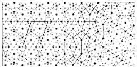
Projected electron density map of FeAl3 η phase alloy and superimposed P0 = 2 pentile lattice. The density map was constructed from the atomic coordinates (10), applying a temperature factor of 5 Å2 to all atoms and projecting the density on the plane perpendicular to the monoclinic b axis. The twinning was modeled by rotating a portion of the map by 36° and rejoining as illustrated in Fig. 1b. The regular P0 = 2 pentiling, marked by the broken lines, closely fits the projected density map with the iron atoms located at the vertices and centers of the pentagons of mean edge length E = 4.78 Å. The common set of pentagons at the twinning boundary is marked by solid lines, with portions of the pattern connecting pentagon centers on either side of the boundary indicated by fine broken lines.
The dark electron density peaks in Fig. 2 correspond to projections of pairs of iron atoms along the direction of the 8.083 Å monoclinic axis. It is evident that the iron atoms, in projection, are located very nearly at the vertices and centers of the regular pentagons of the P0 = 2 pentiling. The arrangement of the lighter aluminum atoms surrounding the iron atoms, as seen in the projected electron density map, is more complicated, but these details will not concern us in relating possible arrangement of the transition metal atoms to various pentilings.
Cobalt and aluminum form an η phase alloy (12) with structure and twinning very similar to that of FeAl3, with which it forms solid solutions. The projected unit cell dimensions of 7.592 × 12.340 Å with included angle 107°54′ are close to those of the iron alloy. For the cobalt alloy, the axial ratio is 0.46% greater than τ, whereas with iron it is 0.44% smaller. There are some small but non-trivial differences in the number and arrangement of the aluminum atoms in these two crystals, which suggest some adaptability in the aluminum coordination that maintains the pentagonal arrangement of the transition metal atoms in different lattices and different environments. For example, along the twinning line marked in Fig. 2, the iron atom arrangement is common to the differently oriented lattice domains, but small localized rearrangements of some of the aluminum atoms must be involved in this meshing.
In the iron and cobalt η phase alloys, the transition metal atoms are arranged at the corners of pentagons of mean edge lengths 4.78 and 4.70 Å in flat planes separated by 4.04 and 4.06 Å, respectively, in the direction of the monoclinic axes of double these separations. The transition metal atoms on the pentagon axes are located about 0.25 Å above or below the midplane of the pair of pentagons and are spaced alternately closer together and further apart along the axes of the pentagonal prisms. In each column the shorter axial separation is opposite the longer separation in the three neighboring prisms. Some of the details of the three-dimensional arrangement of the transition metal atoms in the pentagonal prisms of the η phase crystals will be relevant for considering possible quasicrystalline arrangements. But what we are concerned with at this point is the question: Are there periodic pentilings that can conserve the local pentagonal arrangement of the two-dimensionally projected η phase lattice, which would allow discrete disordering to form a quasiperiodic lattice? It is evident that localized displacive rearrangements of the pentagons cannot be made in the regular P0 = 2 pentiling.
Kepler’s Pentagon Tiling
Consideration of Kepler’s orderly arrangements of pentagons (1) led to insight into ways in which periodic pentilings may be aperiodically disordered. Kepler’s tiling with pentagons and decagons from figure Aa of his Harmonices Mundi Book II is shown in a computer graphics facsimile in Fig. 3a. Senechal (2) considered this a nonrepeating pattern and concluded that Penrose’s first pentagonal tiling family (3) (see Fig. 6) is essentially a completion of Kepler’s figure Aa. In his description of the procedure he used to combine pentagons and decagons in this figure, Kepler commented: “If you really wish to continue the pattern, certain irregularities must be admitted, two decagons must be combined … . So as it progresses this five-cornered pattern continually introduces something new”. However, examination of his pattern shows that a basic repeating unit can be outlined by connecting the star centers to form the elongated hexagons marked in Fig. 3a. These hexagon units have exactly the same shape and packing arrangement as those formed by connecting the pentagon centers in Fig. 1b of Dürer’s perfect pentagonal twinning of the P0 = 2 pentiling. Adding pentagons to extend the regular pattern of Kepler’s tiling, we can say with Dürer: “You can continue in this manner as long as you desire”.
Figure 3.
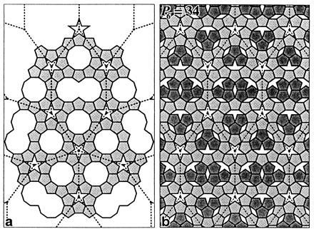
(a) Kepler’s tiling with pentagons and decagons (1) and (b) a P = 34 pentiling generated from Kepler’s matrix. The pattern formed by connecting the pentagrams in a can be continued indefinitely, as in Fig. 1b, to construct a perfect pentagonal twin of the elongated hexagonal units comprised of 22 pentagons, 2 decagons, 2 fused decagons, and 2 pentagrams. By arranging Kepler’s matrix unit with translational symmetry and filling the decagonal spaces with 12 pentagons, a regular P = 34 pentiling is formed in b. Flipping some of the pentagons at random will produce an aperiodic tiling.
Figure 6.
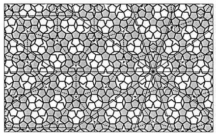
Superposition of Kepler’s and Penrose’s pentagon tilings. Penrose’s tiling (3), marked by the boldly outlined pentagons, is a perfect 5-fold twin of the P8 = 89 pentiling whose unit cells are marked by the portions of the lightly outlined 36° rhombs centered on the starred pentagon. This facsimile of his tiling has been extended 11% to the left of his margin to give the frame a golden aspect ratio. Kepler’s pentagonally twinned matrix of shaded pentagons, from Fig. 3a, is centered on a pentagram in a region of Penrose’s tiling that has only local 5-fold symmetry. The 11 sites within this frame at which pentagon flips are necessary to transform from Penrose’s to Kepler’s pattern can be recognized by the shaded pentagons that do not match the bold outline. Kepler’s matrix cells, outlined with dashes, each contain an isomer of the P6 = 34 unit, which can be distinguished by the orientation of the 12 pentagons inside the decagonal spaces. Curiously, four of these cells contain the same isomer. The density of the P6 = 34 pentiling is 0.0148% greater than that of P8 = 89, which amounts to one more pentagon in an area ≈20× that shown here.
Kepler’s repeating unit can be assembled into a lattice with perfectly regular translational symmetry, as shown in Fig. 3b. Each decagonal cavity can be fitted with three pentagons and each pair of fused decagons with six. This completed tiling has pentile number P = 34. The 3 pentagons in each decagon can be placed in 10 different orientations conserving the number of possible edge-to-edge contacts. There are 52 ways in which the 6 pentagons can be fitted into the fused decagon pair conserving edge-to-edge contacts. (There are 12 more ways that these pentagons can be fitted without overlap that sacrifice an edge-to-edge contact, but these are excluded by our local packing rule for optimizing contacts.) Therefore, there are 5200 ways in which 12 pentagons can be added to Kepler’s 22 pentagon matrices to conserve the number of contacts and packing density. (There are, however, only 1314 combinations with non-identical autocorrelation functions, counting up-down and enantiomorphic pairs only once.) The pentagons forming Kepler’s matrix can also be conservatively reoriented. For example, the five pentagons bordering each pentagram can be flipped in 15 different combinations. Thus, there are an extremely large number of isomers of the P = 34 pentiling, and a larger number of ways in which any of these regular lattices can be discretely disordered, conserving the number of contacts and packing density.
It is evident that the transition metal atoms in the η phase alloys could be arrayed in pentagonal columns corresponding to the pentagons of any of the isomeric or discretely disordered P = 34 pentilings, conserving very similar local packing arrangements. Our surmise is that all the isomers and discretely disordered versions of the P = 34 pentiling just described will have very similar autocorrelation functions and, therefore, similar diffraction patterns. We will compare diffraction patterns and Patterson (autocorrelation) functions of different pentilings after more systematic analysis of their designs and packing properties.
Pentangulation
How can the possible periodic pentilings with P > 2 be systematically enumerated? An obvious strategy is that used by Penrose (3) to generate aperiodic tilings with pentagons: starting with a pentagonal array of pentagons, each pentagon was subdivided into six smaller pentagons and the gaps in the array between the larger pentagons were filled with the smaller ones; this process was iterated. Geometers call this process substitution tiling (2). In our application of this substitution tiling strategy to enumerate periodic pentilings, we call the process pentangulation by analogy with the triangulation process used to enumerate possible icosahedral surface lattice designs in the quasiequivalence theory of icosahedral virus construction (19).
As illustrated in Fig. 4, pentangulation of P0 = 2 generates a pentiling with P4 = 13 (the significance of the subscript will be described shortly); pentangulation of P4 = 13 generates P8 = 89; and pentangulation of P8 = 89 generates P12 = 610. The series 2, 13, 89, 610, 4181, … are the fourth order Fibonacci numbers starting with 2. As a reminder, the Fibonacci numbers are defined: Fn+1 = Fn + Fn−1, with F0 = 0, F1 = 1, and F−n = (−1)n−1 Fn; and starting from F0, the series begins 0, 1, 1, 2, 3, 5, 8, 13, 21, 34, 55, 89, … . Thus, the series of pentangulations starting with P0 = 2 have pentile numbers F3, F3+4, F3+8, F3+12, … . The pth pentangulation of P0 (designated by the superscript p★) is: P0 p★= P4p = F3+4p. In general, Pi★ = 7 Pi − Pi−★, where P− ★ is the inverse pentangulation.
Figure 4.
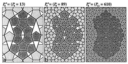
Iterative pentangulation of the P0 = 2 pentiling. The basic pentangulation process is shown in a where six small pentagons are fit into each of the two larger pentagons of the P0 = 2 pentiling, and a single small pentagon is fit into the lozenge gap to generate the P4 = 13 pentiling. The repeating unit of P4 = 13 comprises 13 pentagon centers, 29 pentagon vertices, 1 pentagram, 1 trigram, and 3 lozenge gaps. Because five small pentagons fit in the pentagram gap and three fit in the trigram gap, the next stage of pentangulation (b) generates P8 = 6 × 13 + 5 × 1 + 3 × 1 + 1 × 3 = 89 pentagons. Continuing this process (c), pentangulation of P8 = 89 generates P12 = 610.
At each pentangulation, the ratio of the edge length of the smaller to the larger pentagons is τ−2; or if we consider the pentagon size to remain constant on pentangulation, the edge length of the unit cell will increase by τ2 and its area by τ4. Thus, the fraction of the area occupied by pentagons after the pth pentangulation is ρ4p = P4pα/τ4pA0, where α is the unit pentagon area and A0 is the area of the P0 = 2 unit cell. Since α/A0 = ½ (1 − τ4), ρ4p = (P4p/2τ4p)(1 − τ−4). For P4 = 13, ρ4 = 0.8099767; for P8 = 89, ρ8 = 0.8090374; and for P12 = 610, ρ12 = 0.8090174. It is evident that the pentagon packing density on successive pentangulations starting with P0 = 2 converges to ρ∞ = τ/2 = 0.8090170.
Fibonacci Pentilings
The fact that the pentangulations of P0 = 2 generate a fourth order sequence of Fibonacci pentile numbers, and the P = 34 pentiling generated from Kepler’s net represents another Fibonacci pentile number, suggests that the sequence of pentilings with Pn = Fn+3 may be particularly relevant for characterizing the geometry of decagonal quasicrystals. Nevertheless, it is possible to produce periodic pentilings with any number of pentagons ≥ 2 in the unit cell.
Fig. 5 illustrates regular pentilings for P = 3, 4, 5, and 8. Two versions of P = 4 are shown to demonstrate that this is not a very interesting pentile number. The P = 4a pentiling has exactly the same pentagon packing density as P0 = 2, and can be generated from it by multiple twinning along the oblique rows using Dürer’s scheme shown in Fig. 1b. The alternate P = 4b arrangement has a considerably lower pentagon packing density than any of the other illustrated pentilings. The packing density in any periodic pentiling can be calculated by dividing the area of the pentagons in the unit cell by the total pentagon and gap areas. There are three different size gaps in a regular pentiling that are allowed by our local packing rules: a lozenge L, trigram (Penrose’s “paper boat”) T, and pentagram (star) or allopentagram (as in the P = 4b pentiling) S. The relative areas of these gaps, taking the pentagon area α = 1, are L = 2 (3τ + 1)−1, T = (τ + 3)(3τ + 1)−1, and S = 2τ−1. Thus, ρ(P = 4b) = 2τ−2 = 0.763932. Successive pentangulation of P = 4b gives packing densities that converge to τ/2. (The first pentangulation generates P = 29 with ρ = 0.808057 and the second generates P = 199 with ρ = 0.808997.)
Figure 5.
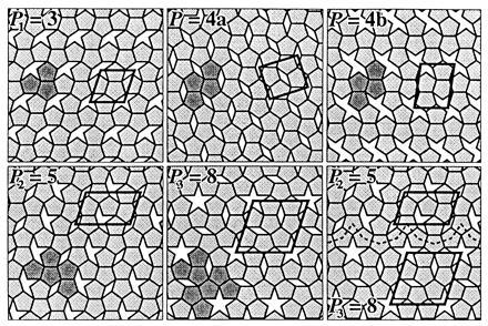
Periodic pentilings with more than two pentagons per unit cell. Pentagons in a repeating unit are shaded and unit cells are marked by solid lines. The regular Fibonacci pentilings P0 = 2, P1 = 3, P2 = 5, and P3 = 8 are the first four members of the series listed in Table 1 whose pentagon packing densities are approximately τ/2. As explained in the text, the two versions of P = 4 illustrated have packing densities that differ significantly from that of the closest Fibonacci pentilings (P1 = 3 and P2 = 5). Different pentiling lattices can be twinned with themselves or each other in various combinations. P = 4a corresponds to periodic twinning of P0 = 2. The illustrated twinning of P2 = 5 and P3 = 8, with the common boundary marked, exemplifies one of the many ways in which periodic pentilings can be combined to generate less regular pentilings.
For the Fibonacci pentilings, as shown in Table 1, the pentagon packing density converges more closely with increasing pentile number to τ/2 than for any other pentiling not in this class. The closer the packing density is to τ/2, the more exactly the periodic pentiling represents the ideal of an infinite aperiodic array. All possible Fibonacci pentilings can be derived by pentangulation starting from the P0 = 2 already described, and the P1 = 3, P2 = 5, and P3 = 8 pentilings illustrated in Fig. 5. Furthermore, these pentilings can all be twinned with themselves, or twinned with each other in various combinations, as illustrated in Fig. 5 for a particular combination of P2 = 5 with P3 = 8.
Table 1.
Fibonacci pentilings
| n | Pn | Vn | (Pn + Vn)/Pn | Cn | (ρn − ρ∞)/ρ∞ |
|---|---|---|---|---|---|
| 0 | 2 | 4 | 3 | 3 | +5.5728 × 10⁻² |
| 1 | 3 | 7 | 3.33333 | 2.66666 | −2.1286 × 10⁻² |
| 2 | 5 | 11 | 3.2 | 2.8 | +8.1306 × 10⁻³ |
| 3 | 8 | 18 | 3.25 | 2.75 | −3.1056 × 10⁻³ |
| 4 | 13 | 29 | 3.23077 | 2.76923 | +1.1862 × 10⁻³ |
| 5 | 21 | 47 | 3.23810 | 2.76171 | −4.5310 × 10⁻⁴ |
| 6 | 34 | 76 | 3.23529 | 2.76471 | +1.7307 × 10⁻⁴ |
| 7 | 55 | 123 | 3.23636 | 2.76364 | −6.6107 × 10⁻⁵ |
| 8 | 89 | 199 | 3.23596 | 2.76405 | +2.5251 × 10⁻⁵ |
| 9 | 144 | 322 | 3.23611 | 2.76389 | −9.6449 × 10⁻⁶ |
| 10 | 233 | 521 | 3.23605 | 2.76395 | +3.6840 × 10⁻⁶ |
| 11 | 377 | 843 | 3.23607 | 2.76393 | −1.4072 × 10⁻⁶ |
| 12 | 610 | 1364 | 3.23607 | 2.76393 | +5.3749 × 10⁻⁷ |
Pentile number Pn = Fn+3 ≡ number of pentagons in unit cell. (Fn+3 is sequence of Fibonacci numbers, starting with 2.) Pentagon vertex number Vn = Pn + 2Pn−1 ≡ number of pentagon vertices in unit cell. Mean number of M atom sites per pentagon (Pn + Vn)/Pn = 2Pn+1/Pn; asymptotic value = 2τ = 3.236068. Mean pentagon coordination Cn = (Pn+1 + Pn−4)/Pn; asymptotic value = τ2 + τ−4 = 2.763932. Pentagon packing density ρn = ½Pnτ−n (1 − τ−4) = ½τ[1 + (− 1)
τ−(2n+6)]; asymptotic value = τ/2 = 0.809017. M atom site density ρn(Pn + Vn)/Pn ≡ ρn(M) = τ2 [1 + (− 1)n+1 τ−(2n+8)]; asymptotic value = τ2 = 2.618034. Values for (ρn(M) − ρ∞(M))/ρ∞(M) = (− 1)n+1 τ−(2n+8) are not listed because this is equal to (ρn+1 − ρ∞)/ρ∞, which is listed for the succeeding pentile number.
It is evident from Figs. 1 and 5 and the rule for pentangulation that the unit cells for Fibonacci pentile numbers of even index (P2m = 2, 5, 13, 34 … ) are 108° parallelograms with edge lengths a = τm+1E and b = τm+2E, where E is the pentagon edge length; for the odd index Fibonacci pentile numbers (P2m+1 = 3, 8, 21, 55, … ) the unit cells are 108° rhombs with edge length a = b = τm+2E. Thus, the area of any of these unit cells with pentile number Pn = Fn+3 is An = τnA0, and the pentagon packing density ρn = Pnα/An = [1/2] Pnτ−n(1 − τ−4). From the definition of Pn and the relations for powers of τ: τn = Fnτ + Fn−1 and τ−n = (−1)n−1 (Fnτ − Fn+1), it can be shown that ρn = ½ τ [1 + (−1)nτ−(2n + 6)]. The fractional pentagon density difference (ρn − ρ∞)/ρ∞ starts at +0.0557281 for P0 and oscillates between negative and positive values of rapidly diminishing magnitude for successive odd and even index pentile numbers, as listed in Table 1.
Other parameters listed in Table 1 that are important for characterizing the Fibonacci pentile packings are the mean coordination Cn, which defines the average number of edge-to-edge contacts per pentagon and Vn, which defines the number of pentagon vertices contained within the unit cell. The sum Pn + Vn = 2Pn+1 corresponds to the total number of sites per unit cell (in projection) that could be occupied by transition metal atoms (M) with the geometry of the η phase illustrated in Fig. 2. The product ρn(Pn + Vn)/Pn ☰ ρn(M) is a measure of the density of M atom sites as a function of the order of the pentile number. From the numbers in Table 1 it can be seen that although the density of pentagon centers in the P0 = 2 pentiling (corresponding to the geometry of the crystalline η phase alloys) is 5.57% greater than that of the limiting aperiodic pentiling, the density of total M sites (pentagon vertices + centers) is 2.13% smaller for the P0 = 2 pentiling than for the aperiodic limit. Thus, less ordered packing arrangements of the pentagonal columns of transition metal atoms can lead to slightly denser M atom packing while maintaining the same nearest neighbor separations. Such a density increase would be accommodated by a reduction in aluminum content.
It is evident from Table 1 that it is not necessary to go to a very large pentile number to reach a pentagon packing density that would be experimentally indistinguishable from the infinite limit of τ/2. Furthermore, the occurrence of only a small number of local motifs in these large period pentilings suggests that ordered lattices with moderate size periods may provide adequate models for less ordered states.
Reordering Pentilings
The larger the pentile number, the larger the number of isomers and the greater the possibilities for introducing discrete disorder by flipping pentagons without altering the mean coordination or packing density (see Fig. 3b). Such local displacive rearrangements can also transform one ordered pentiling into another with comparable packing density. Fig. 6 illustrates the superposition of Kepler’s pentagonally-twinned matrix of pentagons (from Fig. 3a) on the first “aperiodic” tiling presented by Penrose (3). Penrose’s tiling can be represented as the second pentangulation of Dürer’s (13) pentagonally twinned P0 = 2 pentiling to generate the 5-fold twin of the P8 = 89 pentiling. The superposition in Fig. 6 requires 11 pentagon flips within the frame. There are many other ways in which Kepler’s tiling, or regularly periodic versions of it, can be superimposed on Penrose’s tiling, which require different numbers of pentagon flips. These pentagon flips should correspond to energetically equivalent local packing arrangements.
A pentagon flip in atomic terms corresponds to interchanging a pentagon center and vertex in one orientation for a vertex and center in the other. The displacement in the plane of the pentagon for the two sites is E Tan 18°, which, if E = 4.7 Å, involves a lateral movement of 1.5 Å. In the η phase alloys (10, 12), the axial metal atoms sit ≈1.7 Å above or below the pentagonal plane. Interchange of axial and vertex positions would involve coupled movements of ≈2.3 Å. The activation energy for such coordinated movements in columns of atoms might be very high, but could be facilitated by lattice defects designated as phasons in quasicrystallography (6). Even if such flips are rare in the locally well-ordered condensed state, during crystallization columns of atoms would have to choose between pentagon axial and vertex sites. Thus, under conditions favoring a pentagon packing density ρ ≅ τ/2, any of the local atomic arrangements corresponding to moderate-to-larger size periodic pentilings would be equally probable. As we will show, these lattices have virtually indistinguishable diffraction patterns.
Diffraction Patterns and Patterson Functions
“Atomic” models based on several of our Fibonacci pentilings were constructed by placing atoms at the centers and vertices of the pentagons. This construction for P0 = 2 corresponds to omitting the aluminum atoms from the projected map of Black’s (10) η phase FeAl3 structure in Fig. 2. A montage of the modeled diffraction patterns and Patterson functions for P0 = 2, P4 = 13, P6 = 34, and P8 = 89 are shown in Figs. 7 and 8. The arrangement of the pentagons in the P0 = 2 pentiling has orthogonal mirror (mm) symmetry, and arrangements were chosen for the even order pentilings with a line of mirror symmetry perpendicular to the a axis (i.e., along the long axis of the 36° lozenge unit cell). Thus, the Fourier transforms have mm symmetry and the single quadrant displayed for each model in Fig. 7 represents all the diffraction data. The Patterson functions (Fig. 8) were calculated from the squared structure factors illustrated in Fig. 7. All unit cells have the same golden ratio shape because the Fibonacci pentile numbers all have even order indices. The cell dimensions for P0 = 2 are a = τE = 7.60 Å and b = τ2E = 12.30 Å; for P4 = 13, P6 = 34, and P8 = 89 these dimensions are scaled up by τ2, τ3, and τ4, respectively.
Figure 7.
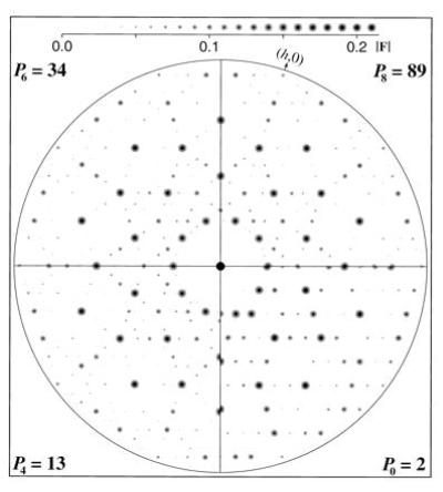
Diffraction patterns of regular pentilings. Model electron density maps similar to Fig. 2 were calculated by placing identical atoms with temperature factors of 5 Å2 at the vertices and centers of pentagons in the P0 = 2, P4 = 13, P6 = 34, and P8 = 89 pentilings from Figs. 1a, 4a, 3b, and 4b, respectively. The pentagon edge length E in this construction is 4.7 Å. Fast Fourier transforms of these maps were calculated to 0.9-Å resolution and the amplitudes were scaled by setting F00 to unity. The maximum scaled amplitude in each pattern is |Fmax| ≈0.2. The quadrants, which include all independent Fourier coefficients for each pattern, are aligned with the (0,k) axis horizontal. The patterns from the higher order pentilings have evident 10-fold symmetry. Comparison across the boundary between the P6 = 34 and P8 = 89 patterns demonstrates that they are virtually indistinguishable. The structure factors, which are discrete points in reciprocal space, are depicted as Gaussian disks with radii proportional to the amplitudes as indicated in the |F| scale at the top. The intensity range displayed is ≈100.
Figure 8.
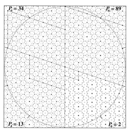
Patterson maps of regular pentilings. Sectors of the four Patterson maps are aligned with their a axes vertical and their unit cells outlined (the b axis of P8 = 89 extends beyond the image frame). The circle has radius 52.4 Å = τ5E, which is equal to the a axis of P8 = 89 and the b axis of P6 = 34, and is marked every 36° to emphasize the 10-fold symmetry.
In both reciprocal and Patterson space, the patterns for P4, P6, and P8 show dominant 10-fold symmetry, characteristic of the averaged pentagonal packing of the pentagons in these moderate size unit cells. Small departures from perfect 10-fold symmetry are evident in the P4 = 13 patterns, but such undecagonal features are more difficult to detect in the P6 = 34 and P8 = 89 patterns. For the P0 = 2 patterns, even though the unit cell axes are at an angle of 108°, there is little indication of 10-fold symmetry. Nevertheless, there are evident correlations in the distribution of the short vectors of the P0 = 2 Patterson function compared with those of its more pentangulated relations, indicative of the common local atomic packing relations.
It has been argued (6) that large unit cell models are inappropriate to represent quasicrystal structures because “unit cells in crystal models have to be so large that they would imply a physically implausible range of interaction”. We are not proposing that any particular crystal model represents the actual atomic arrangement of a quasicrystal. What we have demonstrated is that a wide range of crystal models with common local pentagonal coordination relations have nearly indistinguishable decagonal Fourier transforms and autocorrelation functions. A priori, any one of our crystal models with a moderate size unit cell is as likely a representation of the actual projected arrangement of the transition metal atoms in a defect-free domain of a decagonal quasicrystal (7, 8) as any particular defect-free aperiodic model with pentagon packing density ρ ≅ τ/2. Periodic pentiling models with moderate size unit cells provide a rational foundation for crystallographically refining the actual local atomic arrangements that build up the quasiperiodic decagonal crystal structures.
Quasicrystal Crystallography
For a crystallographer, a crystal is like an orderly forest that is useful for determining the average structure of the trees. The repeating unit may be a clump of trees related by noncrystallographic symmetry or constrained to grow in non-equivalent configurations. These complexities can aid the crystallographer in seeing the trees more clearly. Quasicrystallographers have, however, had difficulty seeing the trees for the forest. The aperiodic space-filling and periodic higher dimensional representations of quasicrystalline forests are mathematically elegant, but these abstractions have tended to obscure sight of the trees. It is evident that these atomic trees are locally ordered in clusters, which are arranged quasiperiodically. How can the structure of these clumps be most clearly visualized?
One way to approach the question of how the atoms are arranged in a quasicrystal is to look at the Patterson function that epitomizes all the information about the interatomic vectors contained in the diffraction pattern. Fig. 9 shows an embellished version of the P8 = 89 Patterson function calculated from the diffraction pattern that is shown indexed in Fig. 10. An obvious feature of the pentiling Patterson emphasized by the circles drawn about the origin and quasiorigins is that the characteristic length scale is ∼τ2 times the pentagon edge length E. The central portion of this Patterson, which is repeated at the quasiequivalent origins, is indistinguishable from that of any pentiling with comparable or larger cell dimensions or from a five-fold average of any of these Pattersons (which would represent the autocorrelation function of the pentiling with infinite size unit cell that is the ultimate quasiperiodic lattice). Thus, the Patterson function solution at the length scale ∼τ2E for a suitable crystalline representation of the decagonal diffraction data is a solution for any crystalline or quasicrystalline representation of this data. This data can be analyzed crystallographically.
Figure 9.
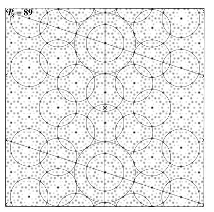
Embellished P8 = 89 Patterson map from Fig. 8. Unit cell axes are marked and the a axis is vertical. The map has mirror symmetry parallel and perpendicular to the a axis at the origin and at a/2 marked with a cross. The centers of symmetry located at the left and right margins are also marked. Circles of radius τE and τ2E are drawn about the crystallographic origins. Circles of radius τE are drawn about a set of quasiequivalent origins related by the local noncrystallographic 10-fold axes and the crystallographic centers of symmetry. Circles of radius τ2E can also be drawn around the quasiequivalent origins, which fit like that about the crystallographic origin.
Figure 10.
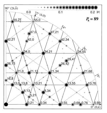
Indexing of the P8 = 89 diffraction pattern. The quadrant in Fig. 7 is enlarged and the most intense spots are labeled with their h,k indices. The thick lines, which are parallel to the crystal axes and are spaced at intervals of consecutive Fibonacci numbers, pass through rows of lattice points including the most intense spots. The thin lines, at angles of ± 36° to the (0,k) direction, are noncrystallographic but nearly pass through centers of the intense spots related by the noncrystallographic 10-fold symmetry.
Quasicrystallographers have concluded that the diffraction maxima in decagonal patterns, such as in Fig. 10, cannot be assigned rational, two-dimensional Miller indices because the Bragg spacings along lattice lines correspond to incommensurate periodicities. There are, however, no incommensurate periodicities in the world of experimental distance measurements. For example, the diffraction pattern from a helix with an irrational screw axis would be indexed by an experimentalist as the Fourier-Bessel transform of a helix with u units in t turns. The exact values of u and t depend on the accuracy with which the ratio of the layer-line spacings corresponding to the helix pitch and unit axial translation can be measured. The more precise this measurement, the larger the calculated repeat distance. Indexing a large helix repeat distance does not imply an implausible range of interaction, but does indicate the skill of the fiber diffractionist in making precision measurements. The same considerations can be applied to indexing experimentally recorded quasicrystal diffraction patterns.
A set of selection rules for indexing the diffraction maxima in the decagonal patterns could be formulated as for helical diffraction, but all that is needed is the choice of pentile model and the rule for indexing the lowest resolution set of strong reflections. Odd and even order pentile numbers correspond to fat and thin golden ratio rhombic unit cells as already noted, and either will represent the decagonal quasicrystal symmetry. For the even order (P2m) Fibonacci pentile diffraction patterns illustrated in Fig. 7, with unit cell dimensions a = τm+1E and b = τa, the index of the first strong (h,0) reflection along the a* axis is h = Pm (= Fm+3); for the first strong (0,k) reflection along the b* axis, k = Pm+1 (= Fm+4); and for the first (h,k) reflection at ≈36° between the (h,0) and (0,k), h = Pm−1, k = Pm. These three reflections have very nearly the same Bragg spacing. For the P8 = 89 diffraction pattern in Fig. 10 for which m = 4, the ratio of the spacings d*0,21 : d*8,13 : d*13,0 is 1 : 0.99949 : 1.00164. For higher resolution decagonally related reflections or for higher order pentiling lattices, these ratios approach much closer to 1 (e.g., d*34,0/d*0,55 = 1.00024 and d*0,89/d*55,0 = 1.00009). An experimental diffraction pattern can be represented as the 5-fold average of a pentile model pattern that best fits the measured width of the Bragg reflections.
A curious feature of quasicrystal diffraction patterns, associated with what is called phason disorder, is a sharpening of the diffraction peaks with increasing angle (20). Such resolution-dependent peak sharpening for decagonal quasicrystals can be accounted for by pentagonal averaging of diffraction from pentile lattice domains with relatively small pentile number. For a multiply twinned mosaic of such domains (see Fig. 5), whose densities vary above or below the asymptotic value for higher order pentilings (Table 1), the effect on the diffraction pattern would be to enhance small angle diffuse scatter and average decagonally related Bragg peaks with slightly different spacing. This peak broadening would progressively diminish for higher resolution reflections.
Decagonal Quasicrystal Structures
The two-dimensional pentile lattices appear to provide reasonable trial models for the projected arrangement of the transition metal atoms in the plane perpendicular to the 5-fold axes of decagonal quasicrystals such as Al65Cu20Co15 (7) and Al70Ni15Co15 (8). The Bragg spacings for the first equatorial decagonal set of strong reflections—which have been given five-dimensional indices (10000)—are 3.765 and 3.794 Å, respectively, for these two quasicrystals. The indexing of a pentile lattice diffraction pattern (Fig. 10) indicates that the mean spacing of this set of strong reflections is the limiting value of (Pm)−1τm+1E Cos 18°. The asymptotic value of (Pm)−1τm+1 = τ−1 + τ−3 = 1 − τ−4 = 0.854102. Thus, the mean pentagon edge lengths corresponding to the Bragg spacings of 3.765 and 3.794 Å are E = 4.635 and 4.671 Å, respectively. These values are in good accord with the density maps projected from the calculated five-dimensional Fourier (7, 8) and the mean edge length of 4.70 Å for the η phase Al13Co4 alloy (12).
There are many fascinating aspects to the decagonal quasicrystal diffraction patterns obtained by Steurer and colleagues (7, 8). The satellite reflections around the strong Bragg maxima are suggestive of ghost spectra (21) due to microdomain structure or directional quasiperiodic density fluctuations on a long distance scale. The pronounced small angle diffuse scatter is characteristic of uncorrelated density fluctuations on a long-to-moderate distance scale. The strongly modulated diffuse diffraction on the odd order 8.08-Å layer planes perpendicular to the pentagonal prism axes is related to absence of long-range lateral correlations in the up-down displacements of the axial metal atoms that are regularly staggered between adjacent columns in the η phase alloys (10, 12). Analysis of this diffuse scatter, applying methods developed in protein crystallography (22), could provide a measure of the decay distance for the lateral correlations in the axially staggered displacements and the magnitude of the mean square fluctuations in the lateral positions of the variable atoms.
From the density maps derived by five-dimensional Fourier analyses of the decagonal quasicrystals (7–9) it should be possible to construct real space models, which could be refined against the diffraction data using conventional crystallographic least squares methods. The characteristic distance scale evident from the Patterson function (Fig. 9) indicates that the distinctive structural motifs need only be modeled to distances ∼τ2E ≅ 12 Å, which corresponds, for example, to the vertex-to-vertex span of a pentagram or the center-to-center separation of a pair of pentagons attached to the non-adjacent sides of a central pentagon. Within this distance, there are a finite number of motifs, all or most of which will be represented in any reasonable size periodic pentile lattice. Individual pentagons can be five-, four-, three-, or two-coordinated. The metal atoms at the vertices of a five-coordinated pentagon would be expected to be equivalently related; but in all other pentagon environments, these atoms will be quasiequivalently related, as in the crystalline η phase structures (10–12), which means that the five edge-length distances need not be exactly equal.
Experimental diffraction data for the vectors between the transition metal atoms can be obtained by multi-wavelength anomalous dispersion measurements. These data would also identify possible correlations in the positions of the two types of transition metals in the stable decagonal quasicrystals. Having established the number of independent variables for these metal atom–metal atom vectors, these vector distances could be refined within the framework of any reasonable size three-dimensional periodic pentile lattice. The number of parameters required to refine all the possible aluminum atom configurations in the distinguishable environments is likely to exceed the 253 independent structure factor terms that have been measured to 0.5-Å resolution for the Al70Ni15Co15 decagonal quasicrystal (8). In this case, stereochemical and energetic restraints could be applied to refine the structure as in macromolecular crystallography (23, 24).
Conclusion
We have demonstrated that in the decagonal quasicrystalline realm the Emperor need not wear five-dimensionally quilted quasiclothes, and we surmise that similar six-dimensional garments will prove to be unnecessary in the icosahedral quasicrystalline domain.
Acknowledgments
We thank Bin Yu for assistance with the crystallographic calculations. This work has been supported by U.S. Public Health Service Research Grant CA47439-08 from the National Institutes of Health’s National Cancer Institute.
References
- 1.Kepler, J. (1619) Harmonices Mundi [Facsimile edition (1969) (Forni Editore, Bologna, Italy); Book II: On the Congruence of Harmonic Figures, English transl., J. V. Field (1979) Vistas Astron. 23, 109–141].
- 2.Senechal M. Quasicrystals and Geometry. Cambridge, U.K.: Cambridge Univ. Press; 1995. [Google Scholar]
- 3.Penrose R. Math Intelligencer. 1979;2:32–37. [Google Scholar]
- 4.Shechtman D, Blech I, Gratias D, Cahn J W. Phys Rev Lett. 1984;53:1951–1953. [Google Scholar]
- 5.Levine D, Steinhardt P J. Phys Rev Lett. 1984;53:2477–2480. [Google Scholar]
- 6.Janot C. Quasicrystals: A Primer. Oxford: Clarendon; 1992. [Google Scholar]
- 7.Steurer W, Kuo K H. Acta Crystallogr B. 1990;46:703–712. [Google Scholar]
- 8.Steurer W, Haibach T, Zang B, Kek S, Lück R. Acta Crystallogr B. 1993;49:661–675. [Google Scholar]
- 9.Haibach T, Steurer W. Acta Crystallogr A. 1996;52:277–286. doi: 10.1107/s0108767398007272. [DOI] [PubMed] [Google Scholar]
- 10.Black P J. Acta Crystallogr. 1955;8:43–48. [Google Scholar]
- 11.Black P J. Acta Crystallogr. 1955;8:175–181. [Google Scholar]
- 12.Hudd R C, Taylor W H. Acta Crystallogr. 1962;15:441–442. [Google Scholar]
- 13.Dürer, A. (1525) A Manual of Measurement of Lines, Areas and Solids by Means of Compass and Ruler [Facsimile Edition (1977) (Abaris Books, New York), translated with commentary by W. L. Strauss].
- 14.Adobe Systems (1990) postscriptLanguage Reference Manual (Addison–Wesley, Reading, MA), 2nd Ed.
- 15.Collaborative Computational Project Number 4. Acta Crystallogr D. 1994;50:760–763. [Google Scholar]
- 16.Kiselev N A, Klug A. J Mol Biol. 1969;40:155–171. doi: 10.1016/0022-2836(69)90465-3. [DOI] [PubMed] [Google Scholar]
- 17.Rayment I, Baker T S, Caspar D L D, Murakami W T. Nature (London) 1982;295:110–115. doi: 10.1038/295110a0. [DOI] [PMC free article] [PubMed] [Google Scholar]
- 18.Salunke D M, Caspar D L D, Garcea R L. Biophys J. 1989;56:887–900. doi: 10.1016/S0006-3495(89)82735-3. [DOI] [PMC free article] [PubMed] [Google Scholar]
- 19.Caspar D L D, Klug A. Cold Spring Harbor Symp Quant Biol. 1962;27:1–24. doi: 10.1101/sqb.1962.027.001.005. [DOI] [PubMed] [Google Scholar]
- 20.Stephens P W, Goldman A I. Sci Am. 1991;264(4):44–53. [Google Scholar]
- 21.James R W. The Optical Principles of the Diffraction of X-Rays. London: G. Bell and Sons; 1954. [Google Scholar]
- 22.Clarage J B, Clarage M S, Phillips W C, Sweet R M, Caspar D L D. Proteins. 1992;12:145–157. doi: 10.1002/prot.340120208. [DOI] [PubMed] [Google Scholar]
- 23.Hendrickson W A, Konnert J H. In: Biomolecular Structure: Conformation, Function and Evolution. Srinivasan R, editor. Vol. 1. Oxford: Pergamon; 1981. pp. 43–57. [Google Scholar]
- 24.Brünger, A. T. (1990) x-plorManual (Yale Univ., New Haven, CT), Version 2.1.


