Abstract
Personalized therapies play an increasingly critical role in cancer care; Image guidance with multimodality image fusion facilitates the targeting of specific tissue for tissue characterization, and plays a role in drug discovery and optimization of tailored therapies. PET, MRI and contrast enhanced CT may offer additional information not otherwise available to the operator during minimally invasive image guided procedures such as biopsy and ablation. With use of multimodality image fusion for image-guided interventions, navigation with advanced modalities does not require the physical presence of the PET, MRI, or CT imaging system. Several commercially available methods of image fusion and device navigation are reviewed along with an explanation of common tracking hardware and software. An overview of current clinical applications for multimodality navigation is provided.
Introduction
Personalized therapies play an increasingly critical role in cancer care1–3; Image guidance with multimodality image fusion facilitates the targeting of specific tissue for molecular profiling and characterization, and plays a role in drug discovery and optimization of tailored therapies. PET-fusion guided biopsies are based upon either electromagnetic (EM) tracking or cone beam CT (CBCT) registration, and enable sampling of a specific area within a tumor based upon metabolic activity, prospectively correlating pathology to imaging such as PET activity4. PET, MRI and contrast enhanced CT may offer additional information not otherwise available to the operator during minimally invasive image guided procedures such as biopsy and ablation. With use of multimodality image fusion for image-guided interventions, navigation with advanced modalities does not require the physical presence of the PET, MRI, or CT imaging system. Several commercially available methods of image fusion and device navigation are reviewed along with an explanation of common tracking hardware and software. An overview of current clinical applications for multimodality navigation is provided. Image fusion has been implemented in clinical trials for the past 8 years for biopsies and ablations and has been used as a research tool to prospectively correlate imaging features with biomarkers or drug effects5. Although speculative at present, multimodality fusion guidance may enable procedures that would otherwise not be possible 6 or may reduce patient and operator radiation dose, volume of contrast and complication rates. Planning multiple overlapping composite treatment zones may also improve the success of large volume tumor ablation.
Background on Image fusion-guided procedures
Image fusion and co-registration bring several imaging modalities together. Although the terms are often used interchangeably, image fusion is the overlay of two or more imaging datasets together, as one display, whereas image co-registration consists of aligning or matching the two imaging datasets spatially to each other 7. Registration can be rigid or elastic (deformable). Only translation (panning) and rotation are possible with rigid co-registration while rotation, translation and localized stretching are possible with elastic registration which improves matching of anatomical structures. For example a difference in patient positioning between diagnostic and intra-procedural imaging may be corrected by rotating the image but a deformation of an organ secondary to placement of a rigid probe or a stent graft would require localized stretching8. Motion associated with position, organ shift or deformation, and respiratory movement present ongoing challenges to image registration and fusion7. Despite practical limitations, image fusion and registration can improve visualization during image-guided procedures, which may, in turn, improve accuracy by reducing the number of device repositioning required to reach a target, by allowing physician to precisely navigate to a lesion on PET without anatomical correlate on conventional imaging etc… Accuracy may translate into other clinical benefits such as shorter procedure time, reduced radiation to both patients and staff.
Multi-modality image fusion navigation systems
There are several methods to enable navigation during image-guided procedures with co-display of multiple datasets. Each method includes 1) the capability to import previously acquired image datasets to be registered with a selected real-time imaging modality, and 2) the ability to display the position of the procedure device in the fused datasets in static or real-time fashion. Electromagnetic (EM tracking) and optical tracking provide real-time position data for tracked instruments in a virtual space, while cone beam CT (CBCT) based navigation permits registration of 3D datasets with fluoroscopy for real-time instrument localization.
Electromagnetic (EM) tracking
EM tracking is sometimes referred to as “Medical GPS”8,9 and relies on Faraday’s law of induction. A generator creates numerous very weak and differential magnetic fields that turn on and off, within a work volume of about 500mm × 500mm × 500mm. A coil within that magnetic field evokes a weak detectable electrical current, whose signal strength is related to the coil’s location within this changing magnetic field. This changing current is detected and its strength is triangulated and defined by a point in space. This basic physics principle is used to define the coil and device locations within a Cartesian coordinate system8,9. Several coils can be tracked simultaneously. The coils are integrated within medical devices and fiducial skin patches.
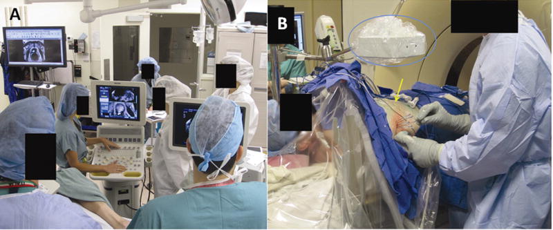
EM tracking requires additional equipment relative to that necessary for a conventional image guided biopsy, including a tracking workstation, field generator and specialized disposables and non-disposables such as tracked needles, stylettes, ultrasound guides and fiducial patches9. However, it offers the advantages of both multimodality image fusion and real time display during an intervention, as well as real time device tracking, as opposed to only intermittent displays of needle angle and position during a conventional percutaneous intervention. Navigation with EM tracking can be accomplished with several different workflows, depending upon the real time modality and the fusion modalities. In many cases, radio-opaque fiducial patches equipped with sensor coils are placed in the area of interest and used for registration achieved by matching their position on procedural imaging to the actual location as detected by the field generator (and verified by tapping on the fiducials with a pointer). A tracked ultrasound probe can also be used for real time fusion imaging, acting as a “multi-planar reconstruction (MPR) plane selector” (figure 1). A procedural CT or ultrasound may be registered to previous imaging modalities such as PET-CT or MRI using anatomical landmarks or scan-plane matching, while automated registration tools are under development, which will facilitate throughput immensely. Tracked devices are navigated to a target, based on the fused modalities, with real time feedback of the position of the device in relation to the fused modalities.
Figure 1.
Picture of the EM tracking set-up. Figure 1a shows the general set-up of an EM tracking procedure with the tracking workstation and an ultrasound. Fiducial patches are placed in the region of interest and procedural CT is obtained. The fiducial patches are used to register the CT in the magnetic space since they contain sensor coils and are radio-opaque. Previous imaging may also be registered rigidly with procedural CT using anatomical landmarks. Figure 1b (middle) centers on the EM field generator (blue circle) as well as tracked devices and the fiducial patches (yellow arrow). All tracked devices within the field of view of the EM generator will be displayed on procedural CT or other advanced imaging that was fused.
The registration error is a rough measure of the difference of the skin fiducials’ selected position compared to their calculated position by the tracking software. Thus the registration error represents roughly how well the positional coordinates of the selected imaging modalities are overlaid. Thus, a registration error less than 2mm is required, but is not necessarily synonymous with clinical accuracy. The target to registration error is measured by comparing the difference of the reported tracked device location to its actual position on verification CT8,10. The overall clinical error depends upon the registration error, the target to registration error, and operator error, and is sometimes measured as the distance of the needle tip to a desired point target. EM tracking registration may be hampered by degradation of coil signal (and registration) secondary to the equipment’s proximity to metallic structures e.g. the CT gantry. Most electromagnetic systems have a dynamic registration patch which corrects for patient motion; some systems also offer respiratory gating. Nonetheless respiratory motion and uncorrected organ shifts will influence the target to registration error and overall accuracy.
Optical tracking
Optical systems are inspired by parallax satellite systems, and utilize infrared or laser light emitting diodes localized on (or reflected from) instruments within the field of view of an infrared camera11,12. The infrared light floods a pre-determined work volume and reflects back to the camera from reflective coating on passive tracking markers. Alternatively, active tracking markers can initiate their own light or infrared signal. The tracking markers placed on surgical instruments report and transmit their position and data to the workstation.
Similar to EM tracking, imaging datasets can be obtained and transferred to the tracking workstation for co-registration, fusion or multiplanar display, and real-time navigation. The advantage of optical systems is higher accuracy, however their widespread use has been precluded by the “line of sight” requirement, which is the necessity of a direct unimpeded pathway between camera and tracked instrument8,11,12. This limitation precludes tracking the internal portions of the devices (such as the tip of a flexible bent needle)12. The back end (i.e. needle hub) can be optically tracked and if the instrument is absolutely rigid (non flexible and non deformable), then its internal location (i.e. needle tip location) can be automatically extrapolated
Cone Beam CT (CBCT) based navigation
Cone Beam CT (CBCT) is a 3D data set generated from the rotation of the x-ray source and flat detector (FD) integrated in the angiography / fluoroscopy C-arm suite. CBCT-based navigation technology can be a tool for needle or catheter guidance to a target that may be defined on a intra-procedural CBCT, or prior MRI, PET/CT, or CT. Co-registering live-fluoroscopy with CBCT 3D volume reconstructed from the detector rotation allows the operator to reference the fused imaging during fluoroscopy, combining fusion guidance with real time x-ray guidance. The images of the CBCT or previously acquired imaging (such as an MRI or CT) may be used to determine a target, a skin entry point and plan a path for a device, needle or catheter. The selected virtual device path is simultaneously displayed on real-time fluoroscopy in addition to the fused image (prior 3D data set), enabling complex image-based navigation in the angiography suite13.
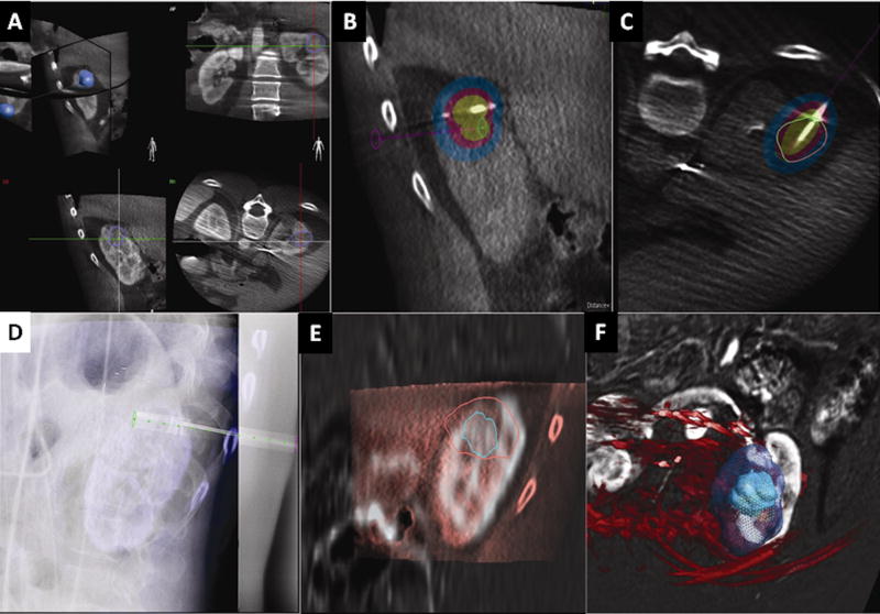
Several methods are available for needle or catheter navigation with fused CBCT. Tumor segmentation can be performed and incorporated into the planning CBCT images to more accurately plan and accomplish ablation or combinational treatment procedures (figure 2). For needle-based procedures, the virtual planned path may be displayed in conjunction with the co-registered data and tumor. For vascular procedures, the target vessels can be identified and isolated semi-automatically with standard processing and segmentation tools (such as ordered region growing). The catheter path may then be displayed on fluoroscopy during selective catheterization. This virtual path and co-registered images adjust with movement of the C-arm or table, assuming patient immobility. One major limitation of CBCT-based navigation is the assumption of immobility and rigidity of anatomy although this is a limitation of all navigation systems including optical tracking and EM tracking. With EM tracking, “dynamic reference tracking” can be used where a tracker is attached to the patient to correct for patient motion. The patient must be kept immobile to ensure that CBCT planned “virtual” path remains rigidly co-registered to the actual anatomy. Any patient movement will require manual correction or repeat registration13. Immobilization pads and “bean-bags” often used in radiation therapy conforms to the patient contours on the table to restrict motion. Tabletop beanbags are connected to a vacuum, and once the patient is positioned, the vacuum removes the air within the bag that becomes a rigid mold. The deflated bag conforms to the patient contours on the table to restrict motion. (Civco, Kalona IA, USA or Body Fix, Elekta, Norcross NC, USA).
Figure 2.
a-b-c-d-e-f: CBCT ablation software platform. This case is a cryoablation of the kidney in a patient with renal cell carcinoma. The tumor is segmented in all 3 planes and displayed as a 3D volume (figure 2a). The virtual ablation probe (green-pink line) is positioned and the ablation zone is displayed with different isotherms (figure 2b). The software displays tumor segmentation (green circle and pink circle) and coverage relative to the probe position indeed when the circle delineating the tumor is green, adequate tumor coverage is expected if it is pink it signifies inadequate tumor coverage (figure 2c). The needle is positioned with X-ray navigation (figure 2d). The cryoablation zone coverage can be corrected according to the final needle position. In this cryoablation case, the iceball obtained (outer circle pink on figure e and green in figure f) can also be compared to segmented tumor (inner green circle on figure e and green circle in figure f) to determine whether an adequate margin was obtained.
Accuracy of EM tracking
Depending upon the exact definition, the accuracy of EM tracking in biopsies and ablations has been reported in a range that is consistent with clinical utility.9,14,15. In an early feasibility study, the overall system accuracy for biopsies with internal needle tip tracking was <5mm9. For vascular phantom experiments, system accuracy was 2.5mm9. A study on neurosurgical phantoms reported a total target localization error ranging between 0.7–3.51mm 16 using EM tracking. The clinical experience using EM tracking for lung biopsies and ablations was reported with a single skin entry puncture and a median of 1 needle repositioning.15 A basic tracking error of 3.8mm ± 2.3mm using EM tracking with skin fiducials and needle tip tracking was reported in 40 patients undergoing biopsies or ablations; this tracking error improved to 2.7 mm ± 1.6mm when previous needle positions were used as additional fiducial markers 6. In the study of Penzkofer et al, twenty three patients underwent image guided interventions with EM tracking navigation with a reported spatial accuracy of 3.1 ± 2.1mm17. In their report, the radiation dose with EM tracking (732 ±481 mGy *cm2) was significantly lower compared to conventional CT guided control non-ablation procedures (1343 ± 1054 mGy *cm2)(p= −0.012)17. The authors concluded that the accuracy and reduced radiation dose of EM tracking justified its routine use.
Accuracy of Optical tracking
Optical tracking is mostly used in surgery in lieu of other stereotactic systems, which are also highly accurate. A deviation of 2.9 mm with optical navigation was reported with CT images as input11. The radiation dose was significantly lower in the optical navigation groups as opposed to the control arm, in phantom and clinical studies 18,19,20.
Comparison of optical vs. EM tracking
Although optical systems generally report higher accuracies in many settings21, one phantom study reported similar accuracies of an EM tracking and two optical systems, and both navigation methods significantly reduced radiation dose and were significantly more accurate than the control group18,22. However, the line of sight requirement has limited the use of optical tracking.
Accuracy of Cone Beam CT (CBCT) navigation
A wide variety of image-guided procedures have been performed with CBCT-based navigation13. CBCT-based navigation was used in phantoms for percutaneous image guided needle placement by Maeda et al.23, with a technical success rate of 93.8% (15/16) for reaching targets successfully on the first needle pass. The mean distance from the needle tip to the target was 3.83± 1.92mm in the successful passes. CBCT-based navigation may be used for vertebroplasties 24, gastrostomies25, dacrocystography dacrocystoplaty and stenting26, biopsies, drainages and ablations27. In the largest series of 139 patients undergoing various needle-based procedures the technical success was 100% (defined as a needle tip position within 5 mm of target). However, accuracy defined as histopathologic diagnosis for biopsies or adequate outcome for therapeutic interventions (i.e. positive aspiration for drainage, successful vertebroplasty, and adequate localization of wire for surgery) was 91.3% for the overall population27. Leschka28 presented accuracy data for CBCT-based navigation in 12 patients. In their series, the technical success rate was 92% (11/12) with deviation from target of 2.8mm or less. One limitation of CBCT is respiratory and patient motion, which can impair registration and decrease accuracy 24.
Clinical applications
Percutaneous non-vascular procedures
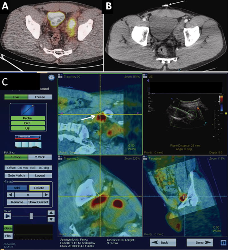
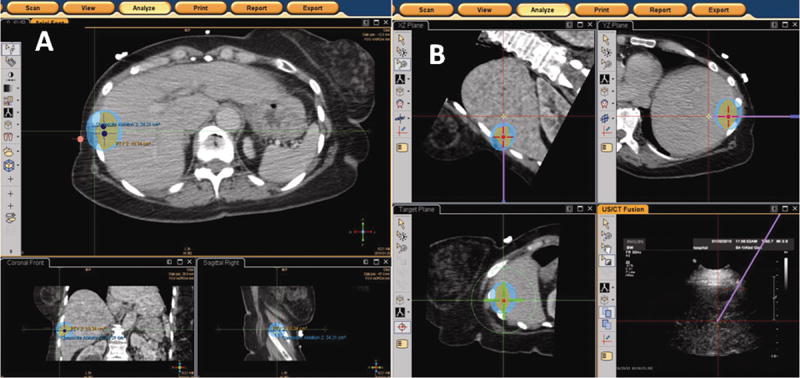
EM tracking may facilitate percutaneous image guided procedures 14,15,29 in certain clearly defined cases. EM tracking offers a distinct advantage in cases where the target lesion is not readily visible with conventional imaging guidance, such as ultrasound and CT without iodinated contrast administration. EM tracking is helpful when lesion visibility is evanescent for example, the lesion is only visible in the arterial phase CT or MR, by obviating the need for repeat injections or inaccurate use of nearby anatomy to estimate needle positioning. Several studies report the usefulness of EM tracking for lesions that are indistinct, heterogeneous or only visible on PET-CT4,8,30 (figure 3). EM tracking may enhance ablation planning and execution, especially if ultrasound visualization is hindered by ablation gas or ice. Ablation planning software enables visualization of the potential ablation zone depending on probe type, number, and position, to facilitate attempts for complete tumor coverage (figure 4). Moreover such planning software can provide iterative feedback during complex ablations that empower the physician to identify tissue at risk for under-treatment, and thereby direct positioning of subsequent ablation probe insertions, if needed8,31–33.
Figure 3.
PET guided fusion case with EM tracking. Image 3a demonstrates an enlarged PET-avid lymph node in a young male with a history of lymphoma in remission for 10 years. The lesion had been previously biopsied at an outside institution and was negative for recurrence or de-differentiation. However the posterior portion of the lesion was not PET-avid. The physician requested a repeat biopsy with 18F-FDG-PET guidance. Fiducial patches (figure 3b) were used to fuse a procedural CT-scan with an ultrasound in the imaging space. A previous PET-CT was fused to the procedural CT using anatomic landmarks. Figure 3c demonstrates the EM tracking platform. The target is shown as a small blue cross hair (white arrow). The needle is displayed as the yellow cross (not shown but the direction of the virtual path can be seen as the yellow dotted line in certain views). The lower right screen shows a bull eye’s view; the red circle converges as the needle advances closer to the target. Real-time ultrasound with Doppler interrogation enables assessment of blood vessels in proximity to the target (upper right screen).
Figure 4.
a–b: Figure 4a [left] and 4b [right] Screenshot display of EM tracking-based ablation planning software platform. The software enables the operator to segment the tumor, which is displayed as an orange-colored circle. The expected treatment area is shown as the blue ellipse. Positions of the RF probe required to achieve the desired tumor coverage are shown as the navy dots (figure 4a). The operator can navigate to the desired probe locations and adjust the treatment plan if the needle positioning deviates from the plan. The virtual needle path is overlaid on both the multiplanar reconstructions (purple solid line) and on the “bull’s eye” view (green crosshairs).
As with EM tracking, several authors have presented their experience with CBCT-based navigation whether for routine procedures 13 or more complex cases such as embolization of jugular paragangliomas 34 or cardiac ablation35.
Navigation may be most useful when access angles are challenging or lesions have limited visibility. Implementation of CBCT-based navigation may become more accessible, based upon wide availability of C-arms suites in current clinical practice. CBCT may also result in improved patient throughput in clinical settings where the conventional CT scanners are heavily employed for diagnostic studies. EM tracking requires hardware and disposables. EM tracking might be preferable in pediatrics since it may have less radiation than CBCT-based navigation that utilizes fluoroscopy. However no study has directly compared the two modalities. Moreover EM tracking may have strengths when real-time ultrasound imaging would be advantageous, such as a lesion surrounded by bowel or in proximity with vasculature. CBCT may have strengths for use with chest procedures with respiratory motion, which can be monitored with registered fluoroscopy (whereas ultrasound cannot see into the lung).
Vascular procedures
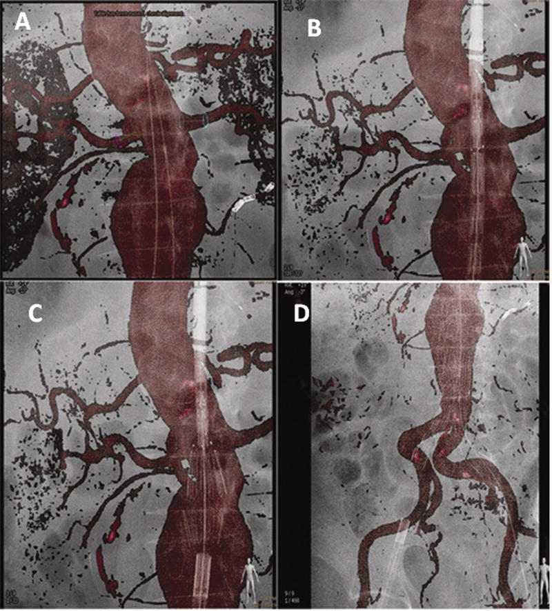
EM tracking has been reported as experimental guidance for endovascular procedures such as stent graft deployment in phantom and swine 9,36,10. Successful deployment of the stent graft was guided without covering the subclavian artery (and without fluoroscopy). EM tracking could have a role for fenestrated grafts and in operating rooms where advanced angiography systems are often not available. Software for the fusion of intra-operative CBCT with previously acquired multi-detector CTA or MRA datasets is commercially available and has shown promising results in reducing contrast and radiation exposure to patients and facilitate complex procedures 37. CTA or MRA volumes are overlaid with an intra-operative low-dose CBCT; this step is performed automatically or by selecting common landmarks like calcifications, clips or vessel borders, excluding the need for contrast injection. The 3D CTA/MRA volumes can then be used as the background map for real-time navigation and deployment of endovascular devices and replace multiple 2D angiograms, 2D roadmaps, or “fluorofade” (figure 5). An additional advantage of 3D dataset fusion is that movements of the C-arm, flat detector and table are compensated, integrated, and corrected, thus making the 3D dataset usable throughout the procedure. CBCT fusion imaging with multi-detector CT was used to guide fenestrated endograft placement in forty patients 37. The authors compared a CBCT fusion navigation group to historical controls and found a significant reduction of the contrast dose needed (50 cc in CBCT group vs. 100cc in conventional imaging group p<0.0001). There was a trend of reduced fluoroscopy and procedure times, but this did not reach statistical significance. Moreover post-procedural CBCT correctly detected endoleaks, which were treated with the patient still on the table. Post-procedural CBCT specificity had a high enough sensitivity to result in no endoleaks detected on pre-discharge diagnostic CT in patients with a negative post-procedural CBCT. Recently, CBCT-based navigation was also used to deploy a thoracic stent graft without the need for contrast administration 38.
Figure 5.
Stent graft deployment for infra-renal abdominal aortic aneurysm using the pre-operative CTA as a 3D roadmap overlaid on the live fluoroscopy. Figure 5a Markers displayed on the renal arteries to be preserved (red and blue circles). One inferior right accessory renal artery was covered and one lower left accessory renal artery was embolized prior to stent graft deployment to avoid type II endoleaks. Two guidewires are visible in the projection of the aortic lumen. Figure 5b delineates positioning of the stent graft using the CTA as a roadmap enables a view of the aortic neck without requiring a standard angiogram. Figure 5c illustrates deployment of the first two struts of the stent graft under the 3D CTA roadmap control. Figure 5d shows the deployment of the entirety of the aorto-bi-iliac component of the stent graft. Note the deformation of the iliac arteries due to stiff guidewires and the stiffness of the stent-graft.
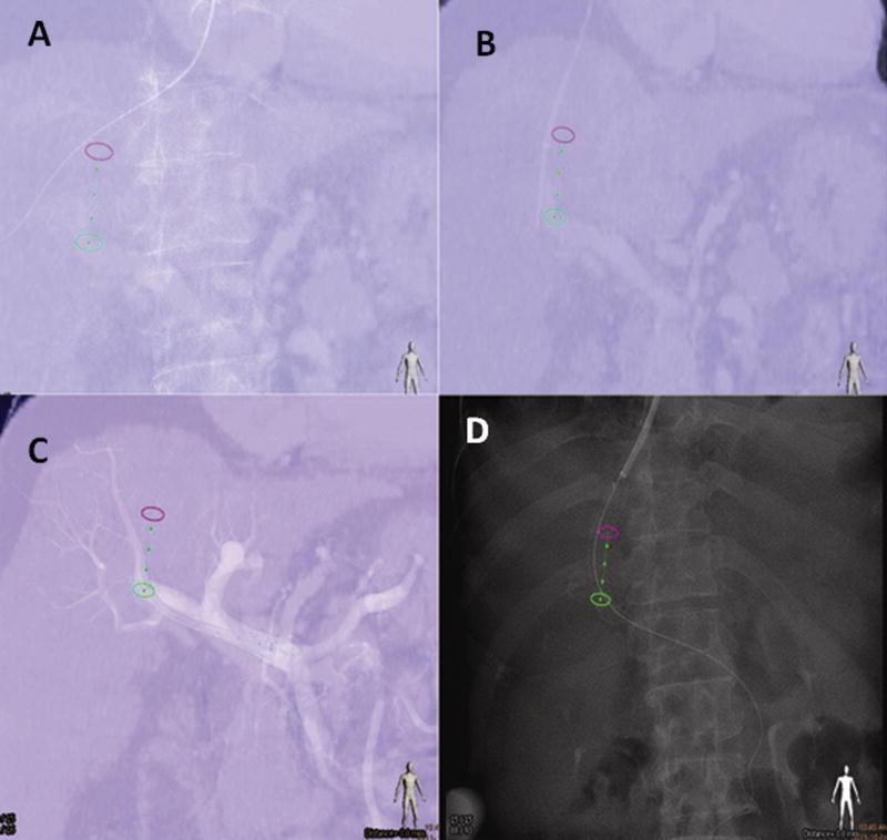
Several other case series detail the use of 3D roadmap, which provides an overlay of CT landmarks on regular DSA, to enable successful completion of challenging cases (such as percutaneous closure of an atrial septal defect or catheterization of a graft in a patient with challenging surgically distorted anatomy and history of failed catheterization attempt) 39. CBCT-based navigation may facilitate angle selection during translumbar central venous catheter placement, notorious for kinking due to the IVC access angle24 or transjugular intrahepatic portosystemic shunt placement(figure 6).
Figure 6.
A transjugular intra-hepatic portosystemic shunt (TIPS) procedure using the portal vein phase of a CT to guide catheterization of the portal vein with XperGuide needle path (Philips Healthcare Systems, Best NL). Figure 6a demonstrates guidewire positioned in the right hepatic vein and projected over of the needle path (green line flanked by green and pink circles). Figure 6b shows the needle positoned at the level of the right portal vein (note the small position shift due to the liver motion during breathing). An angiographic control after crossing with the 10 French long introducer is seen in figure 6c. Figure 6d delineates imaging following deployment of the covered stent between the right hepatic vein and the right portal vein.. Note the alignment of the stent relative to the planned needle path.
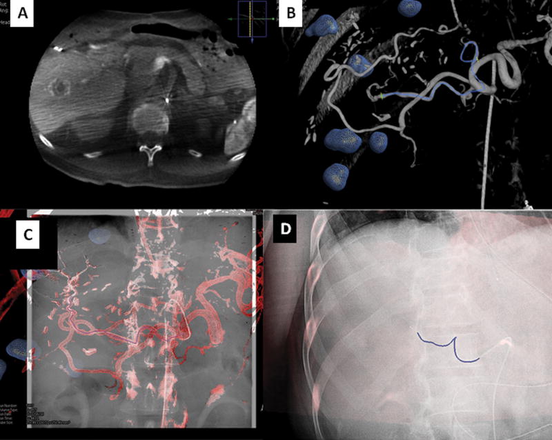
Deschamps et al. 40 published in 2010 their experience with a CBCT treatment planning software on 18 patients undergoing 25 chemoembolizations. The authors examined tumor delineation and feeding vessel segmentation using a regular angiogram, the 3D data set of CBCT, and the CBCT treatment planning software. They concluded that the treatment planning software was significantly more sensitive to determine the vascularity of a tumor and inter-observer correlation was significantly higher with its use making results more reproducible. The authors did not use CBCT navigation for catheter positioning which was performed with conventional angiographic techniques however the CBCT software was used for “embolization planning” meaning that it was used to pre-determine the number and locations of feeding vessels. CBCT navigation for catheter positioning may be helpful in reducing contrast and radiation of “roadmaps/ fluorofades” for catheter position confirmation (figure 7).
Figure 7.
Vascular application of CBCT: Figure 7a demonstrated a dual phase CBCT of the liver in a patient with metastatic colorectal carcinoma. The tumors are segmented in the same fashion as with the ablation platform (blue spheres). Tumor vessel supply may be segmented manually or automatically (figure 7b–c). The 3D roadmap can be superimposed on real-time fluoroscopy to navigate to the target vessel (blue line flanked by green crosses). It is possible to display the entire 3D roadmap or simply the vessel path (figure 7d). This 3D roadmap adjusts with table motion, change of C-arm position, and image magnification.
Bronchoscopy
EM tracking during bronchoscopy has been documented as safe and beneficial for peripheral small lesions improving diagnosis in some settings from 35% to 60–70%41,42. However most of the studies are retrospective case series 43. Schwartz et al. found a diagnostic yield with electromagnetic guided biopsies of 69% 42. Gildea et al. prospectively examined the diagnostic yield of EM tracked bronchoscopy in 60 patients. The target was reached in 100% of cases with diagnostic tissue obtained in 74% of peripheral lesions and 100% of peripheral lymph nodes sampled44. More than half the lesions were less than 2 cm in size. Several EM bronchoscopy systems are commercially available with flexible tracked instruments 41. CBCT platforms are also being investigated as reference imaging to enable tracked bronchoscopy 41.
Prostate
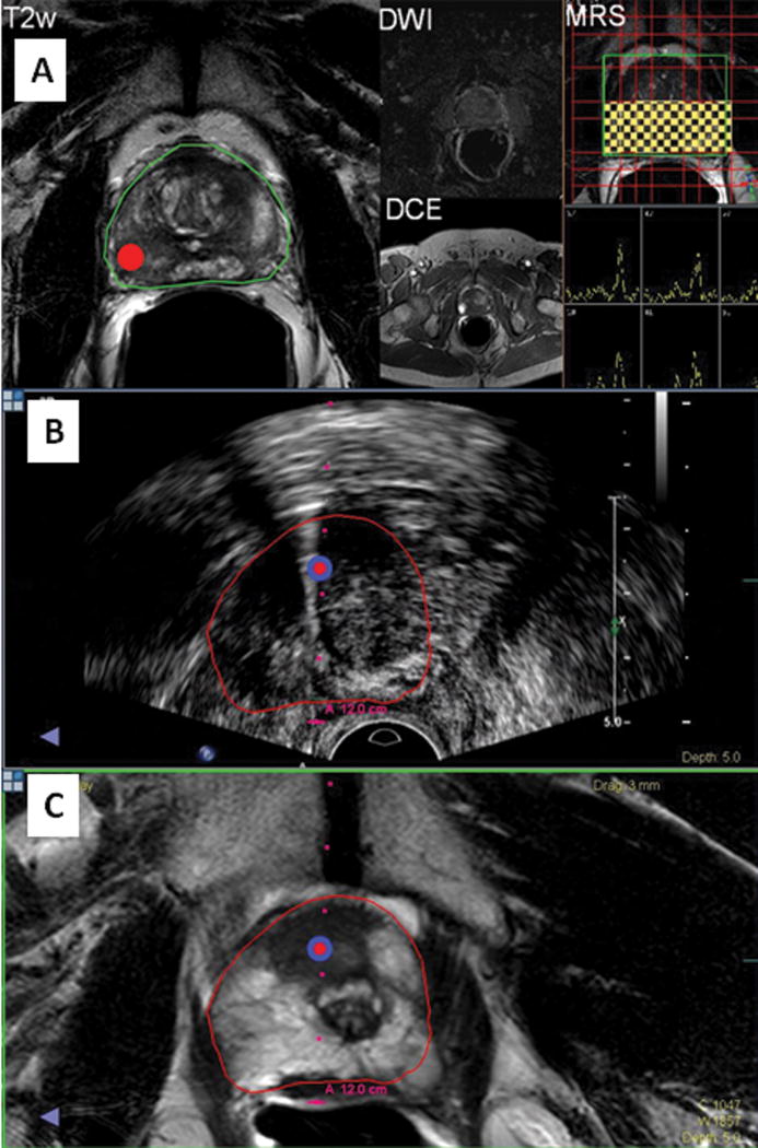
Electromagnetic tracking of transrectal ultrasound enables the use of MRI imaging outside of the MRI for fusion-guided targeted prostate biopsies, using both the real time feedback of ultrasound, and the tissue characterization of multi-parametric MRI (including MR Spectroscopy, diffusion weighted imaging, and dynamic contrast enhanced MRI45,46,47. The MRI images are used to select and navigate biopsies to targets identified on MRI, after co-registration of the ultrasound to MRI with motion compensation. Such fusion-targeted prostate biopsies can be performed in the office setting, and markedly improve the detection yield of prostate biopsies over standard random transrectal ultrasound guided biopsies (figure 8). In patients with suspicious lesions identified on MRI, the targeted fusion biopsy yields approximately double the positive biopsy rate of standard random biopsies47. In addition, the technology can be used to map the location of biopsy for subsequent repeat biopsy or focal therapy, which may be important in patients with low Gleason scores undergoing watchful waiting or surveillance. 46.
Figure 8.
EM tracked prostate biopsy. Figure 8a (upper): The target is identified on MRI (red dot), based upon multi-parametric MRI (MR spectroscopy, T2, diffusion weighting, and dynamic contrast enhanced MRI). Figure 8b and c (middle and lower): the intra-procedural ultrasound is registered in the virtual space and corresponding anatomic location in three-dimensional space on the MRI is co-displayed. The target is marked on the ultrasound and the MRI images and needle location is displayed in relation to the MRI-defined target.
Future Directions
The safety and feasibility of multimodality image fusion navigation techniques have been demonstrated and their clinical efficacy and indications are being defined. Image fusion navigation while first utilized in the operating room for surgical navigation, is currently used in endoscopic, bronchoscopic, urologic and percutaneous non-vascular and vascular interventional procedures.
These technologies are especially useful in approaching lesions that are only visualized with certain modalities or phases i.e. PET-CT, MRI or arterial phase CT only. Navigation technologies are also potentially very useful in complex or large ablations that require multiple overlapping ablation locations. The ablation planning software can aid the physician to depict not only the target tissue, but also superimposed planned ablation zones. This could enable or facilitate more complete tumor coverage and aid the repositioning of subsequent needles to predefined tumor tissue (or tissue targets at risk for under-treatment) 8. Cone beam CT-based techniques for catheter and needle based navigation have also been developed in recent years and provide some similar functionality, with some key differences. In the near future, registration and throughput is expected to become faster and more integrated. Indeed, combinations of navigation technologies are becoming more widespread in minimally invasive medicine, as is the use of pre-procedural imaging during procedures performed by non-radiology disciplines. This multidisciplinary approach is often most effective with an active role-played by the interventional radiologist. As these technologies evolve, their application to more complex procedures will better define their exact clinical roles and utilities. It is possible that multimodality imaging will lead to improved use of multi-parametric tissue characterization (where layers of three-dimensional data are matched to each other). This could further guide interventional therapies, where navigation systems will provide the registration tools and report the location for cellular imaging devices or microscope / needles. Fusion guided biopsies will become not only a tool for drug discovery, but also a vital tool for establishing specific drug combinations to which a specific tumor will respond. As the role of the interventional radiologist expands within oncology, PET-guided ablation or other multimodality fusion navigation tools could help refine the term “molecular interventions” and further personalize the minimally invasive care of cancer patients.
Table 1.
Comparison of the main features of various navigation systems
| EM tracking | CBCT Navigation | Optical Tracking | |
|---|---|---|---|
| Equipment | EM field Generator, Workstation, Devices | Workstation integrated in angiography suite | Infrared camera, Workstation, Devices, |
| FOV | 50cm or 70cm | 23cm or 46cm | 120–200cm |
| Disposables | Devices, Fiducial patches | None | Devices, fiducials |
| Motion Correction | Dynamic referencing for respiratory and patient motion, Respiratory gating | Table tracking, dynamic monitoring of fluoroscopy overlay over 3D dataset, manual correction | Dynamic referencing for patient motion |
| Real Time Imaging | Ultrasound | Fluoroscopy | Ultrasound |
| Radiation | None | Fluoroscopy | None |
| Vascular applications | Minimal so far | 3D (MR/CT) roadmap | None |
Acknowledgments
We would like to acknowledge Peter Pinto, Peter Choyke, Baris Turkbey, Julie Locklin, Stacey Gates for their contributions towards prostate fusion biopsy section. We would also like to acknowledge Ankur Kapoor for contributions on optical tracking section.
Footnotes
Nadine Abi-Jaoudeh M.D., Aradhana M. Venkatesan M.D., Elliot Levy M.D., Bradford J. Wood M.D. have no conflicts of interest however the National Institutes of Health has a Cooperative Research and Development Agreement with Philips Healthcare Company. Jochen Kruecker PhD. is a salaried employee of Royal Philips Electronics. Samuel Kadoury PhD. and Hicham Kobeiter M.D. have no conflicts of interests.
Disclosures:
Supported in part by NIH Center for Interventional Oncology & NIH intramural research program. This work is also supported by a collaborative research and development agreements (NIH and Philips Healthcare). The content of this publication does not necessarily reflect the views or policies of the Department of Health and Human Services, nor does mention of trade names, commercial products, or organizations imply endorsement by the U.S. Government.
References
- 1.Crommelin DJ, Storm G, Luijten P. ‘Personalized medicine’ through ‘personalized medicines’: Time to integrate advanced, non-invasive imaging approaches and smart drug delivery systems. Int J Pharm. 2011 doi: 10.1016/j.ijpharm.2011.02.010. [DOI] [PubMed] [Google Scholar]
- 2.Witte MH. Translational/personalized medicine, pharmaco/surgico/radiogenomics, lymphatic spread of cancer, and medical ignoromes. Journal of surgical oncology. 2011;103:501–7. doi: 10.1002/jso.21738. [DOI] [PMC free article] [PubMed] [Google Scholar]
- 3.Tandon P, Farahani K. NCI Image-Guided Drug Delivery Summit. Cancer research. 2011;71:314–7. doi: 10.1158/0008-5472.CAN-10-2629. [DOI] [PMC free article] [PubMed] [Google Scholar]
- 4.Venkatesan AM, Kadoury S, Abi-Jaoudeh N, et al. Real-time FDG PET guidance during biopsies and radiofrequency ablation using multimodality fusion with electromagnetic navigation. Radiology. 2011;260:848–56. doi: 10.1148/radiol.11101985. [DOI] [PMC free article] [PubMed] [Google Scholar]
- 5.Krucker J, Xu S, Glossop N, et al. Electromagnetic tracking for thermal ablation and biopsy guidance: clinical evaluation of spatial accuracy. Journal of vascular and interventional radiology : JVIR. 2007;18:1141–50. doi: 10.1016/j.jvir.2007.06.014. [DOI] [PMC free article] [PubMed] [Google Scholar]
- 6.Krucker J, Xu S, Venkatesan A, et al. Clinical utility of real-time fusion guidance for biopsy and ablation. Journal of vascular and interventional radiology : JVIR. 2011;22:515–24. doi: 10.1016/j.jvir.2010.10.033. [DOI] [PMC free article] [PubMed] [Google Scholar]
- 7.Giesel FL, Mehndiratta A, Locklin J, et al. Image fusion using CT, MRI and PET for treatment planning, navigation and follow up in percutaneous RFA. Exp Oncol. 2009;31:106–14. [PMC free article] [PubMed] [Google Scholar]
- 8.Wood BJ, Kruecker J, Abi-Jaoudeh N, et al. Navigation systems for ablation. J Vasc Interv Radiol. 21:S257–63. doi: 10.1016/j.jvir.2010.05.003. [DOI] [PMC free article] [PubMed] [Google Scholar]
- 9.Wood BJ, Zhang H, Durrani A, et al. Navigation with electromagnetic tracking for interventional radiology procedures: a feasibility study. J Vasc Interv Radiol. 2005;16:493–505. doi: 10.1097/01.RVI.0000148827.62296.B4. [DOI] [PMC free article] [PubMed] [Google Scholar]
- 10.Abi-Jaoudeh N, Glossop N, Dake M, et al. Electromagnetic navigation for thoracic aortic stent-graft deployment: a pilot study in swine. J Vasc Interv Radiol. 2010;21:888–95. doi: 10.1016/j.jvir.2009.12.402. [DOI] [PMC free article] [PubMed] [Google Scholar]
- 11.Hassfeld S, Muhling J, Zoller J. Intraoperative navigation in oral and maxillofacial surgery. Int J Oral Maxillofac Surg. 1995;24:111–9. doi: 10.1016/s0901-5027(05)80871-9. [DOI] [PubMed] [Google Scholar]
- 12.Phee SJ, Yang K. Interventional navigation systems for treatment of unresectable liver tumor. Med Biol Eng Comput. 2010;48:103–11. doi: 10.1007/s11517-009-0568-3. [DOI] [PubMed] [Google Scholar]
- 13.Racadio JM, Babic D, Homan R, et al. Live 3D guidance in the interventional radiology suite. Ajr. 2007;189:W357–64. doi: 10.2214/AJR.07.2469. [DOI] [PubMed] [Google Scholar]
- 14.Appelbaum L, Sosna J, Nissenbaum Y, Benshtein A, Goldberg SN. Electromagnetic navigation system for CT-guided biopsy of small lesions. Ajr. 2011;196:1194–200. doi: 10.2214/AJR.10.5151. [DOI] [PubMed] [Google Scholar]
- 15.Santos RS, Gupta A, Ebright MI, et al. Electromagnetic navigation to aid radiofrequency ablation and biopsy of lung tumors. The Annals of thoracic surgery. 2010;89:265–8. doi: 10.1016/j.athoracsur.2009.06.006. [DOI] [PubMed] [Google Scholar]
- 16.Rosenow JM, Sootsman WK. Application accuracy of an electromagnetic field-based image-guided navigation system. Stereotact Funct Neurosurg. 2007;85:75–81. doi: 10.1159/000097922. [DOI] [PubMed] [Google Scholar]
- 17.Penzkofer T, Bruners P, Isfort P, et al. Free-hand CT-based electromagnetically guided interventions: Accuracy, efficiency and dose usage. Minim Invasive Ther Allied Technol. 2011;20:226–33. doi: 10.3109/13645706.2011.553256. [DOI] [PubMed] [Google Scholar]
- 18.Ricci WM, Russell TA, Kahler DM, Terrill-Grisoni L, Culley P. A comparison of optical and electromagnetic computer-assisted navigation systems for fluoroscopic targeting. J Orthop Trauma. 2008;22:190–4. doi: 10.1097/BOT.0b013e31816731c7. [DOI] [PubMed] [Google Scholar]
- 19.Rombaux P, Ledeghen S, Hamoir M, et al. Computer assisted surgery and endoscopic endonasal approach in 32 procedures. Acta Otorhinolaryngol Belg. 2003;57:131–7. [PubMed] [Google Scholar]
- 20.Anon JB. Computer-aided endoscopic sinus surgery. Laryngoscope. 1998;108:949–61. doi: 10.1097/00005537-199807000-00001. [DOI] [PubMed] [Google Scholar]
- 21.Liodakis E, Chu K, Westphal R, et al. Assessment of the accuracy of infrared and electromagnetic navigation using an industrial robot: Which factors are influencing the accuracy of navigation? J Orthop Res. 2011 doi: 10.1002/jor.21429. [DOI] [PubMed] [Google Scholar]
- 22.Ecke U, Luebben B, Maurer J, Boor S, Mann WJ. Comparison of Different Computer-Aided Surgery Systems in Skull Base Surgery. Skull Base. 2003;13:43–50. doi: 10.1055/s-2003-820556. [DOI] [PMC free article] [PubMed] [Google Scholar]
- 23.Maeda NOK, Higashihara H, et al. A novel cone-beam CT guided interventions by XperGuide: accuracy and feasibility in a phantom model. J Vasc Interv Radiol. 2008;19:S90. [Google Scholar]
- 24.Tam A, Mohamed A, Pfister M, Rohm E, Wallace MJ. C-arm Cone Beam Computed Tomographic Needle Path Overlay for Fluoroscopic-Guided Placement of Translumbar Central Venous Catheters. Cardiovascular and interventional radiology. 2009 doi: 10.1007/s00270-008-9493-3. [DOI] [PubMed] [Google Scholar]
- 25.Mohlenbruch M, Nelles M, Thomas D, et al. Cone-beam computed tomography-guided percutaneous radiologic gastrostomy. Cardiovascular and interventional radiology. 2010;33:315–20. doi: 10.1007/s00270-009-9641-4. [DOI] [PubMed] [Google Scholar]
- 26.Wilhelm KE, Rudorf H, Greschus S, et al. Cone-Beam Computed Tomography (CBCT) dacryocystography for imaging of the nasolacrimal duct system. Klin Neuroradiol. 2009;19:283–91. doi: 10.1007/s00062-009-9025-9. [DOI] [PubMed] [Google Scholar]
- 27.Braak SJ, van Strijen MJ, van Leersum M, van Es HW, van Heesewijk JP. Real-Time 3D fluoroscopy guidance during needle interventions: technique, accuracy, and feasibility. Ajr. 194:W445–51. doi: 10.2214/AJR.09.3647. [DOI] [PubMed] [Google Scholar]
- 28.Leschka SC, Babic D, El Shikh S, Wossmann C, Schumacher M, Taschner CA. C-arm cone beam computed tomography needle path overlay for image-guided procedures of the spine and pelvis. Neuroradiology. 2011 doi: 10.1007/s00234-011-0866-y. [DOI] [PubMed] [Google Scholar]
- 29.Huber J, Wegner I, Meinzer HP, et al. Multimedia article. Navigated renal access using electromagnetic tracking: an initial experience. Surg Endosc. 2011;25:1307–12. doi: 10.1007/s00464-010-1338-x. [DOI] [PubMed] [Google Scholar]
- 30.Tatli S, Gerbaudo VH, Mamede M, Tuncali K, Shyn PB, Silverman SG. Abdominal masses sampled at PET/CT-guided percutaneous biopsy: initial experience with registration of prior PET/CT images. Radiology. 2010;256:305–11. doi: 10.1148/radiol.10090931. [DOI] [PubMed] [Google Scholar]
- 31.Baegert C, Villard C, Schreck P, Soler L, Gangi A. Trajectory optimization for the planning of percutaneous radiofrequency ablation of hepatic tumors. Comput Aided Surg. 2007;12:82–90. doi: 10.3109/10929080701312000. [DOI] [PubMed] [Google Scholar]
- 32.Wood BJ, Locklin JK, Viswanathan A, et al. Technologies for guidance of radiofrequency ablation in the multimodality interventional suite of the future. J Vasc Interv Radiol. 2007;18:9–24. doi: 10.1016/j.jvir.2006.10.013. [DOI] [PMC free article] [PubMed] [Google Scholar]
- 33.McCreedy ES, Cheng R, Hemler PF, Viswanathan A, Wood BJ, McAuliffe MJ. Radio frequency ablation registration, segmentation, and fusion tool. IEEE Trans Inf Technol Biomed. 2006;10:490–6. doi: 10.1109/titb.2006.872076. [DOI] [PMC free article] [PubMed] [Google Scholar]
- 34.Spelle L, Ruijters D, Babic D, et al. First clinical experience in applying XperGuide in embolization of jugular paragangliomas by direct intratumoral puncture. International journal of computer assisted radiology and surgery. 2009;4:527–33. doi: 10.1007/s11548-009-0370-6. [DOI] [PubMed] [Google Scholar]
- 35.Girard EE, Al-Ahmad A, Rosenberg J, et al. Contrast-enhanced C-arm CT evaluation of radiofrequency ablation lesions in the left ventricle. JACC Cardiovasc Imaging. 2011;4:259–68. doi: 10.1016/j.jcmg.2010.11.019. [DOI] [PMC free article] [PubMed] [Google Scholar]
- 36.Manstad-Hulaas F, Ommedal S, Tangen GA, Aadahl P, Hernes TN. Side-branched AAA stent graft insertion using navigation technology: a phantom study. European surgical research Europaische chirurgische Forschung. 2007;39:364–71. doi: 10.1159/000106512. [DOI] [PubMed] [Google Scholar]
- 37.Dijkstra ML, Eagleton MJ, Greenberg RK, Mastracci T, Hernandez A. Intraoperative C-arm cone-beam computed tomography in fenestrated/branched aortic endografting. J Vasc Surg. 2011;53:583–90. doi: 10.1016/j.jvs.2010.09.039. [DOI] [PubMed] [Google Scholar]
- 38.Kobeiter H, Nahum J, Becquemin JP. Zero-contrast thoracic endovascular aortic repair using image fusion. Circulation. 2011;124:e280–2. doi: 10.1161/CIRCULATIONAHA.110.014118. [DOI] [PubMed] [Google Scholar]
- 39.Garcia JA, Bhakta S, Kay J, et al. On-line multi-slice computed tomography interactive overlay with conventional X-ray: a new and advanced imaging fusion concept. International journal of cardiology. 2009;133:e101–5. doi: 10.1016/j.ijcard.2007.11.049. [DOI] [PubMed] [Google Scholar]
- 40.Deschamps F, Solomon SB, Thornton RH, et al. Computed Analysis of Three-Dimensional Cone-Beam Computed Tomography Angiography for Determination of Tumor-Feeding Vessels During Chemoembolization of Liver Tumor: A Pilot Study. Cardiovascular and interventional radiology. 2010 doi: 10.1007/s00270-010-9846-6. [DOI] [PMC free article] [PubMed] [Google Scholar]
- 41.Leira HO, Amundsen T, Tangen GA, Bo LE, Manstad-Hulaas F, Lango T. A novel research platform for electromagnetic navigated bronchoscopy using cone beam CT imaging and an animal model. Minim Invasive Ther Allied Technol. 2011;20:30–41. doi: 10.3109/13645706.2010.518747. [DOI] [PubMed] [Google Scholar]
- 42.Schwarz Y, Greif J, Becker HD, Ernst A, Mehta A. Real-time electromagnetic navigation bronchoscopy to peripheral lung lesions using overlaid CT images: the first human study. Chest. 2006;129:988–94. doi: 10.1378/chest.129.4.988. [DOI] [PubMed] [Google Scholar]
- 43.Bechara R, Parks C, Ernst A. Electromagnetic navigation bronchoscopy. Future Oncol. 2011;7:31–6. doi: 10.2217/fon.10.161. [DOI] [PubMed] [Google Scholar]
- 44.Gildea TR, Mazzone PJ, Karnak D, Meziane M, Mehta AC. Electromagnetic navigation diagnostic bronchoscopy: a prospective study. Am J Respir Crit Care Med. 2006;174:982–9. doi: 10.1164/rccm.200603-344OC. [DOI] [PMC free article] [PubMed] [Google Scholar]
- 45.Turkbey B, Mani H, Shah V, et al. Multiparametric 3T prostate magnetic resonance imaging to detect cancer: histopathological correlation using prostatectomy specimens processed in customized magnetic resonance imaging based molds. The Journal of urology. 2011;186:1818–24. doi: 10.1016/j.juro.2011.07.013. [DOI] [PMC free article] [PubMed] [Google Scholar]
- 46.Xu S, Kruecker J, Turkbey B, et al. Real-time MRI-TRUS fusion for guidance of targeted prostate biopsies. Computer aided surgery : official journal of the International Society for Computer Aided Surgery. 2008;13:255–64. doi: 10.1080/10929080802364645. [DOI] [PMC free article] [PubMed] [Google Scholar]
- 47.Pinto PA, Chung PH, Rastinehad AR, et al. Magnetic resonance imaging/ultrasound fusion guided prostate biopsy improves cancer detection following transrectal ultrasound biopsy and correlates with multiparametric magnetic resonance imaging. The Journal of urology. 2011;186:1281–5. doi: 10.1016/j.juro.2011.05.078. [DOI] [PMC free article] [PubMed] [Google Scholar]


