Abstract
The wound-healing assay is an easy and economical way to quantify cell migration under diverse stimuli. Traditional assays such as scratch assays and barrier assays are widely and commonly used, but neither of them can represent the complicated condition when a wound occurs. It has been suggested that wound-healing is related to electric fields, which were found to regulate wound re-epithelialization. As a wound occurs, the disruption of epithelial barrier short-circuits the trans-epithelial potential and then a lateral endogenous electric field is created. This field has been proved invitro as an important cue for guiding the migration of fibroblasts, macrophages, and keratinocytes, a phenomenon termed electrotaxis or galvanotaxis. In this paper, we report a microfluidic electrical-stimulated wound-healing chip (ESWHC) integrating electric field with a modified barrier assay. This chip was used to study the migration of fibroblasts under different conditions such as serum, electric field, and wound-healing-promoting drugs. We successfully demonstrate the feasibility of ESWHC to effectively and quantitatively study cell migration during wound-healing process, and therefore this chip could be useful in drug discovery and drug safety tests.
INTRODUCTION
A skin wound is defined as a break of epithelial layer of the skin,1 and the disruption may extend to deeper layers such as the dermis, subcutaneous fat, and muscle. After du Bois-Reymond first discovered that an injured finger is electrically positive compared to an intact one in 1890, it has been suggested that the electric current may be related to wound-healing. Later, Barker et al. reported that in the normal skin of a cavy, a difference in electric potential between the epidermis and the dermis was detected and measured to range from 30 to 100 mV.2 When a wound occurred, a lateral voltage gradient of about 100–200 mV/mm was generated nearby. Based on the findings of Reymond and Barker, exogenous electrical stimuli have been shown to accelerate the healing of wounds in both animal and human models.3, 4, 5, 6, 7, 8, 9 In recent years, using electric stimuli with very low amplitudes and frequencies has become the current trend in wound-healing applications. Depending on the polarity of the electrode put onto the wound site, the effect of electric field could be different. The cathodal direct-current stimulation was shown to successfully treat infection, inflammation, and granulation, while the anodal stimulation aids autolysis and re-epithelialization.
The generation of endogenous electric current can trace back to the breakup of trans-epithelial potentials (TEPs). The epithelium of the epidermis acts as a barrier between the negative charges on the surface and the positive charges inside. This so-called TEPs results from the unbalanced distribution of ion channels of Na+, K+, and Na+/K+ ATPase. The net movement of Na+ flow generates a voltage difference across the epidermis.10, 11 Once an injury occurred, the resistance of the wound site becomes lower than that of the normal skin. As a result, a vertical electric current within the layer between epidermis and dermis is induced. This electric current then flows back to the stratum of epidermis to create the endogenous electric field. An illustrative figure is shown later.
To better understand the mechanism and effects of endogenous electric field and exogenous electrical stimuli on wounds and wound-healing, many invitro studies have been done to reveal cellular behaviors in response to electrical stimuli. It has been shown that several cells including macrophages, keratinocytes, and epidermal cells could migrate and/or re-orientate under the presence of direct current (dc) electric field (EF).12, 13, 14, 15, 16, 17, 18, 19 The directional migration of adherent cells responding to an applied dcEF is termed as electrotaxis or galvanotaxis. In recent years, there have been several reports on utilizing microfluidic devices for electrotaxis studies.20, 21, 22, 23, 24, 25, 26, 27, 28, 29 Electrotaxis is suggested to be crucial to physiological tissue development and homeostasis such as wound-healing, cancer metastasis, inflammation, cell growth, and differentiation.30, 31, 32 Wound-healing assay is the commonest method to study directional cell migration because it is economical, simple, quantitative, and able to modify experimental conditions for different purposes. The scratch wound-healing assay and the barrier wound-healing assay are two types of wound-healing assays been widely and commonly used.33, 34 The scratch wound-healing assay has many advantages such as (1) it can be conducted in any substrate, (2) cells move in a certain direction (to close the wound), and (3) the morphology and migration of cells can be observed and recorded to calculate the displacement and velocity. However, using tips to create wounds makes the size and shape of the gap difficult to control within a given experiment. Furthermore, scratching may damage the coating on surface and cause incorrect results. In contrast, the barrier wound-healing assay is more suitable for cell migration studies because it maintains surface integrity using a stopper to keep cells away from wounding area. It has been shown that this method gave similar wound-healing responses compared to the scratch wound-healing assay.35, 36, 37
Several groups have developed experimental platforms combining wound-healing assays and electrical stimuli, but all failed to represent the actual condition of an invivo wound.38 Their designs did not really illustrate the endogenous electric field occurring in the wound site. In this study, a modified barrier wound-healing assay integrated into a microfluidic chip was used to study wound-healing under electrical stimuli. This microfluidic, electrical-stimulated wound-healing chip (ESWHC) provided an invitro platform best mimicking the invivo micro-environment of a wound. NIH 3T3 fibroblasts were cultured inside the ESWHC to serve as model cells for studying the dependence of wound-healing on serum and electric field. Moreover, the effect of β-lapachone, a chemical known to promote the proliferation of fibroblasts, on wound-healing was studied. This ESWHC is applicable as a drug-screening device to investigate the effect of electric field on potential wound-healing drugs.
MATERIALS AND METHODS
System for wound-healing study
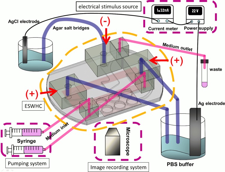
Fig. 1 shows the configuration of the entire system. The system consists of an ESWHC, an electrical stimulus source, a thermal control system (not shown in the figure), a pumping system, and an image recording system. The electrical stimulus source includes a dc power supply (GPC-3030DQ, Instek), a multimeter (189, Fluke), and two pieces of Ag/AgCl electrodes. Ag/AgCl electrodes can prevent the generation of pH gradient which is usually observed in platinum electrodes.39 Because it was reported that using Ag/AgCl might cause tissue necrosis even in the absence of an electric current,40, 41 agar salt bridges (1.5% agar dissolved in phosphate buffered saline (PBS)) were adopted to protect cells from contamination. The thermal control system consists of a transparent heater plate made of indium tin oxide glass (ITO glass, Part No. 300739, Merck), a proportional-integral-derivative (PID) controller (TTM-J40-R-AB, JETEC Electronics Co.), and a K-type thermocouple (TPK-02A, TECPEL) clipped between the ESWHC and the ITO heater. Through feedback signals from the thermocouple to the PID controller, the temperature on the ITO heater was controlled at 37 ± 0.5 °C by changing the voltage drop across the ITO heater. The pumping system includes two syringe pumps (NE-1000, New Era Pump Systems Inc.) and one 50 ml tube for waste collection. A digital camera (E410, Olympus) was connected to an inverted microscope (IX71, Olympus) for time-lapse imaging.
Figure 1.
System for wound-healing study. The design of the ESWHC is illustrated in Fig. 2. Electrical conduction is achieved via ion flow through agar salt bridges (cathode in the middle and anode on two sides). Medium is pumped into the chamber through two medium inlets and waste is collected through the medium outlet.
ESWHC design and fabrication
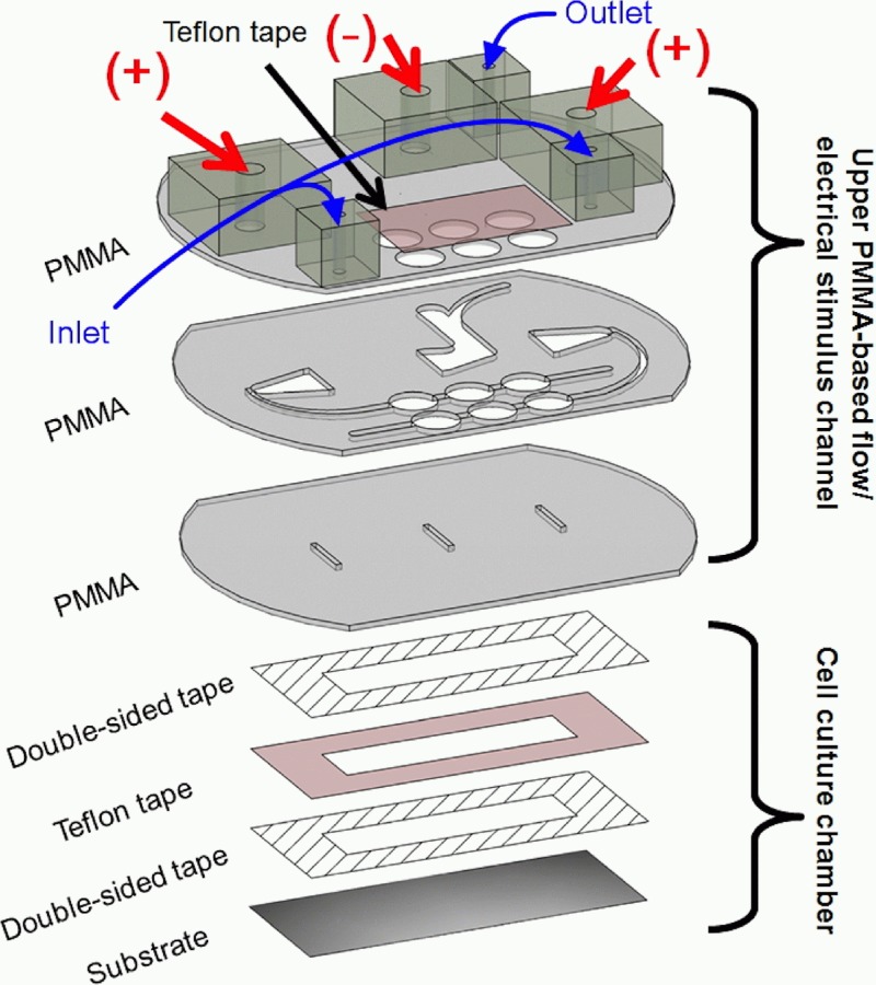
As shown in Fig. 2, the ESWHC consists of two parts, the upper PMMA-based flow/electrical stimulus channel and the bottom cell-culture chamber. Three pieces of PMMA substrates with a thickness of 1 mm were ablated using a CO2 laser scriber (ISL-II, LTT group) according to the design plotted in AutoCAD (Autodesk). Then they were bonded together by a thermal bonding unit consisting of two metal cubes and a heating component. On the top and middle PMMAs, three holes (8 mm in diameter) for each of the two inlets were created and covered with a Teflon tape for trapping bubbles pumped out from the syringes.42, 43 The top PMMA had extra six holes on it, with three (diameter = 5 mm each) glued to bigger adapters for agar salt bridges and others (diameter = 2 mm each) glued to smaller adapters for medium flow (two inlets and one outlet). The middle PMMA formed the fluidic channels for both medium flow and electrical conduction (via ion flow). The bottom PMMA had three slits on it for both medium and ion flowing into the cell-culture chamber underneath. The middle slit was used as the cathode while the other two served as the anode. For the cell-culture chamber, as shown in the lower part of Fig. 2, a Teflon tape (ASF-110, Chukoh Ltd.) and two double-sided tapes (8018, 3M) were cut by laser ablation and assembled together to form the chamber having a total thickness of 0.32 mm. Then the chamber was attached to the substrate, a tissue culture poly-styrene (TCPS) dish (430167, Corning), via one double-sided tape. To form the barrier, a piece of tape (Scotch® MagicTM Tape 810, 3M) with a width of 0.6 mm was attached to the center of the cell-culture chamber (see Fig. S2 in supplementary material42). The whole assembly process was done inside a cell-culture hood and all materials were UV sterilized.
Figure 2.
Design of the ESWHC. The top and middle PMMAs have six holes for trapping bubbles. The middle PMMA creates channels for medium and ion flowing into the cell-culture chamber underneath through three slits in the bottom PMMA. The cell-culture chamber is formed by attaching a Teflon tape and two double-sided tapes (total thickness = 0.32 mm) to a tissue culture poly-styrene (TCPS) dish.
Flow field simulation, electric field simulation, calculation, and measurement
Numerical simulations of flow and electric field were performed using commercial CFD-ACE+ suite applications (CFD-GEOM, CFD-ACE, and CFD-VIEW) (ESI Group) with flow and electric modules adopted. The electrical conductivity and viscosity of the medium were set as 1.38 Ω−1 m−1 and 0.00078 kg m−1s−1, respectively. The flow velocity was set at 5.67 × 10⁻⁷ m/s as the pumping rate set at 0.4 ml/h. To decide the dc needed to generate a desired EF inside the chip, a calculation was done based on Ohm's law. The strength of electric field through a bulk material is E = I/σAeff, where I is the electric current flowing across the material, σ is the conductivity of the material, and Aeff is the effective cross-sectional area of the material. In the present system, σ = 1.38 Ω−1m−1 and Aeff = 3.2 mm2, which results in an EF of I (mA) × 226.4 in a unit of mV/mm. Due to the design of the ESWHC, the input electric current was divided into two pathways. Therefore, to produce a desired EF of 150 mV/mm, an applied dc of 1.32 mA is required. The EF profile inside the chip was measured by Dermacorder (BioElectroMed Corp.) which is a noninvasive instrument for measuring the electric voltage on certain surfaces. This device has been applied to image the distribution of EF around skin wounds in both mice and humans.44 Its basic principle is applying different voltages to a vibrational probe and then measuring the capacitance between the probe and the unknown surface. Once the capacitance is zero, the voltage of the unknown is determined to be equal to that of the probe. This probe scans over the surface of interest so that the EF profile is acquired.
Cell preparation
Fibroblast cell line NIH 3T3 was purchased from Bioresource Collection and Research Center (BCRC), Taiwan. A complete medium composed of Dulbecco's modified Eagle medium (DMEM, Gibco) and 10% fetal bovine serum (FBS, Invitrogen) was used. Cells were incubated in TCPS flasks (Corning) in 5% CO2 at 37 °C before seeding into the cell culture chamber.
β-lapachone
β-lapachone (3,4-dihydro-2,2-dimethyl-2H-naphthol[1,2-b] pyran-5,6-dione), a derivative of naturally occurring lapachol, was reported to exhibit various pharmacological properties, such as anti-bacterial, anti-fungal, anti-plasmodial, anti-inflammatory, anti-angiogenic, anti-cancer, anti-metastatic, and anti-invasive, at different concentrations and conditions.45, 46, 47, 48, 49, 50, 51, 52 It also has a positive effect on wound-healing since low concentration of β-lapachone promoted the proliferation of keratinocytes, fibroblasts, and endothelial cells, as well as accelerated the migration of fibroblasts and EAhy926 cells through different mitogen-activated protein kinase (MAPK) signaling pathways.53 In this study, it was used as a sample drug to investigate its effects on wound-healing and also to test the applicability of the ESWHC.
Wound-healing experiment
150 μl cell suspension at a density of 1 × 10⁶ cell/ml was pipetted into the cell-culture chamber and then the chamber was incubated in 5% CO2 at 37 °C for 3 h. Once the cells adhered to the TSPC dish, the tape-made barrier was torn off to form the wound site. Then the chamber was attached to the PMMA-based flow/electrical stimulus channel via the upper double-sided tape. The inlet/outlet tubes and agar salt bridges were connected to desired adapters of the ESWHC. DMEM with or without serum was pumped into the chip at a velocity of 0.4 ml/h during the experiment. For the wound-healing study, the ESWHC was mounted on top of the transparent ITO heater, and the chip-heater unit was clipped onto a xy stage of the inverted microscope for cell observation using a 10× objective. Then agar bridges were placed in beakers filled with PBS, where Ag/AgCl electrodes were connected to the dc power supply. The middle slit of the ESWHC was linked to AgCl electrode as the cathode while the outside two slits were linked to Ag electrode as the anodes.
Data analysis
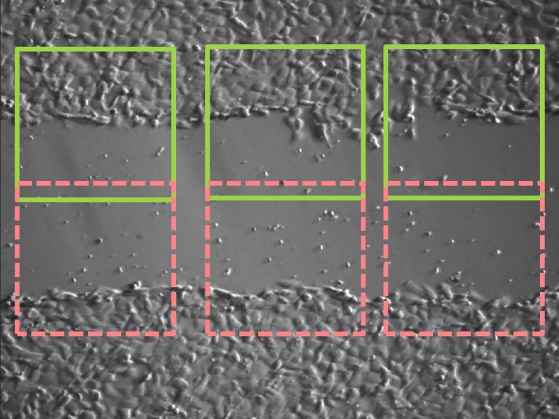
To observe wound-healing process, time-lapse images were taken at an interval of 5 min for 2 h. Images were further analyzed using imagej which is a free java-based software developed by the National Institute of Health (NIH). As shown in Fig. 3, for each image, six regions of interest (ROIs) were picked to determine the population of cells within. The wound-healing rate in a unit of μm/h is defined as the progressing rate of the area covered with cells divided by the length of rectangular ROI. For each experimental condition, three independent runs were performed to get the standard error of the mean (SEM). Statistical differences between experimental and control groups were assessed by unpaired Student's t-test.
Figure 3.
Regions of analysis in one image.
RESULTS AND DISCUSSION
Flow field and electric field simulation
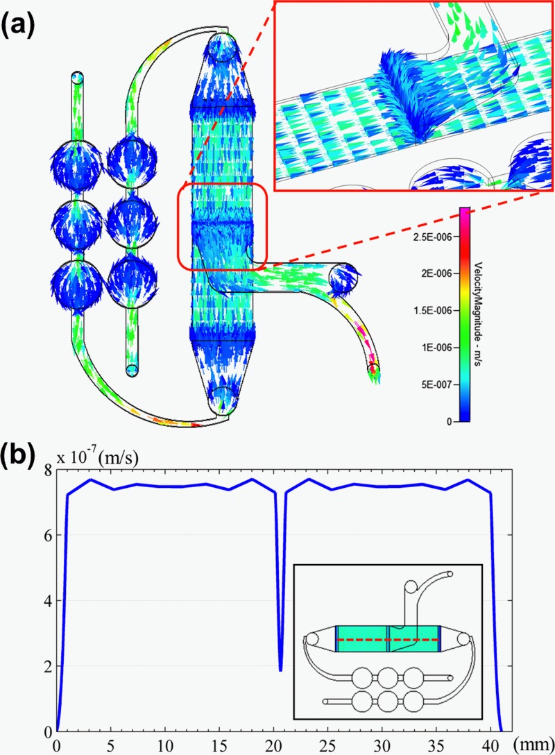
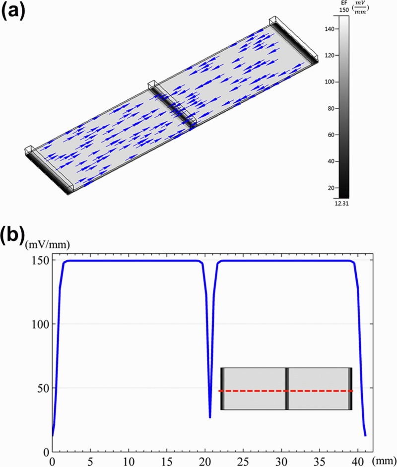
Fig. 4a shows the numerical simulation of flow field distribution in the ESWHC, where the direction and strength of the field were represented by color vectors. Fig. 4b is the profile of flow velocity horizontally across the chip at a height of about 20 μm. By the simulation, nearly homogeneous flow fields were observed in the cell-culture region except for a sudden dip in the center due to the middle slit. As the inlet velocity set at 5.67 × 10⁻⁷ m/s, the flow velocity was about 7.5 × 10⁻⁷ m/s across the cell-seeding area. Another simulation was done (data not shown) to reveal the distribution of shear stress in the chip. The shear stress across the same horizontal region was about 3.4 × 10⁻⁶ Pa with good homogeneity. This value is way smaller than a physiological threshold of 0.3 Pa to affect endothelial cells to remodel themselves.54 Fig. 5a shows the numerical simulation of electric field distribution in the ESWHC, where the direction and strength of the field were represented by arrows and gray color, respectively. The EF only exits in the path of electric current. The inset shows the endogenous current and EF when a wound occurs,55 showing the same EF directions as in our simulation. Fig. 5b shows the profile of EF across the cell-culture region at a height of about 20 μm. Again, the simulation showed a homogeneous distribution of EF in the chip, with a value of about 150 mV/mm at an input dc of 66 mA in each side. This value is close to the calculation based on Ohm's law (see Sec. 2).
Figure 4.
(a) Flow field simulation of the whole ESWHC including two medium inlets, one medium outlet, and six bubble traps. The arrow and color represent the direction and strength of the flow field, respectively. The inset shows the flow field of the wound site, where a sudden dip occurs due to the slit. (b) Profile of flow velocity across the cell-culture region (shown in red dashed line) at a height of about 20 μm.
Figure 5.
(a) Electric field simulation of the ESWHC. Only the region between two anodes is shown. The arrow represents the direction of the electric field. The inset shows the endogenous current and EF when a wound occurs.55 (b) Profile of EF across the cell-culture region (shown in red dashed line) at a height of about 20 μm.
Electric field measurement
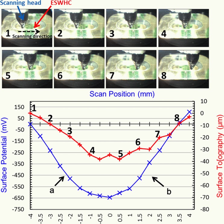
As shown in Fig. 6, the electric field inside the ESWHC was measured by Dermacorder. By moving the scanning head (with the vibrational probe on the tip of it) 8 mm horizontally across the cell-culture chamber (marked from 1 to 8), both the surface potential (in mV) and topography (in μm) were plotted against the distance. The surface topography resembled the profile of surface potential and had a variation of about 40 μm because the vibrational probe had to slightly adjust its height to better measure the capacitance between the probe and the unknown surface. The observed topographical change is insignificant (40 μm across 8 mm). The EF of a given region is the slope of the curve there. Therefore, in region “a,” the EF is about 161 mV/mm toward the center, while the EF in region “b” is about 181 mV/mm toward the center. These values are a little bit off the calculation, which is 150 mV/mm, mainly due to the presence of the bottom cover glass. The EF profile acquired here (nearly constant in two sides with a sudden dip in the center) was similar to the simulation shown in Fig. 5a. Nuccitelli et al. measured the EF of a 0.5 mm-wide lancet wound and acquired a very similar EF profile with a value of about 160 mV/mm.56 This suggests that the ESWHC provided a micro-environment closely resembling the EF near an invivo wound site.
Figure 6.
In vitro measurement of electric field inside the ESWHC using Dermacorder. Top: Images of the scanning head in different positions of the chip (8 mm scanning distance in total). Bottom: Measured surface potential (in mV) and topography (in μm) plotted against the distance.
Dependence of wound-healing rate on serum and electric field
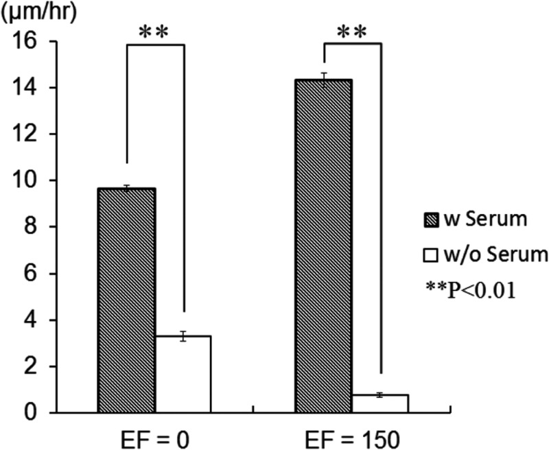
It was reported that the shape or orientation of epithelial cells and fibroblasts only changed a little bit under an EF lower than 400 mV/mm.57 FBS is known to promote cell migration in corneal epithelial cells under EF stimuli. Therefore, the presence of serum might lower the threshold of EF required for activating cells’ migration and re-orientation.38 The effect of serum on wound-healing rate was shown in Fig. 7. In the absence of EF, the wound-healing rate increased from 3.3 to 9.7 μm/h (3 times difference) with the presence of serum. This phenomenon was even more obvious when an EF was presented, where the wound-healing rate increased from 0.77 to 14 μm/h (19 times difference) with the presence of serum. This observation suggests that the migration of fibroblasts is serum-dependent. Serum can accelerate fibroblast migration, and such effect is more evident with EF presented. NIH 3T3 fibroblasts were reported to migrate toward the cathode under an EF of 400 mV/mm.58 In our ESWHC, fibroblasts migrated toward the cathode to repopulate the artificial “wound.” As shown in Fig. 7, in the presence of serum, the wound-healing rate increased from 9.7 to 14 μm/h in response to an applied EF of 150 mV/mm. This suggested that the generation of EF at the wound site (the endogenous EF) participates in promoting cell migration. Also, the applied exogenous electrical stimuli may accelerate the wound-healing process. By applying an inverted dc to the wound of an invivo newt to change the intrinsic EF, Chiang et al. tested the hypothesis that the endogenous EF is important in wound-healing process.59 It was observed that the nullified EF caused a ∼15% decrease in the rate of wound re-epithelialization. This concluded the importance of EF (intrinsic or extrinsic) in wound-healing process as well as the practicability of the ESWHC in wound-healing studies.
Figure 7.
Dependence of wound-healing rate on serum and electric field.
Dependence of wound-healing rate on β-lapachone
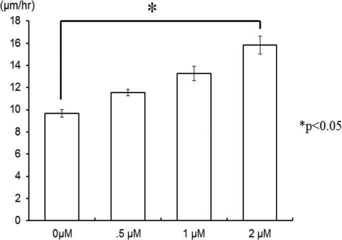
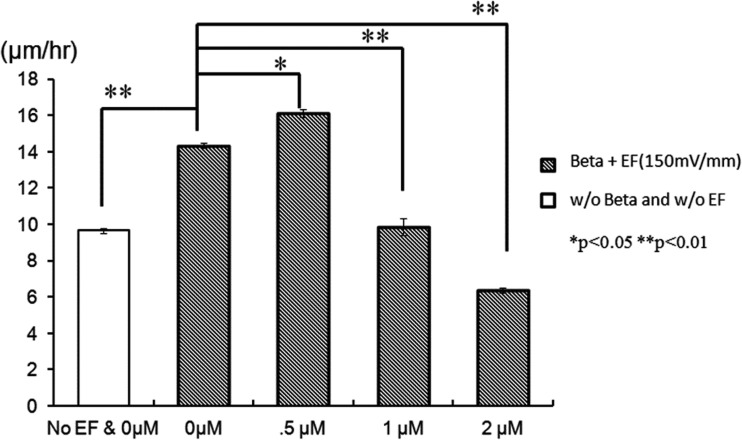
It has been reported that low concentration of β-lapachone accelerated the proliferation and migration of NIH 3T3 fibroblasts via extracellular-signal-regulated kinase (ERK) and p38 signaling pathways.53 The effect of β-lapachone alone on wound-healing rate is shown in Fig. 8. In the absence of EF, the wounding healing rate increased from 9.7 to 11.6, 13.3, and 15.8 μm/h as the concentration of β-lapachone increased from 0 to 0.5, 1, and 2 μM, respectively. This result was correspondent with the finding just described. However, as shown in Fig. 9, in the presence of EF, the effect of β-lapachone on wound-healing rate is somehow intricate. At EF = 150 mV/mm, the wound-healing rate of 0.5 μM β-lapachone is 12% faster than that without the drug (increased from 14 to 16 μm/h). However, when further increasing the concentration of β-lapachone to 1 and 2 μM, the wound-healing rate decreased instead to 9.9 and 6.4 μm/h, respectively. This suggested the coexistence of β-lapachone and EF did not yield a synergistic effect. Shiah et al. found that β-lapachone could induce the generation of reactive oxygen species (ROS) in human leukemia cells through the activation of c-Jun N-terminal kinase (JNK) pathway and then trigger the apoptosis.60 Traditionally, ROS are thought to be toxic byproducts of cellular metabolism. Recently, evidence has shown that ROS are essential and related to cell proliferation, migration, and adhesion.61, 62, 63 Also, EF was reported to increase the amount of ROS in embryonic stem cells, rat skeletal muscle cells, oral mucosa cancer cells, and NIH 3T3 fibroblasts.62, 64, 65, 66, 67, 68 Li et al. discovered that ROS played a critical role in electrotaxis of fibrosacoma cells via the activation of ERK pathway as shown schematically in the reference.69 EF induced the generation of O2− via the activation of NADPH oxidase and then activated the MAPKs, PI3Ks, and ERK pathways which were related to the rearrangement of cytoskeleton and directional migration of cells. As suggested by other research groups, low concentration of ROS promoted cell-to-cell communication and cell proliferation,70 while high concentration of ROS induced oxidative damage to cells and stopped them in the G0/G1 phase.71, 72 Therefore, it was concluded that both β-lapachone and EF generated ROS, but instead of accelerating cell migration, excessive ROS caused certain damage to cells, which in turn decreased the wound-healing rate as seen in Fig. 9. EF together with 0.5 μM β-lapachone produced sufficient ROS to accelerate cell migration, but the addition of higher concentration of β-lapachone generated excess ROS to decrease the wound-healing rate instead.
Figure 8.
Dependence of wound-healing rate on different concentrations of β-lapachone in the absence of EF.
Figure 9.
Dependence of wound-healing rate on different concentrations of β-lapachone in the presence of EF.
CONCLUSION
Exogenous and endogenous electric fields have been shown to guide and promote the migration of cells, as well as accelerate the wound-healing process. However, none of the present assays or devices can realistically resemble the EF micro-environment near the wound site. Here, we designed and fabricated the microfluidic, ESWHC which provided an invitro platform best mimicking the invivo EF distribution of a wound. NIH 3T3 fibroblasts were used as model cells to study the dependence of wound-healing rate on serum and electric field. It was found that both serum and EF increased the wound-healing rate obviously. In addition, our results showed that β-lapachone alone or low concentration of β-lapachone combined with EF increased the healing rate, but overdose of β-lapachone in the presence of EF decreased the rate instead probably due to too many ROS produced. Therefore, to test the potency and study the pharmacodynamics of potential wound-healing drugs, it is of importance to take the effect of electric field into consideration as well. This ESWHC provides an easy and fast platform for invitro drug-screening in a high-throughput manner before conducting invivo trials.
ACKNOWLEDGMENTS
This work is financially supported by the National Science Council, Taiwan (Contract No. 100-2113-M-001-014-MY3) and the Research Program on Nanoscience and Nanotechnology, Academia Sinica, Taiwan. The authors would like to thank Miss Huai-Fang Chang for help in cell culturing.
References
- Teare J. and Barrett C., Nurs. Stand 17(6), 59–60 (2002). [PubMed] [Google Scholar]
- Barker A. T., Jaffe L. F., and J. W.Vanable, Jr., Am. J. Physiol. 242(3), R358–R366 (1982). [DOI] [PubMed] [Google Scholar]
- Carley P. J. and Wainapel S. F., Arch. Phys. Med. Rehabil. 66(7), 443–446 (1985). [PubMed] [Google Scholar]
- Brown M., McDonnell M. K., and Menton D. N., Arch. Phys. Med. Rehabil. 70(8), 624–627 (1989). [PubMed] [Google Scholar]
- Kloth L. C. and McCulloch J. M., Adv. Wound Care 9(5), 42–45 (1996). [PubMed] [Google Scholar]
- Baker L. L., Chambers R., DeMuth S. K., and Villar F., Diabetes Care 20(3), 405–412 (1997). 10.2337/diacare.20.3.405 [DOI] [PubMed] [Google Scholar]
- Braddock M., Campbell C. J., and Zuder D., Int. J. Dermatol. 38(11), 808–817 (1999). 10.1046/j.1365-4362.1999.00832.x [DOI] [PubMed] [Google Scholar]
- Reger S. I., Hyodo A., Negami S., Kambic H. E., and Sahgal V., Artif. Organs 23(5), 460–462 (1999). 10.1046/j.1525-1594.1999.06365.x [DOI] [PubMed] [Google Scholar]
- Demir H., Balay H., and Kirnap M., J. Rehabil. Res. Dev. 41(2), 147–154 (2004). 10.1682/JRRD.2004.02.0147 [DOI] [PubMed] [Google Scholar]
- Nuccitelli R., Radiat. Prot. Dosim. 106(4), 375–383 (2003). 10.1093/oxfordjournals.rpd.a006375 [DOI] [PubMed] [Google Scholar]
- Nuccitelli R., Curr. Top. Dev. Biol. 58, 1–26 (2003). 10.1016/S0070-2153(03)58001-2 [DOI] [PubMed] [Google Scholar]
- Bourguignon G. J. and Bourguignon L. Y., FASEB J. 1(5), 398–402 (1987). [DOI] [PubMed] [Google Scholar]
- Cooper M. S. and Schliwa M., J. Neurosci. Res. 13(1–2), 223–244 (1985). 10.1002/jnr.490130116 [DOI] [PubMed] [Google Scholar]
- Eberhardt A., Szczypiorski P., and Korytowski G., Acta Physiol. Pol. 37(1), 41–46 (1986). [PubMed] [Google Scholar]
- Erickson C. A. and Nuccitelli R., J. Cell Biol. 98(1), 296–307 (1984). 10.1083/jcb.98.1.296 [DOI] [PMC free article] [PubMed] [Google Scholar]
- Lee R. C., Canaday D. J., and Doong H., J. Burn Care Rehabil. 14(3), 319–335 (1993). 10.1097/00004630-199305000-00003 [DOI] [PubMed] [Google Scholar]
- Nishimura K. Y., Isseroff R. R., and Nuccitelli R., J. Cell Sci. 109(Part 1), 199–207 (1996). [DOI] [PubMed] [Google Scholar]
- Orida N. and Feldman J. D., Cell Motil. 2(3), 243–255 (1982). 10.1002/cm.970020305 [DOI] [PubMed] [Google Scholar]
- Yang W. P., Onuma E. K., and Hui S. W., Exp. Cell Res. 155(1), 92–104 (1984). 10.1016/0014-4827(84)90770-5 [DOI] [PubMed] [Google Scholar]
- Sun Y. S., Peng S. W., Lin K. H., and Cheng J. Y., Biomicrofluidics 6(1), 14102–1410214 (2012). 10.1063/1.3671399 [DOI] [PMC free article] [PubMed] [Google Scholar]
- Li J., Zhu L., Zhang M., and Lin F., Biomicrofluidics 6(2), 24121–2412113 (2012). 10.1063/1.4718721 [DOI] [PMC free article] [PubMed] [Google Scholar]
- Wang C. C., Kao Y. C., Chi P. Y., Huang C. W., Lin J. Y., Chou C. F., Cheng J. Y., and Lee C. H., Lab Chip 11(4), 695–699 (2011). 10.1039/c0lc00155d [DOI] [PubMed] [Google Scholar]
- Rezai P., Salam S., Selvaganapathy P. R., and Gupta B. P., Biomicrofluidics 5(4), 44116–441169 (2011). 10.1063/1.3665224 [DOI] [PMC free article] [PubMed] [Google Scholar]
- Li J. and Lin F., Trends Cell Biol. 21(8), 489–497 (2011). 10.1016/j.tcb.2011.05.002 [DOI] [PubMed] [Google Scholar]
- Huang C. W., Chen H. Y., Yen M. H., Chen J. J., Young T. H., and Cheng J. Y., PLoS One 6(10), e25928 (2011). 10.1371/journal.pone.0025928 [DOI] [PMC free article] [PubMed] [Google Scholar]
- Rezai P., Siddiqui A., Selvaganapathy P. R., and Gupta B. P., Lab Chip 10(2), 220–226 (2010). 10.1039/b917486a [DOI] [PubMed] [Google Scholar]
- Yan X., Han J., Zhang Z., Wang J., Cheng Q., Gao K., Ni Y., and Wang Y., Bioelectromagnetics 30(1), 29–35 (2009). 10.1002/bem.20436 [DOI] [PubMed] [Google Scholar]
- Huang C. W., Cheng J. Y., Yen M. H., and Young T. H., Biosens. Bioelectron. 24(12), 3510–3516 (2009). 10.1016/j.bios.2009.05.001 [DOI] [PubMed] [Google Scholar]
- Li L., El-Hayek Y. H., Liu B., Chen Y., Gomez E., Wu X., Ning K., Chang N., Zhang L., Wang Z., Hu X., and Wan Q., Stem Cells 26(8), 2193–2200 (2008). 10.1634/stemcells.2007-1022 [DOI] [PubMed] [Google Scholar]
- Eccles S. A., Box C., and Court W., Biotechnol. Annu. Rev. 11, 391–421 (2005). 10.1016/S1387-2656(05)11013-8 [DOI] [PubMed] [Google Scholar]
- Horwitz R. and Webb D., Curr. Biol. 13(19), R756–759 (2003). 10.1016/j.cub.2003.09.014 [DOI] [PubMed] [Google Scholar]
- Zhao M., Song B., Pu J., Wada T., Reid B., Tai G., Wang F., Guo A., Walczysko P., Gu Y., Sasaki T., Suzuki A., Forrester J. V., Bourne H. R., Devreotes P. N., McCaig C. D., and Penninger J. M., Nature 442(7101), 457–460 (2006). 10.1038/nature04925 [DOI] [PubMed] [Google Scholar]
- Friedl P., Hegerfeldt Y., and Tusch M., Int. J. Dev. Biol. 48(5–6), 441–449 (2004). 10.1387/ijdb.041821pf [DOI] [PubMed] [Google Scholar]
- Yarrow J. C., Perlman Z. E., Westwood N. J., and Mitchison T. J., BMC Biotechnol. 4, 21 (2004). 10.1186/1472-6750-4-21 [DOI] [PMC free article] [PubMed] [Google Scholar]
- Block E. R., Matela A. R., SundarRaj N., Iszkula E. R., and Klarlund J. K., J. Biol. Chem. 279(23), 24307–24312 (2004). 10.1074/jbc.M401058200 [DOI] [PubMed] [Google Scholar]
- Nikolić D. L., Boettiger A. N., Bar-Sagi D., Carbeck J. D., and Shvartsman S. Y., Am. J. Physiol.: Cell Physiol. 291(1), C68–C75 (2006). 10.1152/ajpcell.00411.2005 [DOI] [PubMed] [Google Scholar]
- van Horssen R., Galjart N., Rens J. A. P., Eggermont A. M. M., and ten Hagen T. L. M., J. Cell. Biochem. 99(6), 1536–1552 (2006). 10.1002/jcb.20994 [DOI] [PubMed] [Google Scholar]
- Zhao M., Agius-Fernandez A., Forrester J. V., and McCaig C. D., J. Cell Sci. 109(6), 1405–1414 (1996). [DOI] [PubMed] [Google Scholar]
- Merrill D. R., Bikson M., and Jefferys J. G. R., J. Neurosci. Methods 141(2), 171–198 (2005). 10.1016/j.jneumeth.2004.10.020 [DOI] [PubMed] [Google Scholar]
- Stensaas S. S. and Stensaas L. J., Acta Neuropathol. 41(2), 145–155 (1978). 10.1007/BF00689766 [DOI] [PubMed] [Google Scholar]
- Babb T. L. and Kupfer W., Exp. Neurol. 86(2), 171–182 (1984). 10.1016/0014-4886(84)90179-1 [DOI] [PubMed] [Google Scholar]
- See supplementary material at http://dx.doi.org/10.1063/1.4750486 for (S1) bubble traps and (S2) barrier and cell-culture chamber.
- Cheng J. Y., Yen M. H., Kuo C. T., and Young T. H., Biomicrofluidics 2(2), 24105 (2008). 10.1063/1.2952290 [DOI] [PMC free article] [PubMed] [Google Scholar]
- Nuccitelli R., Nuccitelli P., Ramlatchan S., Sanger R., and Smith P. J. S., Wound Repair Regen. 16(3), 432–441 (2008). 10.1111/j.1524-475X.2008.00389.x [DOI] [PMC free article] [PubMed] [Google Scholar]
- Manna S. K., Gad Y. P., Mukhopadhyay A., and Aggarwal B. B., Biochem. Pharmacol. 57(7), 763–774 (1999). 10.1016/S0006-2952(98)00354-2 [DOI] [PubMed] [Google Scholar]
- Guiraud P., Steiman R., Campos-Takaki G. M., Seigle-Murandi F., and Simeon de Buochberg M., “Comparison of antibacterial and antifungal activities of lapachol and beta-lapachone,” Planta Med. 60(4), 373–374 (1994). 10.1055/s-2006-959504 [DOI] [PubMed] [Google Scholar]
- Kim S. O., Kwon J. I., Jeong Y. K., Kim G. Y., Kim N. D., and Choi Y. H., Biosci. Biotechnol. Biochem. 71(9), 2169–2176 (2007). 10.1271/bbb.70103 [DOI] [PubMed] [Google Scholar]
- Kung H. N., Chien C. L., Chau G. Y., Don M. J., Lu K. S., and Chau Y. P., J. Cell Physiol. 211(2), 522–532 (2007). 10.1002/jcp.20963 [DOI] [PubMed] [Google Scholar]
- Moon D.-O., Choi Y. H., Kim N.-D., Park Y.-M., and Kim G.-Y., Int. Immunopharmacol. 7(4), 506–514 (2007). 10.1016/j.intimp.2006.12.006 [DOI] [PubMed] [Google Scholar]
- Pardee A. B., Li Y. Z., and Li C. J., Curr. Cancer Drug Targets 2(3), 227–242 (2002). 10.2174/1568009023333854 [DOI] [PubMed] [Google Scholar]
- Pérez-Sacau E., Estévez-Braun A., Ravelo Á. G., Gutiérrez Yapu D., and Giménez Turba A., Chem. Biodiversity 2(2), 264–274 (2005). 10.1002/cbdv.200590009 [DOI] [PubMed] [Google Scholar]
- Salas C., Tapia R. A., Ciudad K., Armstrong V., Orellana M., Kemmerling U., Ferreira J., Maya J. D., and Morello A., Bioorg. Med. Chem. 16(2), 668–674 (2008). 10.1016/j.bmc.2007.10.038 [DOI] [PubMed] [Google Scholar]
- Kung H. N., Yang M. J., Chang C. F., Chau Y. P., and Lu K. S., Am. J. Physiol.: Cell Physiol. 295(4), 23 (2008). 10.1152/ajpcell.00266.2008 [DOI] [PubMed] [Google Scholar]
- Li S., Huang N. F., and Hsu S., J. Cell. Biochem. 96(6), 1110–1126 (2005). 10.1002/jcb.20614 [DOI] [PubMed] [Google Scholar]
- McCaig C. D., Song B., and Rajnicek A. M., J. Cell Sci. 122(23), 4267–4276 (2009). 10.1242/jcs.023564 [DOI] [PubMed] [Google Scholar]
- Nuccitelli R., Nuccitelli P., Li C. Y., Narsing S., Pariser D. M., and Lui K., Wound Repair Regen. 19(5), 645–655 (2011). 10.1111/j.1524-475X.2011.00723.x [DOI] [PMC free article] [PubMed] [Google Scholar]
- Soong H. K., Parkinson W. C., Bafna S., Sulik G. L., and Huang S. C., Invest. Ophthalmol. Visual Sci. 31(11), 2278–2282 (1990). [PubMed] [Google Scholar]
- Brown M. J. and Loew L. M., J. Cell Biol. 127(1), 117–128 (1994). 10.1083/jcb.127.1.117 [DOI] [PMC free article] [PubMed] [Google Scholar]
- Chiang M., E. J.Cragoe, Jr., and J. W.Vanable, Jr., Dev. Biol. 146(2), 377–385 (1991). 10.1016/0012-1606(91)90239-Y [DOI] [PubMed] [Google Scholar]
- Shiah S. G., Chuang S. E., Chau Y. P., Shen S. C., and Kuo M. L., Cancer Res. 59(2), 391–398 (1999). [PubMed] [Google Scholar]
- Connor K. M., Hempel N., Nelson K. K., Dabiri G., Gamarra A., Belarmino J., Van De Water L., Mian B. M., and Melendez J. A., Cancer Res. 67(21), 10260–10267 (2007). 10.1158/0008-5472.CAN-07-1204 [DOI] [PubMed] [Google Scholar]
- Desai S. P. and Voldman J., Integr. Biol. 3(1), 48–56 (2011). 10.1039/c0ib00067a [DOI] [PMC free article] [PubMed] [Google Scholar]
- Huo Y., Qiu W. Y., Pan Q., Yao Y. F., Xing K., and Lou M. F., Exp. Eye Res. 89(6), 876–886 (2009). 10.1016/j.exer.2009.07.012 [DOI] [PubMed] [Google Scholar]
- Chatterjee S., Browning E. A., Hong N., DeBolt K., Sorokina E. M., Liu W., Birnbaum M. J., and Fisher A. B., Am. J. Physiol. Heart Circ. Physiol. 302(1), H105–H114 (2012). 10.1152/ajpheart.00298.2011 [DOI] [PMC free article] [PubMed] [Google Scholar]
- Espinosa A., Leiva A., Peña M., Müller M., Debandi A., Hidalgo C., Angélica Carrasco M., and Jaimovich E., J. Cell Physiol. 209(2), 379–388 (2006). 10.1002/jcp.20745 [DOI] [PubMed] [Google Scholar]
- Sauer H., Rahimi G., Hescheler J., and Wartenberg M., J. Cell. Biochem. 75(4), 710–723 (1999). [DOI] [PubMed] [Google Scholar]
- Serena E., Figallo E., Tandon N., Cannizzaro C., Gerecht S., Elvassore N., and Vunjak-Novakovic G., Exp. Cell Res. 315(20), 3611–3619 (2009). 10.1016/j.yexcr.2009.08.015 [DOI] [PMC free article] [PubMed] [Google Scholar]
- Wartenberg M., Wirtz N., Grob A., Niedermeier W., Hescheler J., Peters S. C., and Sauer H., Bioelectromagnetics 29(1), 47–54 (2008). 10.1002/bem.20361 [DOI] [PubMed] [Google Scholar]
- Li F., Wang H., Li L., Huang C., Lin J., Zhu G., Chen Z., Wu N., and Feng H., Free Radic. Biol. Med. 52(9), 1888–1896 (2012). 10.1016/j.freeradbiomed.2012.02.047 [DOI] [PubMed] [Google Scholar]
- Felty Q., Xiong W. C., Sun D., Sarkar S., Singh K. P., Parkash J., and Roy D., Biochemistry 44(18), 6900–6909 (2005). 10.1021/bi047629p [DOI] [PubMed] [Google Scholar]
- Okoh V., Deoraj A., and Roy D., Biochim. Biophys. Acta 1, 115–133 (2011). 10.1016/j.bbcan.2010.10.005 [DOI] [PubMed] [Google Scholar]
- Sauer H., Wartenberg M., and Hescheler J., Cell Physiol. Biochem. 11(4), 173–186 (2001). 10.1159/000047804 [DOI] [PubMed] [Google Scholar]


