Abstract
We report on a method to fabricate biofunctionalized polyethylene glycol hydrogel microchannels with adjustable circular cross-sections. The inner channel surfaces are decorated with Au-nanoparticle arrays of tunable density. These Au-nanoparticles are functionalized with biomolecules whereas the hydrogel material provides an inert and biocompatible background. This technology provides control over flow conditions, channel curvature and biomolecule density on the channel surface. It can be applied for biophysical studies of cell-surface interactions mimicking, for example, leukocyte interactions with the endothelial lining in small vessels.
Introduction
Over the past decade, microfluidics has become a valuable tool for cell biology because it can provide control over small fluid volumes and biophysical parameters such as shear stress1. So far, most of the approaches used to fabricate microstructured systems for cell adhesion studies are based on soft lithography2. With top-down methods, the cross-section is usually limited to a rectangular geometry. However, the topography and three-dimensional shape of the substrate must be taken into account when investigating cellular interactions as cells have been shown to respond to the substrate curvature3,4,5. Moreover, curvature changes the availability of ligands and can be detected by curvature-sensing proteins6,7. Therefore, circular cross-sections of microfluidic channels could mimic natural vessels and cell-surface interactions for example in the blood stream in a more in-vivo-like manner.
Polydimethylsiloxane (PDMS) is the most commonly used material in microfluidics, but there has been only a small number of reports on approaches to fabricate cylindrical channels. One example describes the application of air pressure on PDMS-filled rectangular channels to create cylindrical channels within uncured PDMS during baking8. Such channels were used to cultivate endothelial cells, resulting in circular channels lined with an endothelial cell monolayer that could mimic natural vessels very precisely9.
Another common issue of microfluidic systems is surface functionalization as PDMS surface functionalization remains a major challenge10. Especially for biological applications, covalent and site-directed immobilization of biomolecules is desirable. Closely related to surface functionalization is the question of how many molecules a surface must present to mimic a biological interface or perform a specific task. The density and spatial presentation of adhesion sites on surfaces can have a dramatic influence on cell adhesion11. As a prominent example, adhesive interactions of circulating blood cells with the endothelium during inflammation are governed by the up- and down 5 regulation of cell surface receptor density12.
The use of PDMS in microfluidics has certain drawbacks such as the mentioned surface functionalization issues and the release of unpolymerized monomers13. Alternative materials are usually less convenient in handling, but can have advantages for specific applications. Hydrogels, for example, are promising materials for cell culture and microfluidic systems. Among them polyethylene glycol (PEG)-hydrogels are frequently used because they are biocompatible, inert, transparent and can be tailored with specific chemical groups14. They can also be replica molded to form rectangular hydrogel channels for cell culture applications15.
Hydrogels would be ideally suited for microfluidic systems with circular cross-sections of micron-sized channels/substrates. Moreover, there is a need for site-directed biofunctionalization of channel surfaces in combination with a control of biomolecule density. Therefore, we have developed a method to fabricate hydrogel channels with circular cross-section in the micron range. The inner surfaces of the hydrogel channels are decorated with Au-nanoparticles (Au-NPs) of tunable density. This nanoparticle pattern allows the functionalization of the channel surface without changing the inert hydrogel background. Such channels can be implemented into microfluidic setups to control flow conditions.
Materials and Methods
Experimental details are thoroughly described in the Electronic Supplementary Information (ESI).
Results and Discussion
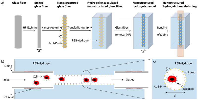
Nanostructured hydrogel channels were fabricated in a four-step process (Figure 1):
Figure 1.
a) Schematic of the fabrication procedure of nanostructured hydrogel channels (Step-by-step process). b) Side-view of the biofunctionalized channel setup. c) Cross-sectional view of the biofunctionalized channel. a)–c) are not to scale.
Etching of glass fibers to control fiber (channel) diameter and curvature
Nanostructuring of the fibers
Hydrogel polymerization around the fiber and removal of the glass fiber
Hydrogel swelling, detachment of the hydrogel from the mold, attachment of tubing and integration into the microfluidic setup
Fiber etching
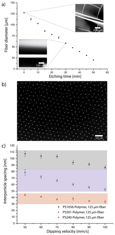
Glass fibers of high quality and purity for optical applications can be purchased. Unfortunately, the combined diameters of the core and the glass cladding are usually 125 μm or larger. It is desirable to tune the diameter of the hydrogel channels in the range below 100 μm because curvature effects will be most important when channel diameter and cell size are within the same order of magnitude. In nature, small vessels have diameters smaller than 100 μm and capillaries can have diameters of less than 10 μm. Towards this end we used an etching process based on hydrofluoric acid (40 %) to reduce the fiber diameter. In Figure 2a the etching kinetics of 125 μm glass fibers are shown. The diameter decreased linearly with time. By adjusting the etching time, the fiber diameter can be controlled with great accuracy. The scanning electron microscopy (SEM) images (Figure 2a) revealed a smooth fiber surface without visible defects. This is a prerequisite for homogenous nanostructuring in the second step.
Figure 2.
Fabrication of the nanostructured glass fibers: (a) Hydrofluoric acid etching kinetics performed to obtain fibers with diameters <125 μm. Fiber diameters (± SD) decreased linearly with etching time. Inset: SEM images of the etched fibers. (b) SEM-image of an Au-NP array with 89 ± 11 nm spacing (d=125 μm). (c) By using different block copolymers and different dipping speeds the Au-NP spacing can be varied between 30–110 nm (± SD).
Nanostructuring of glass fibers
Block copolymer micelle lithography (BCML) is a commonly used method in nanotechnology. It can be used to fabricate quasi-hexagonal patterns of Au-NPs with nanoparticle spacings of 20–250 nm16. BCML is based on the dip coating of substrates in a solution of metal-loaded blockcopolymer micelles. Dip-coating leads to a film of micelles and solvent. After solvent evaporation block copolymer patterns are released. The film height is proportional to the deposited fluid volume. The volume itself is proportional to the absolute number of micelles. Therefore, the number of micelles/nanoparticles per area depends on the film height. On curved substrates, like glass fibers the film height h can be expressed as h ≤ rv2/3 with r being the fiber radius and v the dipping velocity17. Although this equation is valid only for Newtonian-fluids and can therefore not be directly applied in our case, it explains qualitatively why higher dipping velocities are necessary to achieve the same film height on fibers of smaller diameter.”
In our experiments an insufficient height of the deposited film led to fracturing of the toluene/micelles film and the formation of complex micelle microstructures (not shown). By adjusting the dipping velocity, the optimal range between sub-monolayer and multilayer coverage with micelles could be achieved. Three orders of magnitude higher dipping velocities than on planar surfaces were necessary to achieve similar nanostructures. Thus we used a fast linear motor based on a magnetic actuator (Faulhaber LM 1247) for dip coating. In Figure 2b, a typical SEM image of Au-NP arrays on a glass fiber (d = 125 μm) is shown. We changed the polymer length and the dipping velocity and were able to fabricate Au-NP arrays with nanoparticle spacings ranging from 30–110 nm, which overspans one order of magnitude in density (Figure 2c).
The dipping velocity had to be increased with decreasing fiber diameter because otherwise the film height was insufficient for homogenous coverage with micelles. To fabricate nanoparticle patterns (90 ± 5 nm) on 125 μm fibers, dipping velocities of 80 mm/s in comparison to 500 mm/s on 25 μm fibers were necessary (supplementary figure S1). In summary, by choosing a suitable polymer and dipping velocity, the spacing of Au-NP arrays can be adjusted (Figure 2c) for fibers of tunable diameters (S1).
Transferlithography and microfluidic setup
The Au-NP arrays on glass surfaces were transferred to PEG hydrogels by anchoring them inside the PEG-(diacrylate) during polymerization18,19. Especially for small fibers it is necessary to have a macroscopic handle that allows positioning of the fiber. Therefore, both ends of each nanostructured fiber were attached inside tubes (d= 0.254 mm), which could be affixed to the cuboid hydrogel mold. We functionalized the Au-NPs on the glass fibers with N,N′-bisacryloylcystamine, which can copolymerize with PEG-diacrylate via its acrylate-group. Then we added a mixture of PEG-diacrylate, water and initiator (M=700 g/mol). After UV-mediated polymerization the hydrogel was left to swell in water, leading to detachment from the mold. The glass fiber was removed by etching with 20% hydrofluoric acid over night. After extensive rinsing with water, the hydrogel channel was ready to use. In a final step the primary tubing was replaced by new tubing suitable for attachment to a syringe pump (inlet) and a waste deposit (outlet). To prevent diffusion of the UV glue into the hydrogel channel, we took great care to use small amounts of glue and cured the glue quickly following application.
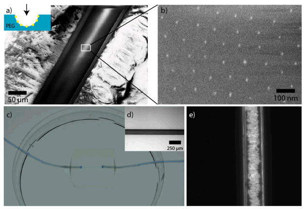
Figure 3 shows the final fabrication steps and the resulting functional channel. In Figure 3a, a Cryo-SEM image of a longitudinally dissected hydrogel channel is shown in small magnification. Figure 3b depicts the transferred Au-NPs on the PEG-channel’s inner surface.
Figure 3.
Transfer of the nanoparticles onto the hydrogel channel’s surface and microfluidic setup. (a) Cryo-SEM-image of a cut hydrogel channel (the viewer’s perspective is shown in the inset). The transfer of the Au-NP patterns is shown in the magnified Cryo-SEM-image in (b). There were no changes in the nanparticle pattern compared to the original glass fiber. (c) The channels were incorporated into a 20 × 20 × 4 mm hydrogel and they were sealed to tubes serving as inlets and outlets. For visualization the channel was filled with blue ink. The whole hydrogel channel system was bonded to a petri dish filled with water to prevent drying out. (d) Bright-field microscopy image of a hydrogel channel (125 μm) filled with ink. (e) Phase contrast image of a hydrogel channel (125 μm ) with 10 μm-sized polystyrene beads flowing through the channel.
Using UV glue, the microchannel-containing hydrogels were attached horizontally to the bottom of a petri dish, which was then flooded with water or cell culture medium to avoid drying of the hydrogel. The channel did not show any leaks after injecting ink, when observed with bright field light microscopy (Figure 3c, d). We infused standard polystyrene-microparticles (10 μm) into the channel using a syringe pump attached to the inlet tubing to visualize the behavior of cell-sized objects flowing through the nanostructured hydrogel channel (Figure 3e).
In summary, Cryo-SEM gave clear evidence that the Au-NP arrays were transferred entirely from the glass fiber to the inner surface of the hydrogel channel. The channel diameter was defined by the glass fiber and light microscopy showed the channel surfaces to be smooth. These properties prove the suitability of this system for use in microfluidic setups designed for the injection of cell-sized objects at defined flow rates.
P-selectin mediated rolling of cells
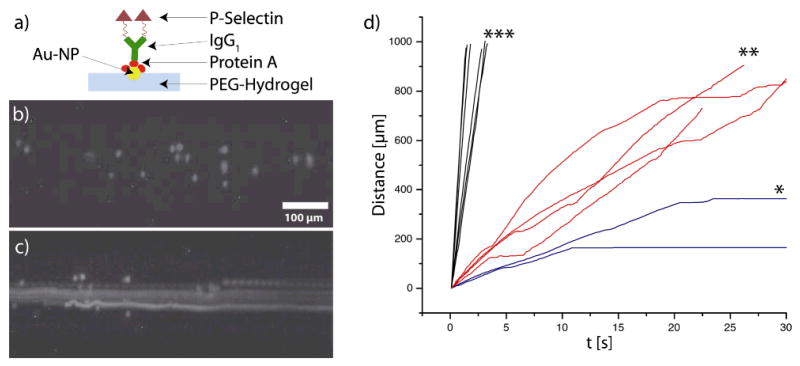
As a proof of principle we investigated the interaction of cells with the biofunctionalized hydrogel surface. A very important physiological process on vessel surfaces is tethering, rolling, attachment and adhesion of immune cells in the inflammatory cascade20. Therefore, we chose a P-selectin (CD62P)-IgG fusion protein for immobilization onto the gold nanoparticles in the channels. The single-chain glycoprotein P-selectin is rapidly upregulated upon inflammatory stimuli on activated endothelial cells and mediates the initial contact between vessel surfaces and leukocytes21. As a cellular model system we used KG1a cells, a human myeloid cell line which displays typical features both of neutrophils and hematopoietic progenitor cells22. Notably, this cell line expresses PSGL-1, the major counter-receptor for P-selectin23. P-selectin was immobilized to the Au-NPs on the inner channel surface by using Protein A (Figure 4a). Protein A binds to the Au-NPs and can bridge them to the Fc-part of the recombinant P-selectin24. Phase contrast microscopy of cells inside the hydrogel channels is hampered by the channel curvature, which distorts the optical path. To improve imaging we fluorescently labeled the cells with carboxyfluorescein succinimidyl ester (CFSE) before the experiment.
Figure 4.
Cell experiments in nanostructured hydrogel channels: a) Scheme presenting the biofunctionalization of the Au-NPs. b) Static fluorescence image of KG1a cells inside a nanostructured channel (125 μm). c) Overlay (maximum intensity) of 150 images showing the movement of different cells (sticking, freely floating or interacting) in a channel (125 μm) with 34 nm spacing. d) Representative trajectories of KG1a cells in channels (125 μm) equipped with functionalized gold nanoparticles of * 34 nm spacing, ** 108 nm spacing or *** no Au-NPs. Wall shear stress = 1 dyn/cm2.
We injected KG1a cells (1×10⁶/ml) into the channels via the inlet tubing. We chose a wall shear stress of 1 dyn/cm2, conditions under which leukocyte rolling and attachment has been reported for planar in vitro flow experiments25. A fluorescence image of KG1a cells inside the channel is shown in Figure 4b. The overlay of 150 images inside a channel (125 μm) with 34 nm spacing (Figure 4c) shows different cells, some freely flowing, some interacting and others adhering to the channel surface. Individual cell trajectories depended on the Au-NP (and respective P-selectin) spacing. Figure 4d shows representative trajectories of cells in different nanostructured channels (125 μm diameter). Cells attached firmly to the channel wall with the densest P-selectin spacing (34 nm) (* in Figure 4d). For smaller P-selectin densities (108 nm spacing) stop-and-go kinetics (** in Figure 4d) were observed. Such kinetics are in agreement with results from planar in vitro flow assays on P-selectin coated surfaces25. Cells in channels without Au-NPs (P-selectin) had higher velocities and did not show stop-and-go kinetics (*** in Figure 4d). These experiments show the importance of ligand density for cellular interactions under flow. In the future, this novel and highly tunable system may be used to generate state diagrams of specific cellular interactions with the parameters ligand, ligand density and channel wall curvature26.
Conclusions
We developed a new technique to fabricate circular hydrogel channels with biofunctionalized nanostructures. This approach provides an innovative tool to tailor channel wall curvature, surface biofunctionalization and biomolecule density of biocompatible hydrogel channels. It can be used for cell attachment and adhesion studies under flow or without flow. In combination with an inert PEG-hydrogel background it provides new features for cell experiments under flow. This method can serve as a valuable tool to investigate specific cell/surface interactions and create phase diagrams of cellular interactions.
Supplementary Material
Acknowledgments
We thank N. Perschmann, E. Kruss and U. Schwarz for fruitful discussions and N. Grunze for reading of the manuscript. S.K. was supported by the German National Academic Foundation, Fonds der Chemischen Industrie (FCI) and HBIGS (Heidelberg University). Funding by the FP7 programme (NanoII, NanoCARD) and the National Institutes of Health (USA, PN2 EY016586) is highly acknowledged.
Footnotes
Electronic Supplementary Information (ESI) available: [details of any supplementary information available should be included here]. See DOI: 10.1039/b000000x/
Notes and references
- 1.Young EWK, Beebe DJ. Chem Soc Rev. 2010;39:1036–1048. doi: 10.1039/b909900j. [DOI] [PMC free article] [PubMed] [Google Scholar]
- 2.Qin D, Xia Y, Whitesides GM. Nature Protocols. 2010;5:491–502. doi: 10.1038/nprot.2009.234. [DOI] [PubMed] [Google Scholar]
- 3.Schwarz US, Bischofs IB. Med Eng Phys. 2005;27:763–772. doi: 10.1016/j.medengphy.2005.04.007. [DOI] [PubMed] [Google Scholar]
- 4.Dunn GA, Heath JP. Exp Cell Res. 1976;101:1–14. doi: 10.1016/0014-4827(76)90405-5. [DOI] [PubMed] [Google Scholar]
- 5.Sanz-Herrera JA, Moreo P, Garcia-Aznar JM, Doblare M. Biomaterials. 2009;30:6674–6686. doi: 10.1016/j.biomaterials.2009.08.053. [DOI] [PubMed] [Google Scholar]
- 6.McMahon HT, Gallop JL. Nature. 2005;438:590–596. doi: 10.1038/nature04396. [DOI] [PubMed] [Google Scholar]
- 7.Yan WW, Liu Y, Fu BM. Biomech Model Mechanobiol. 2010;9:629–640. doi: 10.1007/s10237-010-0202-1. [DOI] [PubMed] [Google Scholar]
- 8.Abdelgawad M, Wu C, Chien WY, Geddie WR, Jewett MAS, Sun Y. Lab Chip. 2011;11:545–551. doi: 10.1039/c0lc00093k. [DOI] [PubMed] [Google Scholar]
- 9.Fiddes LK, Raz N, Srigunapalan S, Tumarkan E, Simmons CA, Wheeler AR, Kumacheva E. Biomaterials. 2010;31:3459–3464. doi: 10.1016/j.biomaterials.2010.01.082. [DOI] [PubMed] [Google Scholar]
- 10.Zhou J, Ellis AV, Voelcker NH. Electrophoresis. 2010;31:2–16. doi: 10.1002/elps.200900475. [DOI] [PubMed] [Google Scholar]
- 11.Arnold M, Cavalcanti-Adam EA, Glass R, Blümmel J, Eck W, Kantlehner M, Kessler H, Spatz JP. ChemPhysChem. 2004;5:383–388. doi: 10.1002/cphc.200301014. [DOI] [PubMed] [Google Scholar]
- 12.Ley K, Laudanna C, Cybulsky MI, Nourshargh S. Nat Rev Immunol. 2007;7:678–689. doi: 10.1038/nri2156. [DOI] [PubMed] [Google Scholar]
- 13.Regehr KJ, Domenech M, Koepsel JT, Carver KC, Ellison-Zelski SJ, Murphy WL, Schuler LA, Alarid ET, Beebe DJ. Lab Chip. 2009;9:2132–2139. doi: 10.1039/b903043c. [DOI] [PMC free article] [PubMed] [Google Scholar]
- 14.Cruise GM, Scharp DS, Hubbell JA. Biomaterials. 1998;19:1287–1294. doi: 10.1016/s0142-9612(98)00025-8. [DOI] [PubMed] [Google Scholar]
- 15.Cuchiara MP, Allen ACB, Chen TM, Miller JS, West JL. Biomaterials. 2010;31:5491–5497. doi: 10.1016/j.biomaterials.2010.03.031. [DOI] [PubMed] [Google Scholar]
- 16.Spatz J, Mossmer S, Hartmann C, Möller M. Langmuir. 2000;16:407–415. [Google Scholar]
- 17.Quéré D. Ann Rev Fluid Mech. 1999;31:347–384. [Google Scholar]
- 18.Graeter SV, Huang J, Perschmann N, López-Garcia M, Kessler H, Ding J, Spatz JP. Nano Lett. 2007;7:1413–1418. doi: 10.1021/nl070098g. [DOI] [PubMed] [Google Scholar]
- 19.Kruss S, Wolfram T, Martin R, Neubauer S, Kessler H, Spatz JP. Adv Mater. 2010;22:5499–5506. doi: 10.1002/adma.201003055. [DOI] [PubMed] [Google Scholar]
- 20.Mcever RP, Zhu C. Annu Rev Cell Dev Biol. 2010;26:363–396. doi: 10.1146/annurev.cellbio.042308.113238. [DOI] [PMC free article] [PubMed] [Google Scholar]
- 21.Schön MP, Zollner TM, Boehncke WH. J Invest Dermatol. 2003;121:951–962. doi: 10.1046/j.1523-1747.2003.12563.x. [DOI] [PubMed] [Google Scholar]
- 22.Koeffler HP, Billing R, Lusis AJ, Sparkes R, Golde DW. Blood. 1980;56:265–273. [PubMed] [Google Scholar]
- 23.Zannettino AC, Berndt MC, Butcher C, Butcher EC, Vadas MA, Simmons PJ. Blood. 1995;85:3466–3477. [PubMed] [Google Scholar]
- 24.Ghitescu L, Bendayan M. J Histochem Cytochem. 1990;38:1523–1530. doi: 10.1177/38.11.2212613. [DOI] [PubMed] [Google Scholar]
- 25.Alon R, Hammer DA, Springer TA. Nature. 1995;374:539–542. doi: 10.1038/374539a0. [DOI] [PubMed] [Google Scholar]
- 26.Beste MT, Hammer DA. PNAS. 2008;105:20716–20721. doi: 10.1073/pnas.0808213105. [DOI] [PMC free article] [PubMed] [Google Scholar]
Associated Data
This section collects any data citations, data availability statements, or supplementary materials included in this article.


