Abstract
Tip enhanced Raman scattering (TERS) microscopy is used to image antibody conjugated nanoparticles on intact cellular membranes. The combination of plasmonic coupling and the resultant electric field obtained from intermediate focusing of a radially polarized source gives rise to Raman images with spatial resolution below 50 nm. Finite element method calculations are used to explain the origins of the observed image resolution and spectroscopic signals. The observed Raman scattering provides information about the biomolecules present near the nanoparticle probes. The results show that aggregates of nanoparticles produce spectroscopic results similar to those reported from other surface enhanced Raman spectroscopies [e.g. – shell isolated nanoparticle enhanced Raman spectroscopy (SHINERS) and aggregated nanoparticles]; however, TERS enables the detection of isolated nanoparticles on cell membranes where the observed spectra provide information about the interaction of the specific biomolecule conjugated to the nanoparticle probe. These measurements present a new technique for exploring biomolecular interactions on the surface of cells and tissue.
Keywords: TERS, SERS, biomembranes, antibody, Raman, nanoparticles, radial polarization
Introduction
The ability to investigate complex, heterogeneous systems at the nanoscale remains an experimental challenge. Typically compromises are required to obtain specific information, such as functionalization with fluorescent probes or examination in ultrahigh vacuum. Raman scattering has long been recognized as a label-free method of investigating systems in wide ranging environments; however, the low intrinsic signal associated with the effect is an imposing limitation. Increased understanding of Raman signal enhancements associated with metal nanostructures, the origins of surface enhanced Raman scattering (SERS)1, 2, have transformed Raman into a viable method of ultra-sensitive detection.3, 4 Molecules that experience the enhanced electric fields can generate Raman signals enhanced as much as 1011. 2, 5, 6
Tip enhanced Raman scattering (TERS) microscopy has also emerged as a useful technique for obtaining Raman images on nanometer dimensions.7, 8 In TERS, the nanostructure is located at the apex of a scanning probe microscope tip and generates enhanced Raman scattering from those molecules within close proximity of a few nanometers of the tip. Increased understanding of the plasmonic interactions associated with TERS has shown that the greatest Raman enhancements originate from ultra-sharp tips or from gap-modes, junctions, created by bringing the metallic tip within 1–2 nm of a metal surface with the molecule of interest in the middle.9–11 TERS has found broad application from silicon12 and other materials to biological systems13, 14 and single molecule imaging8, 15.
Cellular membranes represent a challenge for TERS microscopy. The chemical interactions that regulate lipid-lipid, lipid-protein, and protein-protein interactions have proven to be quite sensitive to external perturbation.16 The label-free nature of TERS appears a promising method of investigating these systems;14, 17 however, the heterogeneity and dynamic nature of cell membranes continues to present challenges. One of these challenges is recognizing the relevant region of the membrane to investigate. Because cells typically range 10’s of micrometers in size, it is challenging to identify the region measure with nanometer resolution.
Targeted TERS is our approach to capitalize on increased sensitivity of Raman detection associated with nanostructure clusters, while providing nanoscale spatial information from a specific membrane receptor. In a previous communication18 we employed TERS imaging methodology to enhance the intrinsic Raman scattering of a biotin-functionalized nanoparticle bound to a surface immobilized streptavidin protein and observed spatial resolution that correlates with the size of the biotinylated nanoparticles. In this research, we took this process a step further and measured the Raman scattering from anti-IgG labeled Au nanoparticles bound to the plasma membrane of colon cancer cells. One aspect of our data that cannot be immediately explained without a better understanding of the plasmonic coupling between the TERS tip and the nanoparticle is the apparent super-resolution of the detected Raman signal. In particular, the spatial resolution appears asymmetrically in x and y directions. Multiple scans over the locus of the nanoparticles indicate reproducibility and argue against physical displacement of the particle. The observed signals are on spatial dimensions below that expected for near-field detection from a linearly polarized source, where the spatial resolution is on the order of 200 nm.19 From these observations, we hypothesize that the plasmon coupling must have a more complex profile as the tip passes over the nanoparticle, with non-negligible interactions from the radial polarization occurring between the induced plasmons in both the tip and the nanoparticle probe. In order to investigate this possibility, we have modeled the plasmonic properties of the monomer and various relevant heterodimer configurations using finite element methods. The combination of experimental and computational results illustrates an effective way to target specific receptors on cellular membranes for characterization by near-field Raman spectroscopy.
Experimental
TERS microscopy was performed using 632.8 nm laser excitation in our microscope, reported previously,18 consisting of a Nanonics MV4000 atomic force microscope (AFM) and a home built Raman spectrometer. The TERS tip in these experiments is a Au-nanoparticle on a glass cantilever, CMP-TERS tips (Nanonics Supertips, LTD). To facilitate detection of nanoparticles, the TERS microscope was modified to enable dark-field microscopy. Hyperspectral dark-field microscopy was performed using a CytoViva hyperspectral dark-field system. Complete details are available in the supporting information.
Antibody conjugation was performed by standard EDC coupling using a conjugation kit (Nanopartz, Inc), and characterized as described in the supporting information.
Finite element method (FEM) calculations were performed using COMSOL with more complete details provided in the supporting information.
There research reported has no safety concerns beyond standard, OSHA approved, safe chemical and laser safety procedures.
Results and Discussion
Conjugated Nanoparticle Characterization
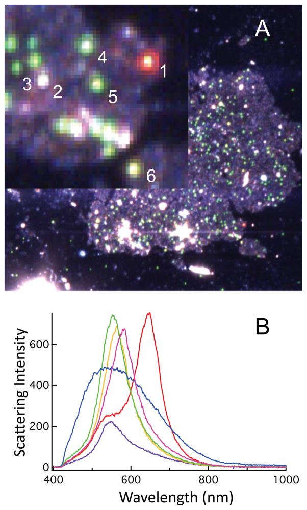
Antibody conjugated nanoparticles were incubated with cells and further characterized by hyperspectral dark-field microscopy. In the dark-field images (Figure 1), we again see particles indicative of isolated and aggregated particles. Some particles show increased brightness, suggestive of to two particles within the detection volume but not strongly coupled. The scattering maxima measured from these particles varies form 550 – 585 nm. For particles examined in the absence of cells (Figure S-1), a relatively uniform scattering signal is observed. Other red-colored particles evinced the expected split spectral lineshape characteristic of strongly coupled nanoparticles.20
Figure 1.
The dark field image of our 50 nm conjugated nanoparticles affixed to cells is shown in A. The inset is a blow-up of the area marked by the red box. The spectrum obtained from the circled particles are plotted in B. Individual particles exhibit small differences in their scattering maxima suggesting multiple particles within the diffraction limited focus with weak coupling interactions, while aggregated particles (e.g.- particle 1) are detected by their red color and characteristic spectral profile (red). Particles that are not Au (e.g.- particle 2) are evident by the different scattering profile they evince (blue). The purple, green, yellow, and magenta spectra correspond to particles 3, 4, 5, and 6, respectively.
In our TERS experiments, we were able to detect Raman scattering from both isolated and clustered anti-IgG labeled nanoparticles that were bound to the plasma membrane of cells in the TERS images. In control experiments we were unable to detect unconjugated carboxy-treminated nanoparticles by TERS despite evidence of plasmonic particles in the dark-field image, suggesting that unfunctionalized nanoparicles are endocytosed by the cells. Particles within the cells are not detectable by TERS, but are still observable by dark field microscopy. The fate of these particles within the cells is not within the scope of these experiments. Subtle shifts in the scattering spectra of particles within cells may also suggest different dielectric environments representative of where the nanoparticles are located (Figure 1).
TERS Microscopy
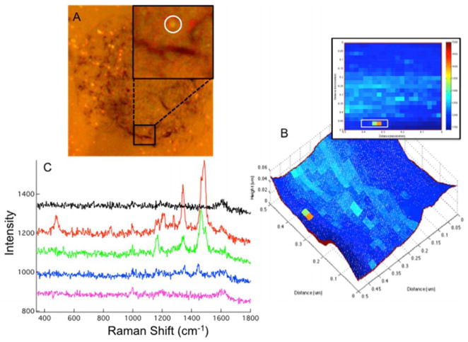
TERS images were acquired from regions of the cell membrane where nanoparticle scattering was indicative of isolated particles. During the TERS scan, strong electric fields located at the surface of the Au tip excited vibrational modes from molecules on the cell membrane, producing a weak Raman scattering signal. This weak scattering is consistent with previous signals observed in TERS microscopy that often require longer acquisitions times to clearly discern. We noticed, however, a strong enhancement of the anti-IgG signal in the immediate vicinity of the nanoparticle as shown in Figure 2. The observed Raman signal was significantly greater than that observed from the cell membrane alone, and was verified over multiple scans.
Figure 2.
(A) The bright field image of 50 nm Au nanoparticles on a cell is shown. The Inset provides a zoom in of the region imaged by TERS. (B) The topography from the AFM measurement is overlaid with baseline subtracted Raman intensity at 1485 cm−1. (B) Raman heat map of the anti-IgG 1485 cm−1 baseline subtracted peak intensity is shown in 2-D for area scanned. (C) The Raman spectra of anti-IgG obtained from a single Au nanoparticle are shown. The plotted spectra correspond to the pixels in the white box on the 2-D projection (inset of B).
The bands observed in figure 2C at 1465, 1340, and 1170 cm−1 are in strong agreement with the peaks observed in the SERS spectrum of isolated conjugated nanoparticles (Figure S-2). These peaks have been previously assigned to ring modes of aromatic amino acids, most likely tryptophan, present in anti-IgG antibodies.21 At the position with the greatest Raman scattering intensity in the Raman map (Fig. 2B), additional peaks are observed at 1485, 1210, and 485 cm−1. The peak are 1210 and 1485 cm−1 can be attributed to a tyrosine residue. 21 The peak at 485 cm−1 was previously shown to be characteristic of a disulfide bond conformational change associated with IgG antibody – antigen interaction.22 The detection of the 485 cm−1 band, in particular, indicates that the Raman scattering is sensitive to interactions between the conjugated antibody on the nanoparticle probe and antigens on the cellular membrane.
The strong enhancement of the anti-IgG Raman bands correlates with the observation of an isolated nanoparticle in the optical microscopy. There is some variation in the observed intensities as the tip scans across the nanoparticle. The change in intensity may arise from the magnitude of the field attendant to the dimer at different distances; or it may suggest a change in the direction of the induced polarization as the tip and nanoparticle interact, probing different resonances.
The observed resonances are all attributable to the antibody. The observed scattering suggests an isolated particle. Nanoparticles are exposed to cells while the cells are still viable. The bound nanoparticles are not readily detectable in the measured topography of the membrane (Fig. 2C), suggesting that the cell membrane restructures around the nanoparticle. Complete endocytosis would inhibit plasmonic coupling and TERS detection. The dimensions of the observed Raman enhancement, however, are consistent with our previous results18 that indicate a single nanoparticle is being detected. The half width of the observed signal is 40 nm in x and 20 nm in the y direction.
The dramatic increase in signal observed when the tip passes over the Au nanoparticle can be attributed to two effects. First, it has been demonstrated that when two noble metal nanoparticles are brought in close proximity to one another (e.g. the distance of a few nanometers), their localized surface plasmons can couple through near-field interactions, thereby creating greatly enhanced electric fields and, subsequently, large SERS enhancements at the metal surface and especially at the interparticle gap.18, 23–25 In this experiment, when the TERS tip comes in close proximity to the anti-IgG functionalized nanoparticle, a small gap is formed between the two metal structures. Our AFM uses tuning fork feedback, thus the tip is oscillating with an amplitude of a few nanometers near the nanoparticle and spends time at a distance optimum (1–2 nm)3, 10 for the field enhancement. From the observed Raman bands, we are primarily detecting the antibody; however, the spectrum shows evidence of interactions with antigens on the cell membrane.
The second effect is attributed to the shift in the plasmon frequency that arises from the coupling of the TERS tip and the bound nanoparticle during the temporary heterodimer formation. We measured a scattering maximum for our 50 nm Au nanoparticle colloid at 545 nm (Figure S-1). When the tip is brought close, the individual localized surface plasmon resonances (LSPR) of the tip and the nanoparticle interact, causing the plasmon resonance frequency to shift to longer wavelengths.23, 25–27 Coupling between nanoparticles shifts the plasmon resonance frequency closer to the 633 nm excitation frequency, thereby increasing the enhancement of the Raman signal from the molecules in the immediate vicinity of the metal surface. The shift in plasmon frequency is straightforwardly identified in scattering spectra of particles (eg - Fig 1). The enhancement increases the scattering efficiency of the anti-IgG molecules, giving rise to the spectra shown in Figure 2C.
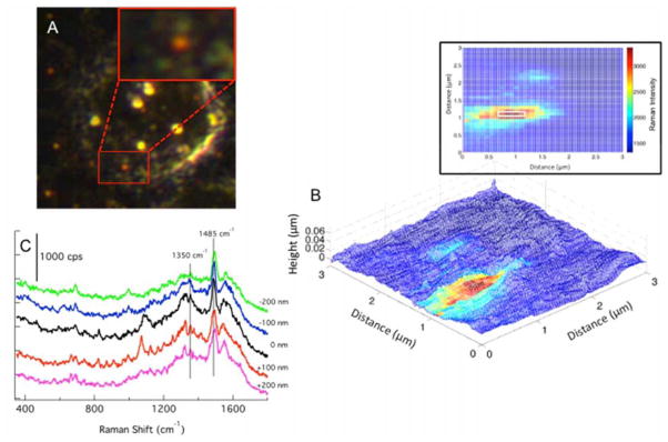
In addition to spectral scans taken from individual nanoparticles attached to cells, we also investigated clusters of nanoparticles. Shown in Figure 3, clusters of nanoparticles are readily identified from the red scattering observed in the dark-field image. The spectra observed from clusters, shown in Figure 3 contains a plethora of peaks in comparison to the spectrum observed from an isolated particle. This abundance of peaks does not lead to straightforward identification. Interestingly, with the exception of the band at 1485 cm−1 and in the region of 1350 cm−1, the anti-IgG peaks observed from single particles are not prominent in this spectrum. The spectral diversity observed from this cluster is likely representative of the heterogeneous composition of cellular membranes. Identification of specific biomolecular components can be complicated under these conditions. The observation of multiple peaks is consistent with other enhanced Raman methodologies, such as shell-isolated nanoparticle-enhanced Raman spectroscopy (SHINERS).28
Figure 3.
(A) The dark field image of a single cell is shown. The region scanned by TERS is shown in the red box and enlarged in the inset. (B) The AFM topography is overlaid with the Raman map from the baseline subtracted intensity of the peak at 1575 cm−1. The Raman map in 2-D is shown (inset) to help visualize the dimensions of the nanoparticle cluster detected in the far field image and by TERS. (C) The spectrum from 5 pixels (white box, inset of B) across the center of the high intensity area are plotted. The spectrum from the cluster shows signals at 1350 and 1485 cm−1 consistent with the conjugated nanoparticles (Fig. S2) and that of the spectrum of a single Au NP shown in Fig. 2C; however, the spectra also contain many signals not directly attributed to the IgG antibody.
These results emphasize the unique ability of TERS analysis to detect isolated nanoparticles, rather than large clusters. The differences in the Raman spectrum obtained from individual nanoparticles as compared to clusters of nanoparticles likely originate from two effects. First, when nanoparticles aggregate, a multitude of hot spots are created in the gaps between adjacent particles in addition to the gap that is created by the scanning tip due to additional dipole-dipole coupling. Consequently, when a cluster is scanned, Raman modes from the molecule in different orientations and locations along the particle can be accessed. Second, clusters of nanoparticles can and will enhance molecules other than the molecule of interest, giving rise to spurious peaks that obfuscate the spectrum of the molecule to be measured. For clusters, this is difficult to control. The results from an isolated nanoparticle show a reduced data set that is controlled by the plasmonic interactions between the tip and the nanoparticle probe. The spectra in Figure 2C nicely exhibit how increased coupling provides details about a limited number of residues on the probe. All of these factors combined emphasize the importance of imaging single nanoparticles.
FEM calculations
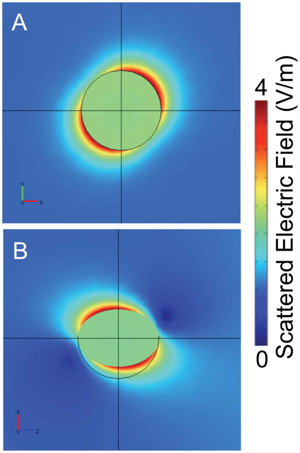
To understand the influence of radial polarization focused with an intermediate NA objective and the interactions with the resulting electric field at the focus, the nanoparticle tip and conjugated-nanoparticle probe, we performed FEM calculations. First we modeled the scattered electric field resulting from a single nanoparticle under multiple polarizations. From this calculation shown in Figure 4A, the electric field is oriented along the line x=y in the x–y plane. In Figure 4B, projection onto the x–z plane shows that the electric field is further tilted in z, suggesting an octupole-like nature to the electric field around the spherical particle. Both of these attributes are presumed to arise from the interplay between the three polarization components and their respective interactions with the plasmon resonances of the monomer. This calculation is consistent with the model reported by Youngworth and Brown, where at high NA, the z-component dominates and orients the field predominantly along the z-axis.29 The apparent asymmetry, suggests that these particles will behave atypically with respect to interactions associated with coupled electric fields. In particular, there should be a unique position where the maximum anti-IgG Raman signal is observed, contrary to previous reports with linear polarized light.19
Figure 4.
Scattered electric field normal for a 50 nm Au nanoparticle illuminated with a radially polarized source is shown as determined by our COMSOL model. (A) The projection of the electric field strength in the x–y plane reveals the orientation of the maximum enhancement along the 45° diagonal. (B) The map of the electric field in the p1=(1, 1, 1), p2=(1, 1, 0), p3=(0, 0, 0) plane is projected into the x–z plane. The calculation show a dominant scattered field along the line x=y but tilted above and below the plane.
The radial polarization employed provides a spatially non-uniform polarization that results in a polarization component along the direction of propagation within the focus, a longitudinal mode.11, 30 Youngworth and Brown reported that the strength of this longitudinal component is directly related to the numerical aperture (NA) of the microscope objective used, with very high NA objectives eventually producing longitudinal fields that exceed the strength of the corresponding transverse fields.29 Their calculations indicated that at moderate NA, the longitudinal component of the field was diminished, but not zero. For a NA=0.7 (the value for the objective used in the experiments described herein) the expected ratio of z-polarization to in plane polarization is approximately 0.8.
In order to model the dependence of the SERS enhancement of the tip-nanoparticle configuration, we further performed FEM analysis of a Au nanoparticle pair. It is well known that the enhancement arising from dimer structures usually exceeds the monomer enhancement by several orders of magnitude.3, 6 The enhancement from coupled particles is exquisitely sensitive to the morphology of the dimer, interparticle spacing, and orientation with respect to the polarization of the excitation source. 3, 25, 26, 31
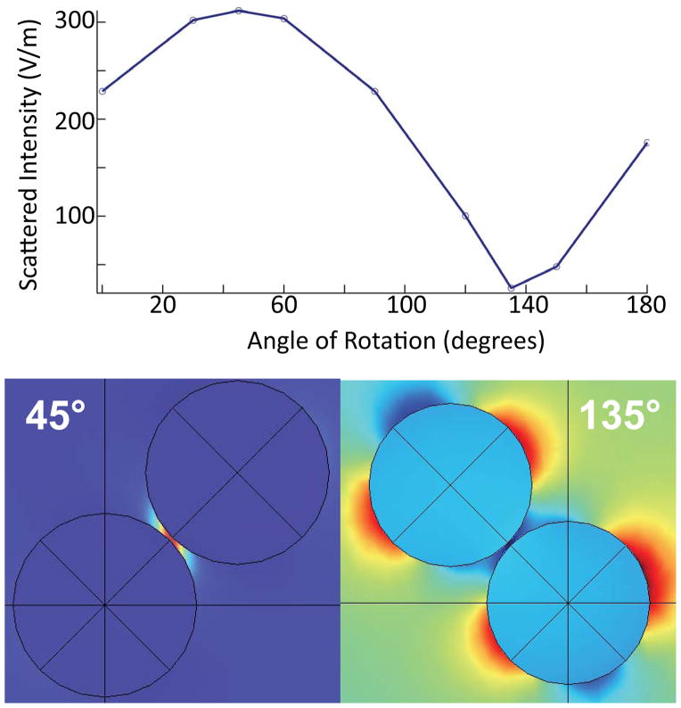
To model the orientation dependence we calculated the scattered field from a pair of nanoparticles as shown in Figure 5. One sphere (representing the anti-IgG labeled nanoparticle) was held fixed at the origin while the other sphere (representing the TERS tip) was rotated over a range of 0–180 degrees while maintaining a 2 nm gap between the two surfaces. The relationship between the nanoparticles was fixed to provide a uniform gap and only the angular dependence with respect to the electric field was varied. In Figure 5, we noticed a sinusoidal dependence of the scattered electric field strength, with a maximum appearing at the 45 degree mark where the dipoles of the tip and the fixed nanoparticle are aligned as well as a minimum at the 135 degree mark where the dipoles are parallel but not in-line.
Figure 5.
COMSOL simulations of the angular dependence of the maximum of the normal of the scattered electric field for two 50 nm Au nanoparticles with a 2 nm interparticle gap. The illustrations below show normalized scattered field (red is the greatest and dark blue is the lowest scattering) that correspond to 45° and 135°, the maximum and minimum scattering points.
The LSPR coupling between the tip and particle creates an electric dipole that serves as the effective polarization for exciting Raman scattering. It is well known that maximum Raman scattering is radiated perpendicular to the direction of the polarization and has a strength that is directly related to the magnitude of the induced dipole moment of the radiating structure. Because the signal in these experiments is collected in the backscattering configuration, the strongest signals are induced when the particles approach 45°, inducing a local polarization at 45°, increasing the amount of scattered light into the collection cone of the microscope objective, thereby allowing for more sensitive Raman measurements.
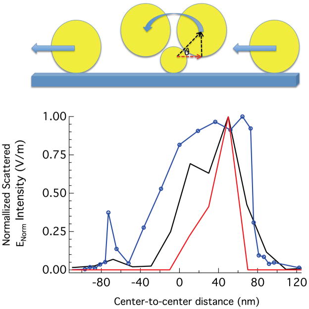
To simulate a TERS scan, we calculated the scattered field as a 100 nm particle (the tip) was moved across a stationary 50 nm particle as shown in Figure 6. Incorporating the nanoparticle size asymmetry provides a better representation of the experimental conditions. In Figure 6, the x–y plane is assumed to represent the surface of the substrate and the tip distance is varied over a range of 2 to 100 nm on both sides of the nanoparticle with respect to the x-axis. When the model tip reaches a distance of 2 nm from the surface of the second nanoparticle, it is rotated 180 degrees about the origin while keeping the interparticle gap constant. In the case of asymmetric nanoparticles the scattered field shows a sharp asymmetric drop off in contrast to the sinusoidal dependence observed for identical particles (Fig. 5) or reports using linear polarization.19
Figure 6.
COMSOL simulation results (blue, data points) of the scattered electric field intensity maxima where the center-to-center distance and angular position is varied for the tip-nanoparticle system. Because the center-to-center distance remains fixed when the angular positioned is varied, the position of the tip is described by the projection of the center-to-center distance on the x-axis. The simulation is overlaid with the intensity profile from a single nanoparticle on cell membrane (red) and from our previous results of a single nanoparticle on a glass surface (black).18 The illustration depicts the path the tip takes over the nanoparticle used in the model.
The asymmetry observed in the scan direction from the enhanced anti-IgG signal can be explained by changes in the coupling strength at the tip scans over the nanoparticle, with maximum enhancement occurring when the induced electric fields in the nanoparticles align, which is asymmetric as shown in figure 6. From the measured topography, the nanoparticles tend to sink into the cell membrane, which appears to affect the observed Raman scattering. We suspect that this recession inhibits the tip access along the sides of the target nanoparticle, resulting the abbreviated spectral profiles. In the scan direction, the observed signal half width is 40 nm. However, the results of these simulations show a high degree of correlation when compared to previous results from nanoparticles on solid surfaces. In Figure 6, we overlaid the simulation data with the intensity profiles we obtained by performing the same experiments on isolated biotinylated nanoparticles on a streptavadin-derivatized substrate,18 and from the isolated nanoparticle detected in Figure 2, demonstrating that the two intensity profiles are roughly congruent. Specifically, both the experimental and the theoretical data show asymmetric signal enhancements with improved spatial resolution in comparison to results utilizing linear polarized light.
The TERS imaging shows asymmetric resolution around the detected nanoparticles. Specifically, in our images the y-resolution is finer than the in x. The resolution in x is explained above, but to understand this asymmetry, we modeled the plasmonic coupling between the tip and the nanoparticle in the case that the tip is offset +/− 20 nm along the y-axis (Figure S-2), modeling the raster scan pattern in the TERS image. A small offset gives rise to a situation where the tip approaches the nanoparticle, but the dipole alignment differs substantially. The calculations show this change in dipole alignment drastically affects the coupling between the tip and the nanoparticle and contributes to different enhancements in x and y.
Conclusions
We have demonstrated the ability to spectroscopically image biomolecules attached to single nanoparticles on intact cellular membranes. The conjugated nanoparticles provide a mechanism to readily identify the membrane region of interest. The combination of plasmon coupling and the orientation of the induced polarization provided spatial resolution better than 50 nm, while providing chemically specific information, which, in these results, is relevant to the antibody-antigen interaction. The experimental and computational results explain the effect that multiple polarizations have on the electric fields experienced by individual nanoparticles and subsequently, on the observed imaging resolution. The electric field resulting from focusing radial polarization at an intermediate numerical aperture results in greatly improved spatial resolution compared to results from linear polarization. This combination of experiment and modeling indicates an exciting new route to exploring biomolecular interactions on cellular membranes.
Supplementary Material
Acknowledgments
The authors thank CytoViva, Inc. for assistance obtaining hyperspectral dark field images of the conjugated nanoparticles. The National Institutes of Health through award R00RR024367 and the Walther Cancer Foundation provided financial support for this research.
Footnotes
Supporting Information Available: Detailed experimental methods and Figures S-1, S-2, and S-3 are available free of charge via the Internet at http://pubs.acs.org.
References
- 1.Lee SJ, Guan ZQ, Xu HX, Moskovits M. Surface-enhanced Raman spectroscopy and nanogeometry: The plasmonic origin of SERS. J Phys Chem C. 2007;111:17985–17988. [Google Scholar]
- 2.Stiles PL, Dieringer JA, Shah NC, Van Duyne RR. Surface-Enhanced Raman Spectroscopy. Annu Rev Anal Chem. 2008;1:601–626. doi: 10.1146/annurev.anchem.1.031207.112814. [DOI] [PubMed] [Google Scholar]
- 3.Wustholz KL, Henry AI, McMahon JM, Freeman RG, Valley N, Piotti ME, Natan MJ, Schatz GC, Duyne RPV. Structure-Activity Relationships in Gold Nanoparticle Dimers and Trimers for Surface-Enhanced Raman Spectroscopy. J Am Chem Soc. 2010;132:10903–10910. doi: 10.1021/ja104174m. [DOI] [PubMed] [Google Scholar]
- 4.Stranahan SM, Willets KA. Super-resolution Optical Imaging of Single-Molecule SERS Hot Spots. Nano Lett. 2010;10:3777–3784. doi: 10.1021/nl102559d. [DOI] [PubMed] [Google Scholar]; Graham D, Stevenson R, Thompson DG, Barrett L, Dalton C, Faulds K. Combining functionalised nanoparticles and SERS for the detection of DNA relating to disease. Faraday Discuss. 2011;149:291–299. doi: 10.1039/c005397j. [DOI] [PubMed] [Google Scholar]; Larmour IA, Faulds K, Graham D. The past, present and future of enzyme measurements using surface enhanced Raman spectroscopy. Chemical Science. 2010:151–160. [Google Scholar]
- 5.Kudelski A. Raman spectroscopy of surfaces. Surf Sci. 2009;603:1328–1334. doi: 10.1016/j.susc.2008.11.039. [DOI] [Google Scholar]; Kneipp J, Kneipp H, Kneipp K. SERS-a singlemolecule and nanoscale tool for bioanalytics. Chemical Society Reviews. 2008;37:1052–1060. doi: 10.1039/b708459p. [DOI] [PubMed] [Google Scholar]
- 6.Moskovits M. Surface-enhanced Raman spectroscopy: a brief retrospective. Journal of Raman Spectroscopy. 2005;36:485–496. doi: 10.1002/jrs.1362. [DOI] [Google Scholar]
- 7.Pettinger B. In: Top Appl Phys. Kneipp K, Moskovits M, Kneipp H, editors. Vol. 103. Springer; Berlin: 2006. pp. 217–240. [Google Scholar]; Deckert-Gaudig T, Deckert V. Nanoscale structural analysis using tip-enhanced Raman spectroscopy. Curr Opin Chem Biol. 2011;15:719–724. doi: 10.1016/j.cbpa.2011.06.020. [DOI] [PubMed] [Google Scholar]; Yeo BS, Stadler J, Schmid T, Zenobi R, Zhang WH. Tip-enhanced Raman Spectroscopy - Its status, challenges and future directions. Chem Phys Lett. 2009;472:1–13. [Google Scholar]
- 8.Ichimura T, Fujii S, Verma P, Yano T, Inouye Y, Kawata S. Subnanometric Near-Field Raman Investigation in the Vicinity of a Metallic Nanostructure. Phys Rev Lett. 2009;102:186101–4. doi: 10.1103/PhysRevLett.102.186101. [DOI] [PubMed] [Google Scholar]
- 9.Deckert-Gaudig T, Bailo E, Deckert V. Tip-enhanced Raman scattering (TERS) of oxidised glutathione on an ultraflat gold nanoplate. Physical Chemistry Chemical Physics. 2009;11:7360–7362. doi: 10.1039/b904735b. [DOI] [PubMed] [Google Scholar]; Pettinger B, Domke KF, Zhang D, Picardi G, Schuster R. Tip-enhanced Raman scattering: Influence of the tip-surface geometry on optical resonance and enhancement. Surf Sci. 2009;603:1335–1341. doi: 10.1016/j.susc.2008.08.033. [DOI] [Google Scholar]
- 10.Pettinger B, Domke KF, Zhang D, Schuster R, Ertl G. Direct monitoring of plasmon resonances in a tip-surface gap of varying width. Phys Rev B. 2007:76. [Google Scholar]
- 11.Novotny L, Stranick SJ. Near-field optical microscopy and spectroscopy with pointed probes. Annual Review of Physical Chemistry. 2006;57:303–331. doi: 10.1146/annurev.physchem.56.092503.141236. [DOI] [PubMed] [Google Scholar]
- 12.Hayazawa N, Motohashi M, Saito Y, Ishitobi H, Ono A, Ichimura T, Verma P, Kawata S. Visualization of localized strain of a crystalline thin layer at the nanoscale by tip-enhanced Raman spectroscopy and microscopy. Journal of Raman Spectroscopy. 2007;38:684–696. [Google Scholar]
- 13.Wood BR, Bailo E, Khiavi MA, Tilley L, Deed S, Deckert-Gaudig T, McNaughton D, Deckert V. Tip-Enhanced Raman Scattering (TERS) from Hemozoin Crystals within a Sectioned Erythrocyte. Nano Lett. 2011;11:1868–1873. doi: 10.1021/nl103004n. [DOI] [PubMed] [Google Scholar]
- 14.Mariani MM, Maccoux LJ, Matthaus C, Diem M, Hengstler JG, Deckert V. Micro-Raman Detection of Nuclear Membrane Lipid Fluctuations in Senescent Epithelial Breast Cancer Cells. Anal Chem. 2010;82:4259–4263. doi: 10.1021/ac1006987. [DOI] [PubMed] [Google Scholar]
- 15.Steidtner J, Pettinger B. Tip-enhanced Raman spectroscopy and microscopy on single dye molecules with 15 nm resolution. Phys Rev Lett. 2008:100. doi: 10.1103/PhysRevLett.100.236101. [DOI] [PubMed] [Google Scholar]
- 16.Veatch SL, Leung SSW, Hancock REW, Thewalt JL. Fluorescent probes alter miscibility phase boundaries in ternary vesicles. J Phys Chem B. 2007;111:502–504. doi: 10.1021/jp067636i. [DOI] [PubMed] [Google Scholar]; Shaw JE, Epand RF, Epand RM, Li ZG, Bittman R, Yip CM. Correlated fluorescence-atomic force microscopy of membrane domains: Structure of fluorescence probes determines lipid localization. Biophys J. 2006;90:2170–2178. doi: 10.1529/biophysj.105.073510. [DOI] [PMC free article] [PubMed] [Google Scholar]; Wang TY, Silvius JR. Different sphingolipids show differential partitioning into sphingolipid/cholesterol-rich domains in lipid bilayers. Biophys J. 2000;79:1478–1489. doi: 10.1016/S0006-3495(00)76399-5. [DOI] [PMC free article] [PubMed] [Google Scholar]; Johnston LJ. Nanoscale Imaging of Domains in Supported Lipid Membranes. Langmuir. 2007;23:5886–5895. doi: 10.1021/la070108t. [DOI] [PubMed] [Google Scholar]; Chan YHM, Boxer SG. Model membrane systems and their applications. Current Opinion in Chemical Biology: Model systems/Biopolymers. 2007;11:581–587. doi: 10.1016/j.cbpa.2007.09.020. [DOI] [PMC free article] [PubMed] [Google Scholar]
- 17.Bohme R, Richter M, Cialla D, Rosch P, Deckert V, Popp J. Towards a specific characterisation of components on a cell surface - combined TERS-investigations of lipids and human cells. Journal of Raman Spectroscopy. 2009;40:1452–1457. doi: 10.1002/jrs.2433. [DOI] [Google Scholar]; Neugebauer U, Rosch P, Schmitt M, Popp J, Julien C, Rasmussen A, Budich C, Deckert V. On the way to nanometer-sized information of the bacterial surface by tip-enhanced Raman spectroscopy. ChemPhysChem. 2006;7:1428–1430. doi: 10.1002/cphc.200600173. [DOI] [PubMed] [Google Scholar]; Opilik L, Bauer T, Schmid T, Stadler J, Zenobi R. Nanoscale chemical imaging of segregated lipid domains using tip-enhanced Raman spectroscopy. Physical Chemistry Chemical Physics. 2011;13:9978–9981. doi: 10.1039/c0cp02832k. [DOI] [PubMed] [Google Scholar]
- 18.Carrier SL, Kownacki CM, Schultz ZD. Protein-ligand binding investigated by a single nanoparticle TERS approach. Chem Commun. 2011;47:2065–2067. doi: 10.1039/c0cc05059h. [DOI] [PMC free article] [PubMed] [Google Scholar]
- 19.Olk P, Renger J, Hartling T, Wenzel MT, Eng LM. Two particle enhanced nano Raman microscopy and spectroscopy. Nano Lett. 2007;7:1736–1740. doi: 10.1021/nl070727m. [DOI] [PubMed] [Google Scholar]
- 20.Halas NJ, Lal S, Chang WS, Link S, Nordlander P. Plasmons in Strongly Coupled Metallic Nanostructures. Chem Rev. 2011;111:3913–3961. doi: 10.1021/cr200061k. [DOI] [PubMed] [Google Scholar]
- 21.Grabbe ES, Buck RP. Evidence for a Conformational Change with Potential of Adsorbed Anti-IgG Alkaline-Phosphatase Conjugate at the Silver Electrode Interface Using SERS. Journal of Electroanalytical Chemistry. 1991;308:227–237. doi: 10.1016/0022-0728(91)85069-2. [DOI] [Google Scholar]
- 22.Fagnano C, Fini G. Antibody Antigen Interactions Studied by Means of Raman-Spectroscopy. Journal of Raman Spectroscopy. 1992;23:637–639. doi: 10.1002/jrs.1250231112. [DOI] [Google Scholar]
- 23.Gunnarsson L, Rindzevicius T, Prikulis J, Kasemo B, Kall M, Zou SL, Schatz GC. Confined plasmons in nanofabricated single silver particle pairs: Experimental observations of strong interparticle interactions. J Phys Chem B. 2005;109:1079–1087. doi: 10.1021/jp049084e. [DOI] [PubMed] [Google Scholar]; Encina ER, Coronado EA. Plasmon Coupling in Silver Nanosphere Pairs. J Phys Chem C. 2010;114:3918–3923. doi: 10.1021/jp912096v. [DOI] [Google Scholar]; Sheikholeslami S, Jun YW, Jain PK, Alivisatos AP. Coupling of Optical Resonances in a Compositionally Asymmetric Plasmonic Nanoparticle Dimer. Nano Lett. 2010;10:2655–2660. doi: 10.1021/nl101380f. [DOI] [PubMed] [Google Scholar]
- 24.Romero I, Aizpurua J, Bryant GW, de Abajo FJG. Plasmons in nearly touching metallic nanoparticles: singular response in the limit of touching dimers. Optics Express. 2006;14:9988–9999. doi: 10.1364/oe.14.009988. [DOI] [PubMed] [Google Scholar]; Kelly KL, Coronado E, Zhao LL, Schatz GC. The optical properties of metal nanoparticles: The influence of size, shape, and dielectric environment. J Phys Chem B. 2003;107:668–677. doi: 10.1021/jp026731y. [DOI] [Google Scholar]; Link S, El-Sayed MA. Spectral properties and relaxation dynamics of surface plasmon electronic oscillations in gold and silver nanodots and nanorods. J Phys Chem B. 1999;103:8410–8426. [Google Scholar]
- 25.Hao E, Schatz GC. Electromagnetic fields around silver nanoparticles and dimers. J Chem Phys. 2004;120:357–366. doi: 10.1063/1.1629280. [DOI] [PubMed] [Google Scholar]
- 26.Huang FM, Baumberg JJ. Actively Tuned Plasmons on Elastomerically Driven Au Nanoparticle Dimers. Nano Lett. 2010;10:1787–1792. doi: 10.1021/nl1004114. [DOI] [PubMed] [Google Scholar]
- 27.Rechberger W, Hohenau A, Leitner A, Krenn JR, Lamprecht B, Aussenegg FR. Optical properties of two interacting gold nanoparticles. Optics Communications. 2003;220:137–141. doi: 10.1016/s0030-4018(03)01357-9. [DOI] [Google Scholar]; Tamaru H, Kuwata H, Miyazaki HT, Miyano K. Resonant light scattering from individual Ag nanoparticles and particle pairs. Applied Physics Letters. 2002;80:1826–1828. doi: 10.1063/1.1451072. [DOI] [Google Scholar]
- 28.Li JF, Huang YF, Ding Y, Yang ZL, Li SB, Zhou XS, Fan FR, Zhang W, Zhou ZY, WuDe Y, Ren B, Wang ZL, Tian ZQ. Shell-isolated nanoparticle-enhanced Raman spectroscopy. Nature. 2010;464:392–395. doi: 10.1038/nature08907. [DOI] [PubMed] [Google Scholar]
- 29.Youngworth KS, Brown TG. Focusing of high numerical aperture cylindrical-vector beams. Optics Express. 2000;7:77–87. doi: 10.1364/oe.7.000077. [DOI] [PubMed] [Google Scholar]
- 30.Novotny L, Sanchez EJ, Xie XS. Near-field optical imaging using metal tips illuminated by higher-order Hermite-Gaussian beams. Ultramicroscopy. 1998;71:21–29. [Google Scholar]; Steidtner J, Pettinger B. High-resolution microscope for tip-enhanced optical processes in ultrahigh vacuum. Review of Scientific Instruments. 2007;78 doi: 10.1063/1.2794227. [DOI] [PubMed] [Google Scholar]; Chen W, Zhan Q. Numerical study of an apertureless near field scanning optical microscope probe under radial polarization illumination. Optics Express. 2007;15:4106–4111. doi: 10.1364/oe.15.004106. [DOI] [PubMed] [Google Scholar]
- 31.Alexander KD, Skinner K, Zhang SP, Wei H, Lopez R. Tunable SERS in Gold Nanorod Dimers through Strain Control on an Elastomeric Substrate. Nano Lett. 2010;10:4488–4493. doi: 10.1021/nl1023172. [DOI] [PubMed] [Google Scholar]; Alexander KD, Hampton MJ, Zhang SP, Dhawan A, Xu HX, Lopez R. A high-throughput method for controlled hotspot fabrication in SERS-active gold nanoparticle dimer arrays. Journal of Raman Spectroscopy. 2009;40:2171–2175. doi: 10.1002/jrs.2392. [DOI] [Google Scholar]; Olk P, Renger J, Wenzel MT, Eng LM. Distance dependent spectral tuning of two coupled metal nanoparticles. Nano Lett. 2008;8:1174–1178. doi: 10.1021/nl080044m. [DOI] [PubMed] [Google Scholar]; Jain PK, El-Sayed MA. Surface plasmon coupling and its universal size scaling in metal nanostructures of complex geometry: Elongated particle pairs and nanosphere trimers. J Phys Chem C. 2008;112:4954–4960. doi: 10.1021/jp7120356. [DOI] [Google Scholar]
Associated Data
This section collects any data citations, data availability statements, or supplementary materials included in this article.


