Abstract
Posteriorly and anteriorly fixed implants for stabilizing unstable spines are available on the market. Differences in the biomechanical behavior of these implant types are not yet fully clear. They were investigated using three-dimensional nonlinear finite element models of the lumbar spine in an intact state, with an anteriorly fixed MACS-TL implant and with posteriorly fixed internal fixators. The bisegmental implants spanned the L3 vertebra, and bone grafts were used with both implant types to replace parts of the two bridged discs. The computer models were loaded with partial body weight and muscle forces simulating standing, flexion, extension and axial rotation. Both implant types have reduced intersegmental rotation for flexion, extension, and axial rotation in the bridged region. The reduction is more pronounced for the MACS-TL implant. The implant type has only a minor effect on intradiscal pressure. Maximum von Mises stresses in the vertebrae are lower for flexion and extension with the MACS-TL implant than with the internal fixator. Very high stresses are predicted for flexion after insertion of internal fixators. For standing and torsion, maximum stresses differ only negligibly between the two implant types. In the period immediately after surgery, patients with osteoporotic vertebrae and who are treated with an internal spinal fixation device should therefore avoid excessive flexion. This study adds new information about the mechanical behavior of the lumbar spine after insertion of posterior and anterior spine-stabilizing implants. This information improves our biomechanical understanding of the spine.
Keywords: Biomechanics, Finite element method, Internal fixation device, Lumbar spine, MACS system
Introduction
Unstable spines can be stabilized by posteriorly or anteriorly fixed implants. Both implant types are clinically successful. Typical posterior implants are the transpedicularly fixed internal spinal fixation devices. Anteriorly fixed stabilizing implants can be divided into plate and rod systems (e.g., MACS-TL system, Kaneda system). For both implant types, the bridged intervertebral discs or vertebral bodies can be replaced by bone grafts or cages. Little is known about differences in the effect of posterior and anterior spine-stabilizing implants on the biomechanical behavior of the spine, although both implants have a strong effect on the mobility in the affected region. A detailed analysis may help to improve our biomechanical understanding of the spine.
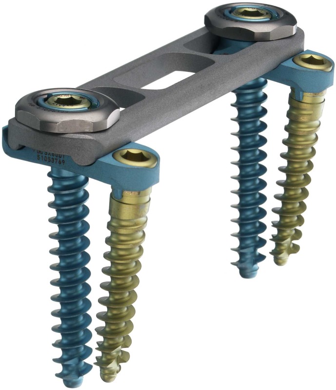
The modular anterior fixation system MACS-TL (modular anterior construct system thoracic lumbar, Aesculap, Tuttlingen, Germany) is an angular-stable implant for stabilizing the anterior section of the thoracolumbar spine after an instability due to trauma, degeneration, inflammation or neoplasm. [1] It can be inserted by an open, microsurgical (mini trans-thoracic approach [TTA]) or endoscopic approach [1, 12]. Using the twin-screw concept, it consists of a low-profile plate (less than 10 mm thick), clamping elements with nuts and locking screws, and two self-cutting, monocortically fixed screws for each adjacent vertebral body (Fig. 1). The system is constructed of titanium alloy and can be applied for both monosegmental and bisegmental stabilization. For multisegmental use, the plate is replaced by rods. The twin screws converge at an angle of 10° in the neutral position. The length of the plate varies between 45 mm and 100 mm. The system allows distraction of the bridged region.
Fig. 1.
MACS-TL system
Grupp et al. [6] dynamically tested the mechanical properties of the MACS-TL system in a corpectomy model and found relatively high stiffness and strength in comparison with other implants. Schultheiss et al. [12] performed biomechanical in vitro tests in six human cadaver specimens ranging from T10 to L2. After a corpectomy of T12, the MACS-TL system was mounted on the specimen, while a wooden dowel simulated a bone graft. Using a universal spine tester [16], they loaded the specimens with pure moments of 3.75 Nm in flexion/extension, left and right lateral bending and left and right axial rotation. Stabilizing effects were found to be higher than those achieved with dorsal stabilizing systems.
Creating a finite element model of such a complicated structure as the lumbar spine requires several simplifications and assumptions concerning geometry, material properties of the different tissues, contact behavior of joints, and acting loads that may strongly influence the results. Thus, validation of the model is mandatory. After the validation process, the computer model also allows the calculation of parameters that cannot be measured, e.g., stresses in the vertebral body.
The aim of this study was to insert successively a posteriorly (internal spinal fixation device) and an anteriorly (MACS-TL system) fixed implant in our validated finite element model of the lumbar spine and to analytically compare the biomechanical behavior of the two implant systems. We hypothesized that, due to the MACS-TL implant, intersegmental rotation in the bridged region is more reduced, while intradiscal pressure in the adjacent caudal disc, maximum stresses in the bridged vertebra and facet joint forces are higher than after implantation of internal fixators.
Materials and methods
A three-dimensional osseoligamentous nonlinear finite element model was created to simulate the lumbar spine. The finite element mesh of the vertebrae is based on the L4 model created by Smit [14]. The geometry of the vertebrae was adapted using data from CT and the literature. In order to get reasonable element side ratios for the chosen element mesh, the outer element layer consisted of cortical and cancellous bone. Therefore, the elastic modulus for this layer was chosen to represent the combination of both materials (Table 1). The nuclei pulposi were modelled as incompressible fluid-filled cavities, and volume elements with superimposed spring elements were used for the annuli fibrosi. The latter represent the disc fibers. Fiber stiffness increased linearly from the border to the nucleus outwards. The outermost fibers had a stiffness of 14.1 N/mm and the innermost fibers one of 5.1 N/mm. The facet joints were assumed to be frictionless, had a gap of 0.5 mm, and could only transmit compressive force. The capsule of the facet joints and the six ligaments of the lumbar spine were included in the finite element model. The mostly nonlinear material properties of all tissues (Tables 1 and 2) were taken from the literature [4, 5, 13]. The intact model was validated on the basis of experimental data from in vitro measurements [9, 10], and a high degree of conformity was found. It is described in detail elsewhere [19, 21].
Table 1.
Material properties of different components
| Material | Elastic modulus (MPa) | Poisson ratio (-) |
|---|---|---|
| Outer element layer of vertebral body (cortical / cancellous bone) | 5,000 | 0.3 |
| Cancellous bone | 500 | 0.2 |
| Posterior bony elements | 3,500 | 0.25 |
| Bone graft | 1,000 | 0.3 |
| Annulus fibrosus (ground substance) | 3.15 | 0.45 |
| MACS-TL system (titanium alloy) | 110,000 | 0.3 |
| Internal fixation device (implant steel) | 210,000 | 0.3 |
Table 2.
Ligament stiffnesses for three different strain ranges ( Lig ligamentum, Long longitudinale)
| Ligaments | Stiffness (N/mm) |
Strains between (%) |
Stiffness (N/mm) |
Strains between (%) |
Stiffness (N/mm) |
Strains higher than (%) |
|---|---|---|---|---|---|---|
| Lig. long. anterius | 347 | 0–12.2 | 787 | 12.2–20.3 | 1,864 | 20.3 |
| Lig. interspinale | 1.4 | 0–13.9 | 1.5 | 13.9–20 | 14.7 | 20 |
| Lig. capsulare | 36 | 0–25 | 159 | 25–30 | 384 | 30 |
| Lig. intertransversarium | 0.3 | 0–18.2 | 1.8 | 18.2–23.3 | 10.7 | 23.3 |
| Lig. flavum | 7.7 | 0–5.9 | 9.6 | 5.9–49 | 58.2 | 49 |
| Lig. long. posterius | 29.5 | 0–11.1 | 61.7 | 11.1–23 | 236 | 23 |
| Lig. supraspinale | 2.5 | 0–20 | 5.3 | 20–25 | 34 | 25 |
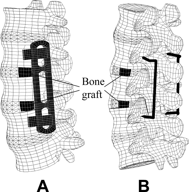
A bisegmental MACS-TL system and bone grafts were integrated in the intact model to simulate treatment of a degenerative instability (Fig. 2a). The bone grafts were inserted with their long axes in the frontal plane. A small window was cut in the left lateral annulus and the nucleus pulposus removed to allow insertion of a graft. The bone grafts were assumed to be homogeneous with an elastic modulus of 1,000 MPa. Loose contact with high friction was assumed between the graft and the adjacent vertebral body. Thus, no tensile forces could be transmitted at the interface, simulating the postoperative situation. In an additional study, the MACS-TL system was replaced by a bisegmental internal spinal fixation device (Fig. 2b) [20]. Both implants bridged the L3 vertebra, and the bridged spinal region was compressed by shortening the longitudinal part of the implants by 0.25 mm. This simulates a reduction of the distance between the screws.
Fig. 2.
Outer finite element mesh of the lumbar spine with MACS-TL system and bone grafts ( a) and with internal fixation device and bone grafts ( b)
The following physiological loading cases were studied for the intact model and the two implants: standing, 30° flexion (forward bending), 15° extension of the lumbar spine, and 6° torsion (axial rotation). For all loading cases studied, the overall inclination or rotation of the lumbar spine was predetermined and unrelated to the implant. This means that a reduced deformability in one segment (e.g., due to an implant) has to be compensated in the other segments of the lumbar spine. For standing, flexion and extension of the lumbar spine, the loads suggested by Wilke et al. [18] were applied (Table 3). Standing was simulated by applying a vertical force of 260 N, representing the weight of the upper body and a follower load of 200 N representing the stabilizing effect of the local muscle forces [7, 10]. The global dorsal muscle force representing the erector spinae was applied to counterbalance the moment caused by the upper body weight [19]. The muscle force differed slightly for the two implant types (Table 3). The angle in the sagittal plane between the upper endplate of the L1 vertebra and the lower endplate of the L5 vertebra was constant for standing and assumed to be the same as for the unloaded lumbar spine. Extension and flexion of the lumbar spine were simulated by applying the same vertical force and follower load as for standing, plus an additional force of 50 N in the rectus abdominis [18]. The force in the erector spinae was calculated to achieve an extension angle of 15° and a flexion angle of 30°, respectively. After insertion of an implant, the necessary force in the erector spinae to achieve the desired spinal deformation was strongly increased for extension and drastically reduced for flexion (Table 3). Axial rotation (torsion) was simulated by applying a pure torsional moment with a superimposed follower load of 460 N. Thus, the axial load was the same as for the other loading cases. The calculated intradiscal pressures in L4/5 for the intact lumbar spine were close to those measured in vivo for all four loading cases studied [8, 15, 17].
Table 3.
Applied loads for the different loading cases
| Activity | Upper body weight (N) | Follower load (N) | Force in rectus abdominis (N) | Force in erector spinae (N) | ||
|---|---|---|---|---|---|---|
| - | Intact | Fixators | MACS-TL | |||
| Standing | 260 | 200 | 0 | 167 | 179 | 183 |
| Flexion | 260 | 200 | 50 | 888 | 149 | 77 |
| Extension | 260 | 200 | 50 | 78 | 277 | 308 |
| Torsion | 0 | 460 | 0 | 0 | 0 | 0 |
The following output parameters were chosen: intersegmental rotation angle relative to the unloaded lumbar spine; pressure in the nucleus of the discs L1/2 and L4/5; maximum von Mises equivalent stress in the contact area of the graft to the lower endplate of the bridged L3 vertebra; and facet joint forces. Intersegmental rotation angles and intradiscal pressure can also be measured in in vitro studies. Thus, these parameters allow an estimation about the quality of the model. High intersegmental rotation in the bridged region leads to high relative motion between bone graft and adjacent vertebral body and may thus prevent fusion. High stresses in the vertebral endplate may lead to graft subsidence and reduced lumbar lordosis, while high facet joint forces may cause degeneration and pain. Results were compared for the intact model, the model with the MACS-TL implant system and bone grafts, and the model with a bisegmental internal spinal fixation device and bone grafts [20].
Results
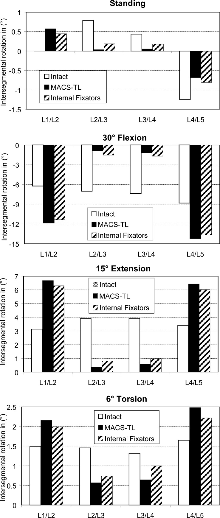
Intersegmental rotations (Fig. 3) are small for the loading case of standing, since the sum of the four intersegmental rotations of the lumbar spine is zero. The highest absolute values are predicted for the L4/L5 segment. Intersegmental rotations are small in the bridged segments (L2/L3 and L3/L4) after insertion of an implant. There are no appreciable differences between the results for the anterior and posterior implants. The absolute values of intersegmental rotation for 30° flexion, 15° extension, and 6° torsion of the lumbar spine are considerably reduced in the bridged region after insertion of an implant. The reduction is always greater for the anteriorly fixed MACS-TL system than for the internal fixation device. Since the overall deformation of the lumbar spine was the same for the intact and the implanted spine, the outer segments (L1/L2 and L4/L5) underwent greater deformations after insertion of an implant. The hypothesis that the intersegmental rotation in the bridged region is more reduced by the MACS-TL system than by the internal fixator could be corroborated.
Fig. 3.
Intersegmental rotation in the loading plane at the different levels for standing ( top), 30°flexion, 15° extension and 6° torsion ( bottom). Results are shown for the intact lumbar spine, after insertion of a MACS-TL system, and after implantation of paired internal fixators. The values represent the angular variations relative to the unloaded spine
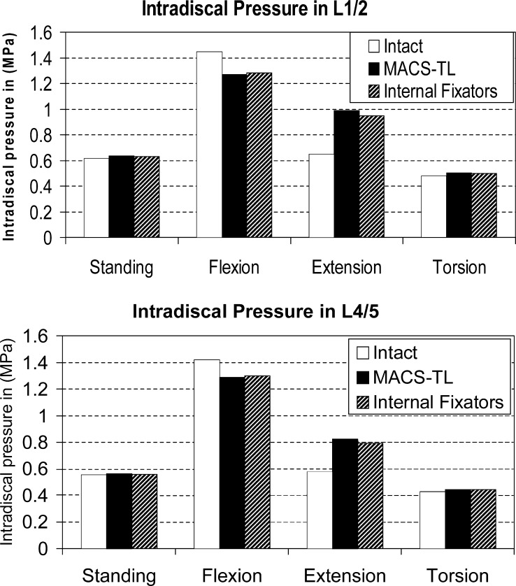
Compared with the intact spine, intradiscal pressures in the discs below and above an implant are slightly decreased for flexion, increased for extension and nearly unchanged for standing and torsion (Fig. 4). Intradiscal pressure is mostly slightly higher in the disc L1/2 than in L4/5. The differences between anteriorly and posteriorly fixed implants are negligible. Thus, our hypothesis that the intradiscal pressure is higher after implanting the MACS-TL system than after insertion of an internal fixation device could not be corroborated.
Fig. 4.
Intradiscal pressure in the L1/2 ( top) and L4/5 disc ( bottom) for the intact lumbar spine, after insertion of a MACS-TL implant, and after implantation of an internal fixation device
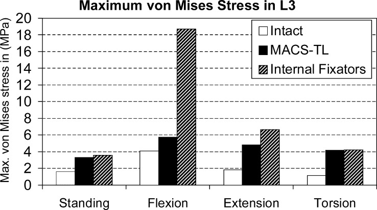
Implants increase maximum von Mises stresses in the bridged L3 vertebra in the region of contact with the bone graft for all loading cases studied (Fig. 5). For flexion, the stresses are strongly increased by an internal fixation device but only slightly increased by the MACS-TL implant. For extension, the increase in maximum von Mises stresses is also more pronounced for the internal fixators than for the MACS-TL implant. For standing and torsion, both implants have nearly the same effect on maximum stresses. The hypothesis that the maximum stress in the L3 vertebra is higher for the MACS-TL implant than for the internal fixators could not be corroborated.
Fig. 5.
Maximum von Mises stress at the bridged L3 vertebra in the region of contact with the graft in different loading cases for the intact lumbar spine and after insertion of a posterior and an anterior implant
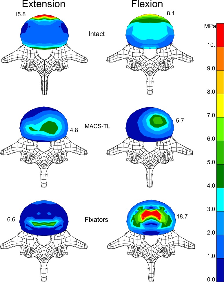
The highest stresses in the endplates of the bridged vertebral body are calculated for the anterior rim of the annulus close to the anterior longitudinal ligament for the intact model and the loading cases of flexion and extension (Fig. 6). After insertion of an implant, stresses are highest in the region of contact between endplate and bone graft. For the fixators, stresses are symmetrically distributed and highest at the posterior side of the graft for extension and at the anterior side for flexion. After insertion of the MACS-TL implant, the stress is unsymmetrically distributed with the highest stress values on the left side where the implant is fixed.
Fig. 6.
Distribution of von Mises stresses in the lower endplate of L3 for extension ( left) and flexion ( right). Stress distribution is shown for the intact model ( top), after implantation of a MACS-TL system ( middle), and after insertion of an internal fixation device ( bottom). Maximum stress value for each endplate is also given
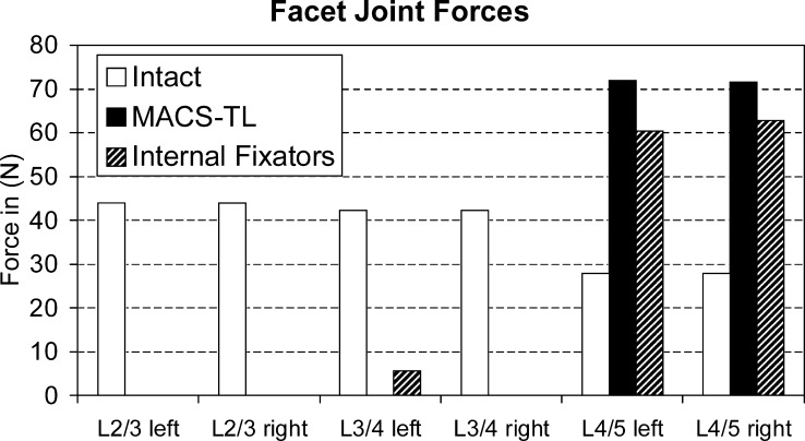
For standing and flexion, contact forces in the facet joints are always very low, except at L4/5 after insertion of an implant. Flexion was found to be associated with a facet joint force of 63 N at that level for the model with internal fixators and 85 N for the model with the MACS-TL implant. For extension, the force at L4/L5 increases from 35 N for the intact lumbar spine to 109 N for the model with internal fixators and 111 N for the model with the MACS-TL implant. For torsion, the force in the left facet joint corresponds to right axial rotation and vice versa. For this loading case, the force in the ipsilateral facet joint is always zero. Both implants strongly reduce contralateral facet joint forces in the bridged region for torsion (Fig. 7). For the segment below the implants, the contact forces in the facet joints are increased after insertion of an implant. The force increase is slightly more pronounced by the MACS-TL implant than by the internal fixators. Our hypothesis that the facet joint forces are higher after implantation of the MACS-TL system than they are after implantation of the internal fixators was corroborated for flexion and extension and for axial rotation at the level L4/5.
Fig. 7.
Compressive forces in the contralateral facet joint of the different segments for left and right axial rotation. The forces are compared for the intact lumbar spine and after insertion of a MACS-TL system and an internal fixation device. The side of the contralateral facet joint is given on the x -axis
Discussion
We studied the mechanical effects of an anterior and a posterior implant for stabilizing the spine using a finite element (FE) model of the lumbar spine. Due to the necessary simplifications and assumptions concerning the geometry, material properties of the different tissues, contact behavior, and applied loads, the results of the calculations represent trends rather than precise values. This is especially true for stresses in the bridged vertebra and forces in the facet joints.
The bone grafts were assumed to be homogeneous and to fit exactly into the space between the vertebral bodies, which is normally not the case. However, each graft is different and the exact material and geometrical properties are not known. Contact with high friction was assumed between graft and adjacent vertebral bodies. Thus, no tensile force could be transferred by the graft.
For each of the loading cases examined, the upper endplate of the L1 vertebra was assumed to be at a certain predetermined angle relative to the fixed lower endplate of the L5 vertebra. This means that the overall deformation of the lumbar spine is constant for each loading case. Thus, the reduced deformation in the region bridged by an implant is offset by increased deformation of the adjacent segments. This increase strongly depends on the number of non-bridged segments in the FE model. The greater the number, the weaker the influence and vice versa. Therefore, the results for the adjacent segments show only trends, and the absolute values should be handled with caution. A predetermined load instead of a predetermined deformation would probably have shown that the implant had only a minor influence on the adjacent segments [9]. In a patient, spinal deformation is often predetermined by the aimed activity. The spinal range of motion will be reduced after stabilizing a segment with an implant, thus suggesting a higher maximum spinal load. However, there are marked inter-individual differences in the spinal range of motion, and patients with a spinal implant will bend their spine less than they could prior to surgery. This renders it difficult to determine whether a stabilizing implant has a detrimental biomechanical effect on the adjacent segments.
An implant reduced intersegmental rotation in the bridged region (Fig. 3). The reduction was more pronounced for the MACS-TL system than for the internal fixator. A smaller intersegmental rotation should also cause smaller relative motion at the interface between bone graft and vertebral body and thus be advantageous concerning fusion. Schultheiss et al. [12] simulated the different situation of strut grafting after corpectomy of a fractured T12 vertebra, applied pure moments of 3.75 Nm and measured range of motion and neutral zone in the bridged region. They experimentally demonstrated higher stabilizing effects for the MACS-TL implant than for dorsal stabilizing systems. Our analytical results show the same trend.
The type of implant has only a slight effect on intradiscal pressure. After insertion of an implant, intradiscal pressure decreased for flexion and increased only for extension. Compared with the intact spine, it was unchanged for standing and torsion. Thus, our results do not support the hypothesis that degeneration of the discs adjacent to a fused segment is caused mechanically.
Motion of the spine occurs mainly in the discs. An intact disc transfers the load from one vertebral body to the next with a relatively even stress distribution over its cross-sectional area. The high stresses at the anterior rim of the vertebral body for extension are mainly caused by the force in the anterior longitudinal ligament. A bone graft has a smaller cross section and is harder than a disc, which causes higher stress peaks in the contact area, especially at the circumference of the graft. A stabilizing implant exerts resistance against the deformation of the bridged region and protects the bridged vertebral body against high loads. The resistance increases with increasing stiffness of the longitudinal implant part and with decreasing distance from the deformation site, i.e., the discs. The MACS-TL system is fixed close to the vertebral body and has high axial stiffness. The longitudinal rod of an internal fixator is more distant from the vertebral body, and the bending stiffness of the pedicle screws is relatively low. Thus, an anteriorly fixed MACS-TL system exerts higher resistance against spinal deformation than does the posteriorly fixed internal fixation device. This is the main reason why maximum stresses in the bridged vertebral body are lower after insertion of a MACS-TL system than after implantation of an internal fixation device (Figs. 5 and 6).
The pretension in the fixators and the MACS-TL system was simulated by predefined shortening of the longitudinal rods and the plate respectively. It was not simulated by introducing a pretension force. Since pretension has a great impact on stress distribution in the bridged region [11], the absolute values should be regarded with caution.
For torsion, compressive forces in the contralateral facet joint of the segment adjacent to the implant are higher for the MACS-TL implant than for the internal fixation device (Fig. 7). This corresponds well with the greater intersegmental rotation for the MACS-TL system at that level.
Conclusions
Both anteriorly and posteriorly fixed implants are clinically successful. They both considerably reduce intersegmental rotation in the bridged region, though the reduction is more pronounced for the MACS-TL implant than for the internal fixation device. The two implant types have nearly the same influence on intradiscal pressure in the adjacent disc. However, they were found to differ significantly with respect to maximum stresses in the bridged vertebra. Since the MACS-TL system is fixed closer to the vertebral body and thus has a stronger effect on the overall system stiffness, maximum stresses in the endplate of the bridged vertebra are lower for flexion and extension than those seen after implanting an internal fixation device. After insertion of internal fixators, very high maximum stresses are predicted for flexion; thus patients who are treated with internal fixators should avoid excessive flexion in the period immediately after surgery, to reduce the risk of graft subsidence.
Acknowledgements
The original element mesh of the L4 vertebra was created by Smit. It is available on the internet at the ISB Finite Element Repository managed by the Instituti Ortopedici Rizzoli. Finite element analyses were performed at the Norddeutscher Verbund für Hoch- und Höchstleistungsrechnen (HLRN) and Zentraleinrichtung Rechenzentrum Berlin (ZRZ). The authors thank M. Fehrmann for assistance with the finite element calculations and Dr. J. Weirowski for editorial assistance. Funding for this study was obtained from the Deutsche Forschungsgemeinschaft, Bonn, Germany (Ro 581/13–3).
References
- 1.Beisse R, Potulski M, Beger J, Buhren V (2002) Entwicklung und klinischer Einsatz einer thorakoskopisch implantierbaren Rahmenplatte zur Behandlung thorakolumbaler Frakturen und Instabilitäten. Orthopäde 31:413–422 [DOI] [PubMed]
- 2.Bogduk Spine. 1992;17:897. doi: 10.1097/00007632-199208000-00007. [DOI] [PubMed] [Google Scholar]
- 3.Calisse J Biomech. 1999;32:727. doi: 10.1016/s0021-9290(99)00052-4. [DOI] [PubMed] [Google Scholar]
- 4.Goel Spine. 1995;20:689. [PubMed] [Google Scholar]
- 5.Goel J Biomech Eng. 1995;117:266. doi: 10.1115/1.2794180. [DOI] [PubMed] [Google Scholar]
- 6.Grupp TM, Beisse R, Potulski M, Marnay T, Beger J, Blomer W (2002) Mechanische Testung der Implantateigenschaften eines thorakoskopisch implantierbaren ventralen Wirbelsäulenstabilisierungssystems. Orthopäde 31:406–412 [DOI] [PubMed]
- 7.Patwardhan Spine. 1999;24:1003. doi: 10.1097/00007632-199905150-00014. [DOI] [PubMed] [Google Scholar]
- 8.Rohlmann Ergonomics. 2001;44:781. doi: 10.1080/00140130120943. [DOI] [PubMed] [Google Scholar]
- 9.Rohlmann Eur Spine J. 2001;10:301. doi: 10.1007/s005860100295. [DOI] [PMC free article] [PubMed] [Google Scholar]
- 10.Rohlmann Spine. 2001;26:E557. doi: 10.1097/00007632-200112150-00014. [DOI] [PubMed] [Google Scholar]
- 11.Rohlmann BIOmaterialien. 2003;4:236. [Google Scholar]
- 12.Schultheiss M, Wilke HJ, Claes L, Kinzl L, Hartwig E (2002) MACS-TL-twin-screw. Ein neues thorakoskopisch implantierbares Stabilisationssystem zur Behandlung von Wirbelfrakturen—Implantatdesign, Implantationstechnik und In-vitro-Testung. Orthopäde 31:362–367 [DOI] [PubMed]
- 13.Shirazi-Adl Spine. 1986;11:914. doi: 10.1097/00007632-198611000-00012. [DOI] [PubMed] [Google Scholar]
- 14.Smit T (1996) The mechanical significance of the trabecular bone architecture in a human vertebra. Shaker, Aachen, Germany
- 15.Wilke HJ, Neef P, Hinz B, Seidel H, Claes L (2001) Intradiscal pressure together with anthropometric data—a data set for the validation of models. Clin Biomech (Bristol, Avon) 16:S111–126 [DOI] [PubMed]
- 16.WilkeEur Spine J 19943917874556 [Google Scholar]
- 17.Wilke Spine. 1999;24:755. doi: 10.1097/00007632-199904150-00005. [DOI] [PubMed] [Google Scholar]
- 18.WilkeSpine 200328258514652475 [Google Scholar]
- 19.Zander T, Rohlmann A, Calisse J, Bergmann G (2001) Estimation of muscle forces in the lumbar spine during upper-body inclination. Clin Biomech (Bristol, Avon) 16:S73–80 [DOI] [PubMed]
- 20.Zander T, Rohlmann A, Klöckner C, Bergmann G (2002) Comparison of the mechanical behavior of the lumbar spine following mono- and bisegmental stabilization. Clin Biomech (Bristol, Avon) 17:439–445 [DOI] [PubMed]
- 21.Zander J Biomech. 2002;35:491. doi: 10.1016/s0021-9290(01)00235-4. [DOI] [PubMed] [Google Scholar]


