

Abstract
We describe the design and performance of a hand-held actively stabilized tool to increase accuracy in micro-surgery or other precision manipulation. It removes involuntary motion such as tremor by actuating the tip to counteract the effect of the undesired handle motion. The key components are a three-degree-of-freedom piezoelectric manipulator that has 400 μm range of motion, 1 N force capability, and bandwidth over 100 Hz, and an optical position measurement subsystem that acquires the tool pose with 4 μm resolution at 2000 samples/s. A control system using these components attenuates hand motion by at least 15 dB (a fivefold reduction). By considering the effect of the frequency response of Micron on the human visual feedback loop, we have developed a filter that reduces unintentional motion, yet preserves intuitive eye-hand coordination. We evaluated the effectiveness of Micron by measuring the accuracy of the human/machine system in three simple manipulation tasks. Handheld testing by three eye surgeons and three non-surgeons showed a reduction in position error of between 32% and 52%, depending on the error metric.
Index Terms: Medical robotics, optical tracking, piezoelectric devices, compensation
I. Introduction
Normal hand tremor under microsurgical conditions is typically several hundred microns peak-to-peak [1, 2], yet from medical necessity surgeons routinely manipulate much smaller structures (such as the 10 μm thick retinal internal limiting membrane [3]) using handheld tools. Though such feats of dexterity are remarkable, it seems likely that some technical means for stabilizing hand motion during microsurgery would allow more consistent outcomes for existing procedures, and (more importantly) allow the development of new procedures currently made impractical by the accuracy limits of unaided manipulation [4, 5]. We have concentrated on applications to eye surgery due to the high accuracy required, but such technologies would likely be valuable in other areas of surgery [6] and for other applications such as biological research [7] or industrial assembly tasks [8]. Before discussing the state of the art we must review relevant properties of the human component in an aided manipulation system: tremor characteristics, and human-in-the-loop dynamics.
A. Tremor Characteristics
For simplicity we use tremor to mean any involuntary hand motion that creates position error. This differs somewhat from medical usage, where tremor is defined as a rapid quasi-periodic motion [9]. Furthermore, our concern is with the position error at the tip of a small tool manipulated using visual feedback under a microscope. Tremor characteristics may differ if there are changes in visual feedback or target motion amplitude [10].
Fig. 1 shows typical motion when a subject tries to hold a tool tip stationary (as in the experiments in §III). In addition to the high-frequency quasi-periodic motion, there is also drift or wander (slow trends) and jerk (sporadic fast jumps). Whatever terminology is used, it is necessary to suppress all these motions to achieve useful stabilization.
Fig. 1.

Tremor signal with identified features. Low-frequency wander and non-periodic jerk components dominate the peak-to-peak amplitude.
Fig. 2 shows the spectrum of the position error resulting from averaging the power spectrum across 54 trials using six subjects (27 minutes of data (§III.A)), then further averaging across 50 logarithmically-spaced frequency bins [11].
Fig. 2.

Spectra of position error and acceleration during “hold still” task. The acceleration spectrum shows a 10 Hz tremor peak, yet in the position spectrum, low-frequency error dwarfs this 10 Hz peak, leveling off in the band where visual feedback is effective. In this visual feedback band, error is greater in the vertical (visual depth) direction.
In physiology research, tremor is generally measured using an accelerometer, and then characterized by the peaks of the acceleration spectrum [11], so for comparison, we have also plotted the acceleration spectrum (obtained by multiplying the position spectrum by the frequency response of a double differentiation). Although acceleration does have physical meaning, the prominence of the 10 Hz peak in the acceleration spectrum is arguably an artifact of the choice to analyze acceleration, with its implicit emphasis on high-frequency dynamics. This acceleration peak (and the subsequent steeper lowpass rolloff in position error) result primarily from the biomechanical resonance of the hand [12], and give the acceleration signal its quasi-periodic character. The implicit high-frequency emphasis of acceleration suits the medical definition of tremor, and accelerometers are convenient for medical diagnosis, but this prevalent practice in the tremor literature [11–14] discards important information about normal involuntary hand motion, and initially led us astray in defining Micron’s performance requirements (§I.D).
The bandwidth of human eye-hand feedback generally lies between 0.5 Hz to 2 Hz (§I.B). It is only below this critical frequency that eye-hand feedback becomes effective. This visual feedback contributes to the shift to a nearly flat position spectrum that begins below 0.5 Hz. The microscope view is vertical, so the user relies on depth perception to discern motion in this direction. At low frequencies, vertical error is twice as large as the horizontal error, apparently due to the inferiority of depth perception (§III.B.1).
Fig. 3 shows the probability distribution of the magnitude of the tip velocity vector (same data as Fig. 2). At each speed, the curve shows the fraction of the samples having that speed or lower; for example, 90% of samples are below 2 mm/s.
Fig. 3.

Probability distribution of the tool tip velocity during “hold still” task. This is the empirical Cumulative Distribution Function (CDF), plotted with a logarithmic vertical scale to show the detail in both distribution tails. A Gaussian CDF would be a straight line on these axes, so the curvature shows strong skewing.
B. Human-in-the-Loop Dynamics
We cannot design manipulation aids without considering that the aid is inside the eye-hand feedback loop. Although reducing a human to a linear system obviously neglects many details, this approach has been successfully used for over 50 years in the design of aircraft control systems and flight instrumentation [15]. Fig. 4 shows a simple human-in-the-loop feedback model. The operator internally develops a goal position RH, then uses visual feedback to move the hand to the desired position. The human “controller” CH functions well with a certain range of dynamics GH. An introduced manipulation aid transduces the hand motion X into some tool motion Y. If GA (the aid dynamics) is poorly chosen, it will destabilize the overall eye-hand feedback. Of particular concern is the time delay or phase lag at the loop critical frequency (where the open-loop gain drops below unity).
Fig. 4.

Simple feedback model of the human-in-the-loop system with a manipulation aid. Tremor is modeled as a disturbance DH added to the hand motion. Eye-hand feedback acts to minimize the effect of this disturbance. GA is the dynamic contribution of the aid system, which may destabilize the overall eye-hand feedback.
Human performance studies have shown that the Bode plot of the human frequency response exhibits a 45° intercept at the loop critical frequency [16], generating the same sort of frequency response as a classical feedback controller. It is only near the critical frequency that the human controller is subject to the constraints of loop stability; at lower frequencies there is more individual and temporal variation of human control behavior. The critical frequency of the human eye-hand feedback loop varies somewhat by task, but is generally found to be in the range of 0.5 to 2 Hz [17, 18].
C. State of the Art in Microsurgical Manipulation Aids
Table I summarizes the state of the art in manipulation aids for microsurgery such as eye surgery. First we classify systems (columns), and then consider characteristics (rows).
Table I.
Comparison of Microsurgery Manipulation Aids
| Unaided | Master/slave | Cooperative | Micron | |
|---|---|---|---|---|
| Motion scaling: | No | Yes | No | Yes |
| Workspace intrusion: | No | Slave arm & master | Arm | Active tool, sensor sightlines |
| Force feedback: | 1:1 | Research area | Yes (superimposed on damping) | 1:1 |
| Set and forget hold: | No | Yes | Yes | No |
| Features: | Current practice | Could combine all of the above features, telemedicine | Inexpensive position-output actuators and simple control | Hand-held operation improves user acceptance and safety, mechanical simplicity |
| Challenges/costs: | Tremor limits accuracy & repeatability | Unproven force feedback performance/greatest mechanical and control complexity (high cost) | Dexterity fundamentally limited by force → rate user interface and low control bandwidth | Manipulator size and range, high bandwidth control/measurement subsystem cost |
The most common approach to surgical robots has been master-slave teleoperation [19], which enables improved accuracy through motion scaling and low-pass filtering of tremor. This technology has been brought into the routine practice of endoscopic surgery by the da Vinci robot (Intuitive Surgical) [20]. Although not designed for eye surgery, the availability of da Vinci has led to investigations of its applicability [21]; kinematic limitations have led to the development of a prototype micropositioner accessory [22]. Other investigations into teleoperated eye surgery have generally involved purpose-built hardware [23–25]. Among such systems, we choose the JPL RAMS robot [26] as the exemplar for the table because its complete implementation allows performance to be compared.
Another approach is cooperative control, where the operator guides the end of a robot arm using an attached grip that senses the force applied by the hand. The arm’s passive stiffness prevents tremor from disturbing the tool position. Measured hand force is converted into an arm velocity goal, which is implicitly low-pass filtered by the 9dynamics of the arm. This creates the effect of viscous damping that attenuates tremor. We choose the steady-hand robot [27, 28] as our exemplar, since it was developed for eye surgery.
In the Micron approach, a handheld tool actuates its own tip to cancel tremor. This concept is analogous to the optical image stabilization in a handheld camera, and uses no robot arm. The greater stability of the tool tip compared to the handle is entirely due to the active stabilization of the measured tip position with respect to a goal point expressed in a fixed coordinate system.
1) Manipulation Aid Characteristics
We now consider system characteristics (rows in Table I). A common technique for reducing the effect of tremor is motion scaling: causing the motion at the output to be a fraction of the hand motion. The operator then makes larger motions with greater relative accuracy. Scaling preserves human-in-the-loop stability, since the flat frequency response need not add delay. Because of its rigid connection between input and output, cooperative manipulation cannot support motion scaling. In effect, the damping of cooperative manipulation attenuates tremor by low-pass filtration alone. Because of the prompt force-feedback to the hand, this does not destabilize eye-hand feedback as it would in a position-input system (§II.F), but it limits voluntary control bandwidth.
Workspace intrusion refers to the additional hardware or other ergonomic constraints added to the surgeon’s workspace by the aid system. This is a concern because there is a great deal of other equipment also in use, most importantly the surgical microscope, which must have a clear sight-line. A slave arm or cooperative arm necessarily intrudes into the workspace, and Micron introduces optical constraints with its requirement for a sensor sightline. In steady-hand cooperative manipulation, the surgeon directly grasps the tool, preserving this familiar interface. In master/slave operation, the input device has no mechanical connection to the output. A surgeon using da Vinci works in a virtual environment entirely separated from the patient, which enables telemedicine, and is also beneficial for local use due to the unfavorable ergonomics of conventional lapar33oscopy. The situation is different in eye surgery, where the surgeon directly views the interior of the eye through the lens using a surgical microscope. The RAMS robot demonstrates that a master/slave system for eye surgery can preserve this work pattern, but then both the master and slave intrude into the surgeon’s workspace.
An aid supports force feedback if forces exerted on the tool can be directly felt by the operator. Micron preserves the 1:1 force feedback of unaided operation, but, having no mechanical ground, it is fundamentally incapable of providing scaled force feedback. In microsurgery, 1:1 force feedback is of limited value because the tool tip is small and the tissue is soft, so an imperceptible force can create pressure high enough to cause damage. One study has found that in vitreoretinal surgery, 75% of the time contact forces were below 7.5 mN, a level perceptible by only 19% of surgeons [29].
Scaling up such forces to be perceptible might offer a significant benefit [30]. However, force feedback in surgical robots remains an open research problem [31, 32]. The difficulty in eye surgery is increased by the need to integrate the force sensor into the intraocular portion of the 0.9 mm diameter tool shaft [33]. Master/slave control with force feedback also faces fundamental stability challenges that tend to limit force scaling to small ratios [34]. Cooperative manipulation uses force input, avoiding these stability problems, so is well suited to force feedback. Then high scaling ratios must be used so that feedback remains clear when superimposed on the hand force needed to overcome the system’s damping effect. Greater than 60:1 force scaling has been demonstrated [35].
Set-and-forget hold allows the tool to be “parked” in a fixed location so that it can serve as a “third hand.” This is easily implemented in a robotic-arm system. Micron is handheld, so it cannot support this feature.
2) Aid Comparison Summary – Advantages of Micron
Of the two robot-arm approaches, master/slave operation has potential for a desirable combination of features, but the design complexity and production cost are significant practical barriers. Cooperative systems have a clearer path to force-feedback operation, and several advantages in implementation cost and simplicity, such as the elimination of the master and the use of position output (admittance) servomechanisms, but the sluggish force-input response limits dexterity.
Compared to these robot-arm systems, the biggest advantages of Micron are intuitive operation, safety, and economy. Micron is hand-held, so can offer the same intuitive feel as a conventional unaided tool. This improves user acceptance by preserving existing surgical skills. Hand-held operation also has a safety advantage because Micron requires a far smaller range of motion than alternative systems, and because the surgeon remains in gross control of the tool motion at all times, able to quickly withdraw if the patient moves, or to finish a procedure unaided if the system fails. Micron does not need to duplicate the function of the surgeon’s arm, so is mechanically simpler, getting by with fewer degrees of freedom and a much smaller range of motion.
D. Micron Implementation Challenges
Although the Micron approach is intuitively appealing and reasonably obvious, so far as we know the only such systems to reach the stage of implementation are the various versions of Micron [36–38] and its descendant “ITrem” [39]. This is likely due to the considerable engineering challenges of achieving adequate performance in the manipulator and position measurement subsystems. Micron’s tremor suppression is entirely dependent on the control system performance, whereas in a robot arm system, the control bandwidth need only be adequate to pass the voluntary component of motion.
Micron development began 15 years ago [40]. In 2003, [41] described the first implementation of Micron that integrated a three degree-of freedom (3-DOF) manipulator and 6-DOF position sensing into a handheld instrument. During the course of this development, concurrent studies of hand motion during simulated microsurgery [1] led to the realization that in order to achieve useful accuracy improvement, motion must be suppressed at frequencies well below 10 Hz, lower than could be accurately detected with the inertial sensors in [41]. The amplitude of motion to be suppressed at these lower frequencies is also considerably larger, increasing the required range of motion. Although [41] demonstrated measurable attenuation of simulated 10 Hz tremor in bench-top tests, it had become clear that it was incapable of canceling the lower-frequency components of hand motion, and so was never developed to the point where handheld operation could be demonstrated.
This paper reports on subsequent developments that have enabled Micron to demonstrate a significant quantitative improvement in handheld accuracy. The largest single change was architectural, replacing inertial sensing and open-loop control with DC-accurate optical sensing and closed-loop control. The challenges of manipulator range and control were also substantial. We prototyped a magnetic manipulator and two other piezoelectric manipulators [36, 37] before developing the design described here, which has a range of motion six times that of [41]. Mechanical refinements also reduced problems with friction and backlash nonlinearities, fragility, and instability of kinematic parameters that necessitated frequent recalibration. Combined with the use of charge control to minimize actuator hysteresis (§II.L), and overall position feedback, the contribution of actuator error to system performance was drastically reduced, so that tremor reduction is now limited by system delay (§II.N).
Section II describes the design of the current Micron system (Fig. 5), which includes solutions to a number of integration and control issues that appeared in handheld testing, notably the design of effective cancellation filters that do not destabilize the human feedback loop (§II.F), development of ways to gracefully handle manipulator saturation (§II.I), and robust closed-loop control of the manipulator (§II.K).
Fig. 5.
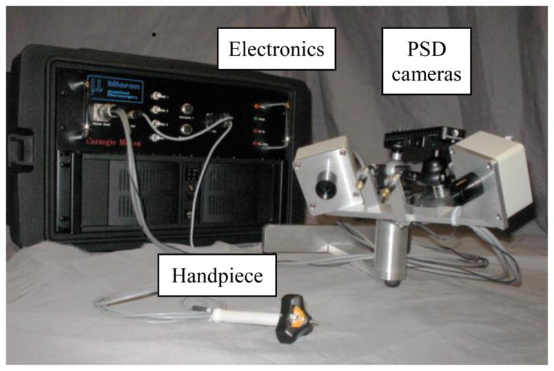
Micron system, showing tool, position sensors, and electronics.
In Section III we present experimental results from handheld testing by three trained surgeons and three non-surgeons. A three minute video provided by the authors shows Micron operation and experimental results (available at http://ieeexplore.ieee.org and http://youtu.be/6Vt81EiXR5o).
II. Design
A. System Architecture
The major system components (Fig. 6) are the handpiece, optical tracking system, custom driver and signal conditioning electronics, data acquisition cards, and a PC that runs real-time LabVIEW control software. Optical measurement determines the 6-DOF pose of the handgrip and tool. A feedback loop running at 2 kHz servos the tool tip to a goal position that is computed based on the measured hand motion. To achieve the manipulation accuracy that Micron makes possible, the operator must have some high-power magnifier, but Micron does not require any integration with microscope optics.
Fig. 6.

Micron system architecture. The handpiece contains the manipulator (which actuates the tip to cancel hand motion) and mechanically coupled LEDs (for position measurement by PSD cameras). Driver and signal conditioning electronics interface these components to a controller PC.
B. Handpiece Design
The handpiece design packages the manipulator and position measurement components into a small, lightweight (40 g) handheld tool. The current design places the manipulator and LEDs in a housing of maximum diameter 50 mm, mounted on the distal end of the handgrip (Fig 7). Although wider than desired, the indented star-like shape of the housing does allow the tool to be held within 15 mm of the microscope sightline. The grip itself contains only wiring.
Fig. 7.
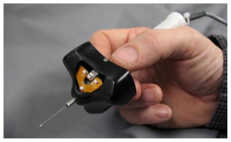
Micron handpiece, showing tool and position sensor LEDs (visible through the window in the housing).
The manipulator (Fig. 8) has a 3-DOF parallel configuration similar to ref. [42], but the actuators and flexures undergo a complex distributed deformation (Fig. 9) that does not permit a simple geometric kinematic model. The manipulator is under closed-loop control based on a direct output pose measurement, so kinematic approximation error does not compromise system accuracy (§II.H). A flex-circuit connects the electrical components, and a clear bore through the grip allows passage of tool leads such as optical fibers.
Fig. 8.
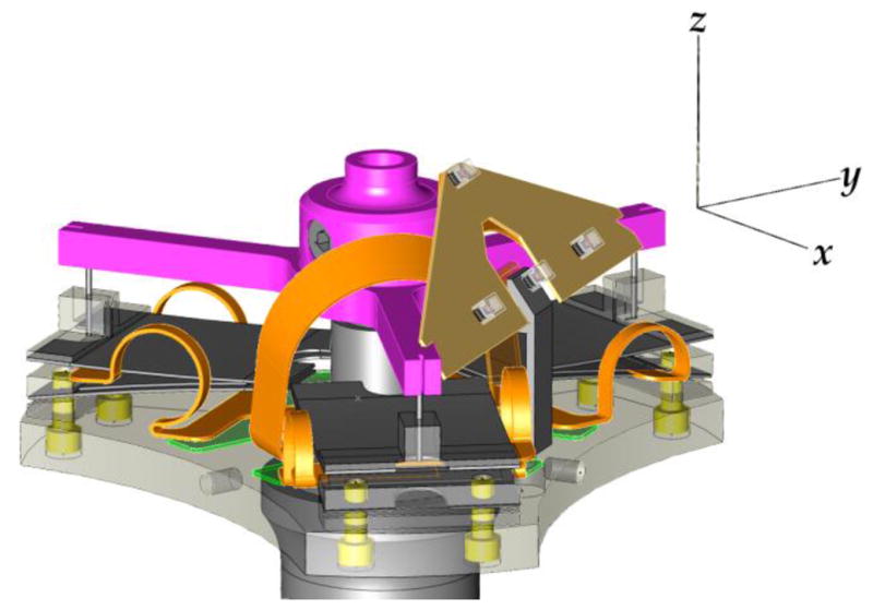
Micron three-link parallel piezoelectric manipulator. Axes show the orientation of the tip coordinate system. Each leg of the manipulator has two actuators mechanically series-connected in a folded configuration, generating approximately 600 μm of motion (detail Fig. 9). Each actuator assembly is rigidly fixed to the base plate and is connected to the star-shaped output plate by a polypropylene flexure. See also the video at http://ieeexplore.ieee.org or http://youtu.be/6Vt81EiXR5o which shows the manipulator in operation.
Fig. 9.

An exaggerated depiction of the deformation of the actuator and flexure for a single leg in the manipulator (twice the actual range of motion).
The requirement for a compact, high-bandwidth actuator with roughly 1-mm range of motion is challenging. The manipulator design depends on a unique piezoelectric bending actuator (Thunder® TH-10R, Face International Corp.) that uses a laminated metal construction to achieve a large range of motion with a stiffness greatly exceeding that of all-ceramic bending actuators. High stiffness gives the manipulator a static force output capability far in excess of microsurgical requirements, and also benefits system performance by increasing the frequency of manipulator resonances (§II.J). The piezoelectric actuators require high voltage (−240 V to +480 V) but minimal current (4 mA peak). Hysteresis and nonlinearity are reduced by controlling the total charge stored in the actuator rather than the applied voltage (§II.L).
In the current system the most important performance limits are determined by manipulator characteristics. See §I.D for comparison to the previous ref. [41] design. Greater range of motion, smaller size, and higher bandwidth would all be desirable (in decreasing order of importance); the present force (> 1 N) and slew rate (> 100 mm/s) are more than adequate. Bandwidth is discussed in §II.N.
Fig. 10 shows the volume that can be reached by a typical 40 mm tool tip. The lateral (XY) range varies with the tool length, and is significantly larger than the Z range. Though the extent of the workspace is nearly 2 mm, the largest enclosed cube is approximately 400 μm on a side.
Fig. 10.
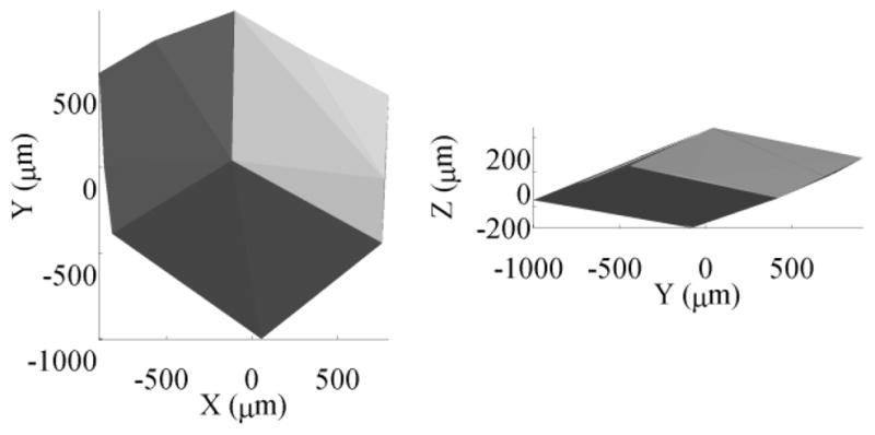
Manipulator workspace. Lateral (XY) tip motion is larger than axial (Z) motion due to the tool lever arm. This volume defines the largest disturbance that can be cancelled and limits the achievable motion scaling.
C. Coordinate Systems and Notation
The human-in-the-loop Micron system (Fig. 4) has a serial kinematic chain with two variable components: the hand and the manipulator. This establishes three useful reference frames for the coordinates of any point x: the fixed world coordinates xw, the hand coordinates xh, and the manipulator coordinates xm. The world coordinates are arbitrarily defined by the pose of the PSD cameras. The manipulator coordinate system moves with the tool. Its origin is at the tool tip and its orientation is as shown in Fig. 8. The hand coordinates are defined to be the identical to the manipulator coordinates when the manipulator is in the null position, so the origin of the hand coordinates is where the tip would be in a conventional rigid tool. If the pose of the manipulator is represented by a 4×4 linear homogenous transform Pm then this may be used to convert between coordinate systems:
In the Fig. 4 human-in-the-loop model, the response of the Micron manipulation aid is expressed as a function:
so x will be used to refer to the null tip position and y to the actual tip position (xh ≡ ym ≡ 0).
D. Position Measurement
Position measurement for Micron imposes demanding requirements for noise and latency because measurement noise creates undesirable tip motion and latency fundamentally limits canceling performance (§II.N). The measurement subsystem optically tracks the pose of both the tool and the handgrip at 2 kilosamples/s over a 4-cm workspace [43]. The major components are two position-sensitive-detector (PSD) cameras, signal conditioning electronics, infrared light-emitting diodes (IR LEDs), and an LED driver.
A PSD is a specialized large-area photodiode that makes an analog position measurement of the centroid of a light source. A lens focuses the IR light onto the PSD. A long-pass IR filter excludes much ambient light, reducing interference and shot noise. (We refer to this lens/filter/PSD combination as a camera, though it does not capture an image.) Each camera allows measurement of an LED position in two degrees of freedom. Each PSD tracks multiple LEDs simultaneously using frequency domain multiplexing. The LEDs are modulated at distinct frequencies between 8 and 20 kHz [43].
Two separated PSD cameras allow each LED position to be triangulated in three dimensions. The manipulator pose Pm is recovered from the positions of a triad of LEDs mounted on the tool holder [44]. Because the manipulator has only three degrees of freedom, the hand pose Ph can be reconstructed from the tool pose using only one additional LED mounted on the handle. The hand pose defines xw, the null tip position.
The measurement noise of the LED position is white, with vector amplitude of 0.74 μm RMS in the full 1 kHz measurement bandwidth. The tip position yw is by definition the origin of the manipulator coordinates, but achieving this desired reference requires calibration of the tip location with respect to the LEDs (using a pivot calibration procedure). Since the LEDs are offset from the tip, error in the pose orientation creates a lateral error in the tip position proportional to this offset. With a typical tool length the resulting tip noise is 5.7 μm RMS at full bandwidth. Although the control loop runs at the 2 kilosamples/s measurement rate, the control bandwidth is considerably less, about 100 Hz (§II.N), and this is also the bandwidth of the 200 samples/s data collection in §III. The tip position noise in this reduced 100 Hz bandwidth is 1.8 μm RMS.
E. Small-Signal Model
To understand the operation of Micron, first consider a generic small-signal model of a feedback system with disturbance (Fig. 11). In Micron the manipulator generates a motion that is mechanically added to the hand tremor and other disturbances D(s) to generate the tip motion Y(s). A suitably chosen controller C(s) can compensate for the manipulator dynamics G(s), driving the tip to the goal position R(s). This negative feedback subtracts out the disturbances without requiring any direct measurement of D(s).
Fig. 11.

Position servo loop small-signal model with disturbance. This servo loop stabilizes the tip position without any direct measurement of hand motion, canceling disturbance from any source.
The Micron small-signal model (Fig. 12) includes this position servo loop (Fig. 11) as a component. In the Fig. 4 human-in-the-loop system, a manipulation aid such as Micron converts hand motion X into tool motion Y. The hand motion X is a combination of the human’s desired motion RH and the tremor disturbance DH. The cancellation filter H(s) computes R(s), the reference for the position servo loop, from a measurement of this hand motion. Conceptually R(s) is an estimate of the human reference position RH. If H(s) recovered RH perfectly and the position servo loop tracked R(s) perfectly, then Y(s) = RH. It is inherent in Micron’s handheld implementation that there is a unity-gain feed-forward path from input to output (X to Y). Non-intuitively, this mechanical connection sums the desired motion RH into the disturbance that the position servo loop must reject:
Fig. 12.

Micron small-signal model with cancellation filter. Hand motion is a combination of the desired motion RH and tremor DH (see Fig. 4). This motion is measured and filtered to establish the goal position so that voluntary motion is possible. The position servo loop is from Fig. 11.
If the RH disturbance component is imperfectly cancelled, then it sums with R(s) ≈ RH though the C(s) G(s) forward path, creating position error. In practice interaction between these two paths is negligible because the bandwidth of the position servo loop is necessarily much greater than that of the cancellation filter (§II.N, cf. Fig. 14, Fig. 24).
Fig. 14.

Simulated Micron low-frequency response, hand to tip. The scaling response is labeled with the corresponding filter parameters.
Fig. 24.

Open-loop Bode plots for both controller tunings. The underdamped tuning mainly increases the gain (reducing the phase margin).
F. Cancellation Filter
H(s) has a generally low-pass response, since it must have unity gain at low frequencies so that the goal remains within the manipulator workspace in spite of gross hand motion, and should have high attenuation at 10 Hz to suppress high-frequency tremor components. The filter requirements are defined both by the nature of tremor (§I.A) and the dynamics of the human eye-hand feedback loop (§I.B).
Referring to the human-in-the-loop system model (Fig. 4), Micron’s dynamics (GA) can be approximated by the cancellation filter H(s), because the other dynamics are too fast to be relevant to the human operator. Though we have not performed system identification for the human-in-the-loop Micron system, our experience with cancellation filter design suggests that the critical frequency is near 1 Hz. We have found that if H(s) is a simple low-pass filter, the corner frequency must be set above 1 Hz in order for intuitive eye-hand coordination to be preserved. From Fig. 2, it is evident that the amplitude of tremor below 1 Hz is considerably greater than the peak near 10 Hz. As the cutoff frequency is reduced, the response begins to feel “bouncy” even though the step response of H(s) is well-damped. The response continues to deteriorate to near-unusability at 0.5 Hz, below which there is a transition to a different control regime where all sense of manipulating a rigid tool is lost, and it feels more like operating a flight simulator.
Motion scaling provides tremor attenuation without compromising eye-hand stability (§I.C). The Micron handle and tip can move independently, so Micron can implement motion scaling. But given a scaling gain kS < 1, to permit a desired voluntary tip motion yv, the manipulator range must accommodate the differential hand/tip motion yv(1/kS − 1). Unfortunately, a handheld manipulator has a very small workspace, making impractical the sort of manual “clutching” [20] or “re-indexing” [45] feature that is usually used in motion-scaling master/slave systems to allow large voluntary motions during scaling. However, motion scaling can be approximated by a shelving filter with a low corner frequency fL, a flat shelf near 1 Hz with amplitude kS (the scaling region), and then a high corner frequency fH (above 1 Hz). The unity gain at DC insures that the manipulator remains approximately centered during large voluntary motions, yet there is still considerable attenuation at tremor frequencies. From a control perspective, this can be viewed as lead-lag compensation of the Fig. 4 human feedback loop.
Fig. 13 shows the structure of the Micron cancellation filter. In addition to implementing the shelving response, it also incorporates a velocity limiter. The two component filters are IIR second-order sections with quality factors QL = 0.7 and QH = 0.62. Fig. 14 shows the simulated frequency response of Micron with the two sets of parameters shown in Table II.
Fig. 13.

Cancellation filter structure. This implements the shelving response of the scaling algorithm, and also limits the goal velocity.
Table II.
Cancellation Algorithm Parameters
| Algorithm | fL | fH | kS | vmax |
|---|---|---|---|---|
| Scaling: | 0.15 Hz | 2 Hz | 1/3 | 1 mm/s |
| Low-pass: | n/a | 1.5 Hz | 1 | ∞ |
The scaling response has no more phase lag than the low-pass response at 1 Hz, even though it provides 10 dB more attenuation from 0.4 Hz to 4 Hz. The delay from disturbance motion measurement to the compensating tip motion causes the decrease in attenuation above 4 Hz (§II.N).
Referring to Fig. 3, we see that 1 mm/s is exceeded 30% of the time, so the velocity limiter operates frequently (not only on sporadic jerky motion such as in Fig. 1). Fig. 14 does not reflect the amplitude-dependent effect of velocity limiting. As long as the voluntary motion does not exceed the limit, there is no destabilizing effect on eye-hand feedback.
G. 3D Kinematics
To generalize the Single-Input-Single-Output (SISO) small-signal model (Fig. 12) to 3D kinematic operation, Micron uses transform matrices to convert positions between three coordinate systems: world, manipulator, and link-length space (Fig. 15). The optical tracker measures the positions of the handle and tip LEDs (§II.D), computing the manipulator pose Pm and the null tip position xw, which is where the tip would be in a conventional tool. This is filtered by H(z) to find rw, the goal position in world coordinates. Pose Pm is a linear homogenous transform (§II.C), so multiplying by the matrix inverse ( ) converts the goal position into manipulator coordinates, giving rm, an offset relative to the current tip position. This transform is analogous to the R(s) – Y(s) node in the small-signal model (Fig. 12), so rm plays the role of the error signal in the feedback loop. High frequencies have been removed from rw, giving the effect of passing forward the high frequency content in Pm with a negative sign, creating negative feedback at high frequencies.
Fig. 15.

Control system with kinematics, showing the coordinate transforms that implement the 3D signal flow. The optical tracker measures both the system input (hand motion xw) and the output (manipulator pose Pm). Inversion of the pose creates negative feedback that forces the tip to track rw (an estimate of the voluntary motion).
H. Inverse Kinematics
The manipulator is a 3-DOF parallel linkage. Continuing with the signal flow in Fig. 15, we convert the desired tip position into link lengths (rll) using the inverse kinematics transform K−1, which is calibrated by an offline procedure that generates position sweeps in the manipulator link-length space, measures the resulting tip motion, and then finds the linear transform matrix that best generates this motion. The kinematics of even an ideal parallel manipulator are nonlinear, but the maximum Micron angular deflection is less than 2°, so this error source is negligible. The significant manipulator nonlinearities come from other sources, such as nonidealities in the actuators (Fig. 9). Typical calibration error is 40 μm RMS, out of ±400 μm actuator travel. This level of error does not significantly affect the performance of the closed-loop system (§II.N and Fig. 31).
Fig. 31.

Effect of scaling cancellation algorithm on tremor. Low-frequency components are now attenuated in the goal position, and also at the tip.
I. Alternate Goal Substitution
Large hand motions often cause manipulator saturation, creating two problems: first, when the manipulator is saturated, no cancellation can take place, and second, though the controller does manage saturation (§II.K.1), this is done on a per-axis basis, creating undesirable tip motion during prolonged saturation. To avoid this, when the goal position is not reachable, the controller substitutes a reachable alternate goal position (r̂ll) that is in the direction of the goal. This largely eliminates spurious tip motion on saturation by keeping the position servo loop closed, and maintains at least partial cancellation by pointing the tip toward the goal. r̂ll is computed by renormalizing rll to fall within the workspace, assuring a smooth transition back to normal operation.
Another layer of saturation control adaptively increases the cutoff frequency of the cancellation filter H(z) when the manipulator nears saturation, gracefully avoiding saturation by compromising this filter response. This adaptation begins at 50% of the manipulator travel, rising to a tenfold increase at saturation onset. The cancellation filter also limits the goal displacement introduced by the velocity limiter to 300 μm. Due to the manipulator range, it is not possible to suppress jerks much larger than this, so allowing a larger difference would only prolong recovery from saturation.
J. System Identification
System identification was performed to experimentally determine a linear discrete-time model G̃(z)z−L̃). This is an approximation of the behavior of the entire signal path, excluding the controller C(z). The term z−L̃ models the pure delay in the system, which results from actual processing latency and also other sources of lag such as the anti-alias/anti-imaging filters on the input and output. The estimated delay was L̃ = 4 samples (2 ms).
The manipulator has three degrees of freedom, so Micron is a Multi-Input Multi-Output (MIMO) system. In three open-loop response tests, a swept-sine signal (transformed by the inverse kinematics) was used to excite tip motion along each of the three Euclidian tip coordinate axes. The Matlab™ system identification toolbox was used to generate both nonparametric (spectral) frequency response estimates and state-space models for motion in each direction. Using the nonparametric response as a reference, we found the lowest order models with good fidelity over the 10 Hz to 500 Hz range (Fig. 16). The response is flat at low frequencies, but there are pronounced manipulator resonances above 100 Hz. There are two distinct dynamic operating modes. Moving all three actuators together generates axial translation, while opposed actuator motion creates angular deflection, causing a lateral displacement of the tip. The z stimulus excites axial motion, giving the axial model G̃a(z) (order 8). The x and y stimuli generate lateral motion, giving two similar models G̃x,y(z) (order 11).
Fig. 16.

Experimental manipulator frequency response, superimposed on the response of the identified system models. There are poorly damped resonances above 100 Hz, and the dynamics differ significantly between lateral tip motion (x, implemented by manipulator angular motion) and axial translation (z). Identification was focused below 500 Hz, deliberately compromising high frequency accuracy to reduce model order.
K. Controller Implementation
The availability of a linear model from system identification enables use of theoretically-grounded control methodologies. Although less general than state-space approaches such as linear-quadratic optimal control, we chose Internal Model Control (IMC) because we preferred a frequency-domain approach, and we found that it was a good match for particular control issues that Micron faces: manipulator resonances are poorly damped, dynamics vary due to tool changes and manipulator aging, and different tasks demand different tradeoffs between speed, noise, and settling time.
1) Internal Model Control
Internal Model Control (IMC), originally developed for process control in the chemical industry, has also found use in control of electro-mechanical systems [46]. IMC uses a control topology that incorporates a system (plant) model in a straightforward way (Fig. 17), and has an associated control design methodology that permits proofs of robustness and optimality [47]. There is also a wide body of practice providing specific guidance for managing a wide range of control problems, including those listed above [48]. IMC can handle underdamped dynamics, is robust in presence of model error, and has two parameters that can be varied to achieve a range of stable responses. IMC also addresses time delay and saturation nonlinearity.
Fig. 17.

Internal Model Control architecture. The actual plant and the model receive the same command. The difference of the measured and predicted positions (disturbance or modeling error) is fed back to the input.
First, the plant model G̃ and L̃ are determined by analysis or system identification; then F and Q must be designed. In Micron G̃ is stable and minimum-phase, making control design fairly straightforward (although IMC could still be applied if it were otherwise). Note that if G̃(z) z−L̃ = G (no modeling error), and we set F = 1 and Q = G̃−1, then the output tracks the input perfectly, with only a time delay. In practice this is impossible, both because of inevitable modeling error, and also because G̃−1 is usually improper (having more zeros than poles), so it cannot be realized as a digital filter. This is more than a numerical difficulty—it represents the physical reality that the plant has a lowpass characteristic, so infinite bandwidth is unattainable.
The IMC architecture has a feedforward character—during the system time delay, a step change in R(z) passes directly through to the output, modified only by F. F is a unity-gain lowpass filter that creates robustness by rolling off modeling error at high frequencies (where uncertainty is greater). The system’s closed-loop response is then approximately that of F. The control bandwidth goal specified by F is a “robustness knob” on the controller that can be varied over a wide range without compromising stability. Even after significant changes in the plant, a stable (but slow) response can usually be restored by setting the control bandwidth sufficiently low. F also serves to attenuate high-frequency measurement noise that would otherwise be fed into the plant control input. Since lowpass filtering in the IMC controller benefits robustness, additional poles can be added to Q (or F) to make FQ proper.
In Fig. 17, note the straightforward compensation for the destabilizing effect of time delay by including a delay in the system model. The factoring of G into G̃ and L̃ allows the construction of a causal inverse G̃−1 since the system with lag cannot be directly inverted. In practice, L̃ serves as an additional knob on the controller which can be used to adjust the phase margin (and thus the gain flatness and step response damping). The unmodeled poles in FQ create additional lag that may be compensated by increasing L̃.
Fig. 17 can be redrawn in various nearly equivalent forms. In particular, from an optimal control perspective, IMC can be seen to be a special case of state feedback with an observer [49]. More interesting for our purposes is Fig. 18, which places IMC in the framework of classical control by rearranging the architecture into an equivalent unity-gain negative feedback configuration (like Fig. 12). If G̃ is a single pole, then a PID controller can be used to implement IMC. One of the most common uses of IMC in industrial process control is to derive PID control parameters from a model [48].
Fig. 18.

Block diagram equivalent to Fig. 17 drawn with unity negative feedback, showing similarity to PID and other conventional controllers.
In Micron the system dynamics are more complicated, so PID control is inadequate, but Fig. 19 shows a controller that is equivalent to Fig. 18 when Q = G̃−1, and that rivals PID control for simplicity. As noted above, G̃−1 is usually improper, so this transformation implicitly replaces G̃ with the proper Q−1, in effect adding zeros to the plant model. This approximation is benign, being almost the same as adding additional poles to F. A tunable F is still needed, so in Micron we use this first-order filter:
Fig. 19.

IMC architecture simplification possible when Q = G̃−1, giving a lead-lag controller with approximate inversion of plant dynamics.
Continuing with the signal flow in Fig. 15, we see that the controller operates in the link-length space. This choice does not affect the small-signal response, but makes it easier to avoid actuator saturation. In the presence of saturation, an IMC controller is susceptible to integral windup, which can be avoided in several ways. In the Fig. 17 architecture, saturation and other nonlinearities can be incorporated directly into the system model, but this is not robust to modelling error. There are optimal anti-windup techniques for IMC [50], but a simple and robust technique incorporates a conservative saturation into the controller so that the plant never actually saturates [51]. Fig. 20 is a more detailed view of the Micron controller, including a rate and position saturation block that avoids overshoot on saturation at the cost of a slower response not expoiting the full control authority. This sub-optimal response is acceptable in Micron becase position saturation is prevented by other means (§II.I) and rate saturation is rare due to the high speed of the manipulator. This limiter is distinct from the velocity limiter in the cancellation filter (Fig. 13).
Fig. 20.

Micron controller C(z), including saturation and MIMO decoupling. See Fig. 15 for the larger system context.
2) MIMO Control
In Fig. 15 the controller input rll is a vector of link-length errors and the output cll is a vector of the updated link lengths. As with other frequency-domain design techniques, IMC most naturally controls Single-Input Single-Output (SISO) systems, but it can be extended to MIMO systems when the dynamics can be decoupled into non-interacting SISO systems. In the simplified IMC architecture (Fig. 19), only the inverse filter Q(z) incorporates system dynamics, so it is only there that MIMO interactions must be considered. In the Micron controller (Fig. 20) the decoupled systems are axial and lateral motion (as discussed above in §II.J). In the inverse filter the 3-vector of commanded manipulator link-lengths (dm) is decoupled into a scalar axial component and a 3-vector of lateral components (dl). The axial component (da) is the mean of dm, and dl = dm − da.
3) Design parameter specifics
The high-order models from system identification (§II.J) can be used directly for simulation, but for conceptual simplicity and implementation efficiency, we reduced the xyz model orders to 5, 5 and 6 by discarding states with low Hankel singular values (Matlab balred). The xy models were then combined into a single lateral model by taking the mean of the complex pole/zero locations (Fig. 21). Because the lateral mode has a lower first resonance than the axial mode, the lateral controller design is performance limiting, and will be presented in more detail.
Fig. 21.

Manipulator x and y frequency response data, shown superimposed on G̃l(z), the lateral response model. Filtered is QlG̃l, the designed frequency response including the effect of the lateral inverse filter. This lowpass response robustly suppresses high-frequency resonances, but adds phase lag.
Fig. 22 shows the sixth-order design of Ql(z), the inverse filter for the lateral mode. Two pairs of zeros are used to cancel the lowest frequency manipulator poles (peaks in model response, Fig. 21). One pair of poles approximately cancels the lowest manipulator zero pair (valley in model response). The damping of this pole pair has been increased to 0.1, leaving a slight dip in the Fig. 21 filtered response. This increases robustness, since modeling error can reveal Ql’s underdamped response, creating long settling times [48].
Fig. 22.

Structure of Ql(z) inverse filter for the lateral mode), compared to manipulator model. Low-frequency resonances are approximately canceled, while a low-pass filter ensures a robust high-frequency gain margin.
Because the response becomes overly sensitive to modeling error, control bandwidth cannot be robustly extended much above the first manipulator resonance (150 Hz), yet the manipulator has considerable gain well above this frequency (Fig. 21). It is futile to attempt inversion of plant dynamics out to arbitrarily high frequencies, so realistic controller design amounts to a decision of what low-pass response the system should have. Although IMC design is done in the frequency domain to facilitate understanding of high-frequency stability, in normal operation the time-domain response is more relevant—the open-loop step response should have minimal overshoot and ringing. For this reason, the remaining poles of Ql(z) are configured as a Bessel filter.
Because F(z) was chosen to be first-order, an additional pole pair was added to Ql(z) to ensure adequate high-frequency gain margin near the 400 Hz resonance, which is strongly dependent on the mass of the (interchangeable) tool tip. Since a low-pass response creates phase lag, there is inevitably some compromise between bandwidth and robustness. This compromise is reflected in the Fig. 21 filtered response, which is much more well-behaved than the uncompensated manipulator, having a nearly ideal Bessel response, but also has considerably more phase lag than the uncompensated system, limiting the stable unity gain bandwidth, and also more directly affecting the ability to resist tremor disturbance (see §II.N).
Allowing for the lag introduced by this non-ideal inverse, the nominal system delay time L̃ was 8 cycles (4 ms). Both L̃ and the control bandwidth FBW can be varied to achieve different responses. We experimentally determined two sets of tuning parameters (Table III), which we refer as (approximately) critically damped and underdamped.
Table III.
Controller tuning parameters
| Tuning | L̃ | FBW |
|---|---|---|
| Critically damped: | 8 cycles | 100 Hz |
| Underdamped: | 6 cycles | 200 Hz |
L. Charge Control
Continuing with the Fig. 15 signal flow, now the new link lengths cll are converted to charge increments. As discussed in §II.B, Micron implements charge control to linearize the piezoelectric actuators. Although a voltage drive scheme is relatively straightforward to implement using a high-voltage amplifier, the position response from a voltage signal is difficult to characterize, being both nonlinear and hysteretic, with a dependence on frequency [52]. Due to the high level of piezoelectric strain made possible by the Thunder actuator, this nonlinearity can reach extreme levels, exceeding 1/3 of full scale. In contrast, the position response to charge (the integral of current) is far more linear and repeatable [53].
Current errors inevitable, and a charge source has a high output impedance, so any practical charge control scheme must have some way to keep the output voltage under control. This is usually done by rolling off the output impedance at low frequencies, transferring back to voltage control. In Micron, charge control is implemented by a PID controller that acts to minimize the difference between the measured actuator voltage and that of a simulated ideal capacitor. The integral gain cancels slowly-varying current errors, while the proportional gain compensates the feedback loop, resulting in a transfer to voltage mode below 0.8 Hz (where the optical position feedback is highly effective). The derivative gain damps manipulator resonances in a manner similar to [54].
M. Closing the loop
To close the Micron position servo loop (Fig. 15), the computed charge increment is used to determine the output current for the next cycle, giving a first-order-hold discrete-to-continuous-time conversion, which reduces the sample-rate harmonics sent to the actuators. During the next cycle, the resulting actual position is once again read by the optical tracker, closing the feedback loop. This feedback counteracts all effects that disturb the tip from the desired goal position: hand tremor, inverse kinematics error, and output loading.
N. System Characterization
From a user’s perspective, Micron’s performance comes down to how the tool tip moves when the handle is moved: whether desired motion is passed through and undesired motion is rejected. No apparatus was available for generating handpiece motion with the necessary accuracy and bandwidth for system characterization, so we obtained equivalent frequency and transient response results by perturbing the digital position signal in the running real-time system, creating the same actual tip motion that would have been generated by the simulated handle motion. The frequency responses vary depending on the manipulator mode excited, but overall performance is limited by the lowest resonance, which is lateral. For brevity we present only lateral responses.
At low frequencies the position servo loop has high gain, so the closed-loop response from handle to tip is very similar to the simulation in Fig. 13. More interesting is the portion of the response above 4 Hz that is determined by the servo loop’s declining ability to reject the tremor disturbance. Fig. 23 shows the frequency response in this disturbance-dominated region, where tuning parameters (Table III) become important and the cancellation algorithm is irrelevant. From a control perspective, the ability to resist disturbance is the sensitivity, and the Bode integral theorem states that in a plot such as Fig. 23 the areas between the curve and the 0 dB line are equal above and below the line. Feedback cannot resist disturbance at all frequencies, but it can move the sensitivity to frequencies where it is less harmful. Referring to Fig. 2, we see that tremor disturbance peaks near 10 Hz, then drops off rapidly. For tremor rejection, the greater attenuation of the underdamped tuning at 10 Hz is far more important than its threefold magnification of nonexistent 90 Hz disturbance. We confirmed this conclusion by measuring the position servo tracking error in each tuning when disturbed by the same prerecorded tremor signal (Table IV).
Fig. 23.

High-frequency motion disturbance rejection (sensitivity) for both control tunings. “Delay only” is a theoretical limit. Inevitably disturbance is magnified at high frequencies, but this is harmless because tremor disturbance drops off above 10 Hz (Fig. 2). Note linear frequency scale.
Table IV.
3D Position Tracking Error
| Tuning | μm RMS | μm Max |
|---|---|---|
| Underdamped: | 4.8 | 41 |
| Critically damped: | 6.1 | 62 |
Another perspective on output sensitivity is given by the delay only curve in Fig. 23. This is the frequency response of an idealized Micron-like system that measures the handle motion and then actuates the tip to perfectly cancel this motion with the same 3 ms delay as Micron. This involves no considerations of feedback at all—it is simply the destructive and constructive interference as frequency is varied of two sine waves having a fixed time offset. In the relevant band (< 30 Hz) the servo loop implements a pure delay (as designed), so the only way to reduce sensitivity is to reduce the delay time (or predict the future disturbance).
Active stabilization inevitably introduces some noise into the true tip position because the negative feedback moves the tip to cancel out measurement noise. Though there is little actual disturbance at frequencies with high sensitivity, any measurement noise is also magnified. The amplitude of this induced tip noise is 1.6 μm RMS (underdamped tuning) and 1.2 μm RMS (critically damped) when measured with a fiber optic displacement sensor (Model D63, Philtec Inc.) This motion is invisible in handheld operation because it is small compared to the residual tremor. This scalar measurement is not directly comparable to the measurement noise vector amplitude in §II.D, but is approximately the expected magnitude of this noise passing through the system bandwidth.
Fig. 24 shows the open-loop frequency response of the position servo loop. The underdamped tuning increases low-frequency gain, but at the cost of reducing the phase margin from 64° to 42°. The corresponding closed-loop bandwidth (not shown) increases from 84 Hz to 123 Hz, but with 5 dB gain peaking.
Fig. 25 shows Micron’s response to a 200-μm step. There is an initial transient where the position servo loop works to cancel the disturbance, then the remainder of the response is due to the cancellation filter Q(s). The fH region is in common to both curves, and lasts about 300 ms. Note that the scaling (ks) region has a constant slope, rather than being horizontal. It was not certain a priori that users would tolerate such a response, but we have found that this re-centering action is imperceptible in practice because the natural open-loop drift in hand position has a similar speed.
Fig. 25.

Tip motion due to 200-μm step in handle position, by algorithm (underdamped tuning). The labels show the cancellation filter parameter controlling each part of the response. The initial transient is the leading edge of the disturbance step, see Fig. 26 for detail.
Fig. 26 shows the initial transient, which is determined by the response of the position servo loop. The spike to 200 μm is the disturbance itself. With the underdamped tuning the recovery is followed by 70 μm of overshoot and ringing (corresponding to the negative attenuation at 90 Hz).
Fig. 26.

Detail of initial transient in response to handle position step. The disturbance is injected numerically, so the rise-time is one sample period. The critically damped tuning has hardly any overshoot, but is slower in bringing the tip back to zero (less bandwidth).
III. Evaluation
A. Experimental Design
To evaluate the true performance of Micron with a human in the loop, a series of handheld positioning tests was performed by six subjects under a board-approved protocol. The subjects included three who had no significant prior experience with micromanipulation or use of a microscope (novice group, age 25 ± 1) and three ophthalmic surgeons (surgeon group, age 41 ± 21).
The experiment involved moving the tool tip above the surface of a laser-engraved rubber target. The subject viewed the workspace through a 29X stereo surgical microscope (Zeiss OPMI 1). The tool was a 27 gauge hypodermic needle (400 μm shaft diameter). An oblique lighting source was used to create a strong tool shadow depth cue, as is present also in retinal surgery. Fig. 27 shows the target and tool tip as seen through the microscope. The tasks performed were:
Fig. 27.
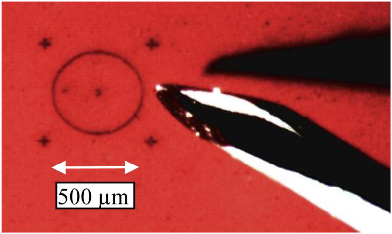
Target and tool tip (hypodermic needle). The target is laser-engraved rubber; oblique lighting creates a tool shadow depth cue.
Hold still: hold the tip stationary above the lower-right cross for 30 seconds.
Circle trace: trace continuously for 60 s around a 500 μm diameter circle.
Move and hold: on a tone cue, move to the next cross (600 μm), then hold there for 15 seconds. Repeat four times. This task resembles common procedures in microsurgery, allowing evaluation of Micron during (relatively) rapid motion. The elapsed time for the move portion was also recorded.
In all tasks the subjects were instructed to try to maintain the tool tip just above the target surface. Lifting the tool during the move portion of the move and hold task was permitted. There were also three test conditions: cancellation using the low-pass and scaling algorithms (§II.F), and off, where cancellation was disabled. This gave nine different task/condition combinations.
We expected that subjects’ performance would vary during the experiment, initially improving due to practice, then dropping due to fatigue. In order to prevent this nuisance variable of task ordering from biasing the results, the order of test conditions and tasks was systematically varied in a nested Latin square design. Each experiment had three groups of nine tasks, separated by two four-minute rest periods. This gave 27 tasks per experiment (approximately 45 minutes).
There is a clear performance difference between the test conditions, so it was impossible for testing to be blind. In order to aid learning of the different operation modes, we told the subject before each task whether they would use “Algorithm A” (scaling), “Algorithm B” (low-pass) or that cancellation was off. To address the possibility that motivated subjects might bias the results, we analyzed how handgrip motion changed under the different conditions.
Data from the trials were logged at 200 Hz for analysis. In order to separate the perceptual depth error from the horizontal position error, the analysis rotated the data so that the Z axis was parallel to the microscope view. Because experiments with an earlier prototype of Micron exhibited a learning curve [38], each subject did the experiment 6 times to allow time for convergence. Data from sessions 4 through 6 were pooled and ANOVA was used to determine the statistical significance of the results. These experiments were conducted with an earlier version of the Micron controller described in §II.K, which implemented a response intermediate between the critically damped and underdamped responses in Table III and §II.N.
B. Results
Fig. 28 gives an overview of the experimental results in the form of learning curves. The curves were similar across tasks and error metrics, so we have shown the mean across tasks of the 3D max error. Performance has largely converged by the fourth experiment, and the final ranking of scaling < low-pass < off is already established by the second session. The learning curve for the surgeons is much flatter, especially in the off condition, suggesting that their existing skills did transfer to this experiment. The low-pass algorithm requires little training, already showing benefit on the first day, while the scaling performance improves with experience.
Fig. 28.

Learning curves for 3D max error (mean across all tasks), broken down by experience level. The flatter curve for surgeons suggests their experience did generalize to the experimental tasks.
Fig. 29 shows the effect on the 3D max error of the experimental variable algorithm. The Tukey-Kramer procedure with error criterion p < 0.05 was used to generate 95% confidence bounds. In comparison to the control condition (off), the effect of the two cancellation algorithms is both significant and substantial, with scaling superior to the low-pass algorithm.
Fig. 29.

Main effect of algorithm on 3D max error. The error bars are 95% confidence intervals. Cancellation significantly reduced error in comparison to the control condition (off).
The task and the subject experience level also had significant effects on error, however these results are unsurprising, and do not reveal anything about the performance of Micron. The reason for introducing multiple tasks was to evaluate whether cancellation was more effective for some tasks than others. The high probability of no effect that ANOVA found for the interaction between task and algorithm (p = 0.54) means that the relative benefit of the algorithms was similar across all three tasks. Likewise, the high probability of no effect on the interaction between experience and algorithm (p = 0.66) indicates that the benefit of cancellation was similar for novices and surgeons. A nested analysis of individual subjects within the groups revealed only one significant interaction: subject(experience) by task (p = 0.001). That is, some subjects did significantly better on some tasks (independent of algorithm), but there was no detectable variation by subject of the improvement due to cancellation. Except where marked with ‘*’, all of the reported measures of both algorithms were found to be significantly different from the off condition and from each other.
Table V shows the effect of cancellation broken down by experience level. Both surgeons and novices benefited significantly from scaling, but only surgeons showed a significant improvement for low-pass.
Table V.
Comparison of 3D Maximum Error by Group (μm)
| Off | Low-pass | Scaling | |
|---|---|---|---|
| Novice | 264 | 214 | 135 |
| 100% | *81% | 51% | |
|
| |||
| Surgeon | 318 | 245 | 178 |
| 100% | 77% | 56% | |
Table VI shows the relative performance of the algorithms under several error metrics. While RMS error is familiar to engineers, in surgical applications maximum error is likely to be more important. Note that cancellation has a greater relative effect on the maximum error than on the RMS error.
Table VI.
Effect of Cancellation by Error Metric
| Off | Low-pass | Scaling | |
|---|---|---|---|
| 3D max | 291 | 229 | 157 |
| 100% | 79% | 54% | |
|
| |||
| 2D max | 219 | 164 | 105 |
| 100% | 75% | 48% | |
|
| |||
| 3D/2D max | 1.34 | 1.43 | 1.58 |
| 100% | *107% | 118% | |
|
| |||
| 3D RMS | 85 | 77 | 58 |
| 100% | 90% | 68% | |
1) Depth Perception Error
Although we do not expect the 2D error (excluding depth error) to be a superior predictor of surgical outcomes, the 2D error reveals how depth perception affects task performance. The 3D error is necessarily greater than the 2D error, but the expected increase due to the added degree of freedom is . The larger measured ratios of 3D/2D error show that vertical (depth) error is larger than horizontal error. Fig. 30 directly shows the increased magnitude of depth error compared to horizontal error in the hold-still task. This distribution is aligned within 5° of the microscope sight-line.
Fig. 30.

Effect of cancellation on point clouds of low-frequency position error during hold-still task. With or without cancellation, error is larger in the visual depth direction, but cancellation is more effective at reducing the horizontal error than the depth error because the positioning accuracy ultimately depends on eye-hand feedback. The user does not perceive this depth error, so the accuracy of the human-in-the-loop system becomes limited by perception, not tremor.
Although the stereo surgical microscope permits binocular depth perception, this is a weak cue. To a considerable extent microsurgeons rely on other cues such as tool shadow and tissue deformation [55]. Therefore these experiments used an oblique light source that gives a strong shadow cue and used a deformable rubber target. Because depth error results from a perceptual limitation, it is not improved by cancellation, so its predominance increases when cancellation is on (Fig. 30(b)).
2) Other Effects of Cancellation
A frequently expressed concern about the Micron concept is that the tool motion due to active cancellation might cause injury at the sclerotomy (the surgical opening where the tool passes inside the eye). We examined the mean across all trials of the 3D maximum motion during the hold still task at both the tip and the sclerotomy location, and found that while motion is reduced by 44% at the tip, it is also reduced by 30% at the sclerotomy. Thus Micron is less likely, not more likely, to damage the sclera than a traditional instrument. This finding that motion at the sclera is reduced by cancellation is inevitable. Kinematically the tip is fixed during cancellation, while the handle is free to move. This constraint that the tip remains fixed also constrains the motion of other points on the tool shaft (to a lesser degree).
Table VII shows that the move time for the move and hold task increased with cancellation. It may be that subjects learned that to get the best results with canceling, they had to move more slowly. Scaling also makes it more natural to move slowly because it scales down speed.
Table VII.
Other Effects of Cancellation
| Off | Low-pass | Scaling | |
|---|---|---|---|
| Move T ime (s) | 2.9 | 3.5 | 4.0 |
| 100% | 118% | 137% | |
|
| |||
| Hand Motion (μm) | 87.1 | 90.5 | 117.6 |
| 100% | *104% | 135% | |
As mentioned in §III.A, the experimental design is not blind, so results are vulnerable to subject bias. To rule out this possibility, we analyzed the hand motion when cancellation was on and compared it to the motion when off. This was done by scoring the accuracy as described above, but using the null tip position (xw) instead of the actual tip position. Table VII shows that hand motion increased with cancellation; however, this can be explained without supposing subjects were biased against the cancellation condition. Because Micron attenuates all hand motion, it reduces the gain of the visuomotor feedback loop (Fig. 4), impairing the ability of eye-hand feedback to stabilize the hand position. Tremor is reduced at the tip, but not by as much as one might expect given the measured attenuation from handle to tip. The increase in handle motion was not significant for in the low-pass condition, but was significant in the scaling condition.
3) Qualitative Results
Fig. 32 shows the effect of Micron with the low-pass algorithm on magnitude of the 3D position error during a hold still task. Although the high-frequency (≈10 Hz) shaking is nearly eliminated, the larger low-frequency motion passes through unattenuated, so the effect of cancellation is modest. Even so, the filter introduces a fraction of a second of lag, which destabilizes the eye-hand feedback loop, limiting the effectiveness of a low-pass filter alone. Fig. 31 shows another hold still task where the scaling algorithm was used. In this case the tremor is larger, in part due to the effect discussed above, yet the resulting tip motion is significantly smaller because motion below 1.5 Hz is attenuated. In both Fig. 32 and Fig. 31 the tip position tracks the goal quite well, rejecting the tremor disturbance and canceling open loop errors. So performance is limited primarily by the ability of the goal filter to attenuate tremor, and not by the active position stabilization feedback loop (§II.N; cf. Table IV and Table VI).
Fig. 32.

Effect of low-pass cancellation algorithm on tremor. Although the tip tracks the goal position quite well, the 1.5 Hz low-pass filter allows most of the tremor to pass through into the goal position.
Fig. 33 shows the effect of the different algorithms on tip motion during the circle tracing task. Accuracy is greatly improved under the scaling condition, though the invisible depth error may be significant (see above).
Fig. 33.

Effect of cancellation on 2D tip motion. These are typical results from three different circle tracing tasks (approximately 15 seconds each circle).
IV. Discussion
These results show the feasibility of the concept of an actively stabilized hand-held tool for tremor suppression —such a system can give a statistically significant reduction in position error for both trained surgeons and non-surgeons. The motion scaling cancellation algorithm gave the largest improvement, a 46% reduction in 3D maximum error, while the improvement with low-pass cancellation was also significant at 21%. The performance improvement was similar across all three tasks tested and all six subjects.
Error in depth perception is an issue in any micromanipulation with handheld tools using a microscope, and it limits the benefits of Micron in the experiments presented here. In the future, the precision measurement intrinsic in Micron could be used as part of a surgical navigation system to help the operator accurately control the depth of the tool tip.
The present tracking system has high accuracy, high bandwidth, and measures both tip and handle motion with the same sensor. Other position sensors could be used, offering their own advantages, such as relaxing the line-of-sight constraints on tool motion and workspace layout.
Increased manipulator range of motion and reduced size would both be beneficial. A manipulator design under development uses piezoelectric linear motors to improve the range of motion and size (with reduced force and slew rate.)
This study has described Micron’s principles of operation and has experimentally demonstrated significant manipulation accuracy improvements. The use of synthetic tasks has enabled precise quantification by eliminating anatomic variability, but distances the results from the ultimate medical application. Improved accuracy may not always give improved clinical outcomes [56], but medical instruments and techniques co-evolve, creating more effective interventions. We have encouraging preliminary results on the use of Micron on biological tissues [57] and the use of procedure-specific goal position computation [58]. Duplicates of the system described here are now being evaluated in two other laboratories, and future work with Micron will involve realistic surgical tasks.
Acknowledgments
This work was supported in part by the National Institutes of Health (grant nos. R21 EY016359, R01 EB000526, and R01 EB007969), the National Science Foundation (Graduate Research Fellowship), and the ARCS Foundation.
Biographies
Robert A. MacLachlan (M‘01) received a B.S. degree in applied mathematics from Carnegie Mellon University in 1987.
He has been a research software developer and engineer at Carnegie-Mellon University since 1983, and has been involved in electronic design since 1993. In 1999 he joined the Robotics Institute at Carnegie Mellon, where he has designed and developed sensor and control hardware and software for mobile robots, and currently develops intelligent medical instruments at the Surgical Mechatronics Laboratory. His research interests include medical robotics, sensor design, signal processing and control systems, with particular emphasis on exploiting the combination of sensitive measurements and effective data interpretation algorithms in order to enable the construction of novel mechatronic systems that solve real-world problems.
Brian C. Becker (M‘05) received a B.S. degree in computer engineering from the University of Central Florida in 2007 and an M.S. degree in robotics from Carnegie Mellon University in 2010.
Since 2007, he has been a Ph.D. student researching medical robotics in the Robotics Institute at Carnegie Mellon. He currently specializes in computer vision, control systems, and microsurgical instruments.
Jaime Cuevas Tabarés received a B.S. degree in electrical engineering from the University of León, Spain, in 2007 and a M.S. degree in electrical engineering from the University of Valladolid, Spain, in 2010.
Since 2011 he has been working as a Research Engineer at SEADM, Spain, on electronic design for high sensitivity vapor analysis instruments.
Gregg Podnar (M‘08) was awarded a B.S. degree, self-defined, in 1976 by Carnegie-Mellon University, and has done graduate work in computer science at CMU.
He is currently a Program Manager at the Robotics Institute of Carnegie Mellon University. Over three decades of wide-ranging research, he has developed many task-specific mobile robots and manipulators; stereoscopic telepresence systems; and surgical instruments. He holds U.S. and international patents; has authored or coauthored over three dozen papers on robotics, planetary mineral prospecting, ocean and surface water quality, aircraft skin inspection, predictive energy management for electric commuter vehicles, stereoscopic imaging, and engineering design; and is a principal in a company that builds computer-based vision examination equipment.
Mr. Podnar’s other appointments have included: Visiting Fellow, Minerals Down Under Flagship, CSIRO, Australia; Visiting Professor of Computer Science, JiangXi University, China; Research Associate in the Engineering Design Research Center at CMU; and Research Fellow in the Studio for Creative Inquiry, College of Fine Arts, CMU.
Louis A. Lobes, Jr. M.D. received an M.D. from Cornell University Medical College in 1970. He has been Clinical Associate Professor of Ophthalmology at the University of Pittsburgh School of Medicine since 1984, with clinical concentration on Vitreoretinal surgery, Macular Degeneration and Diabetic Retinopathy. He has been coinvestigator in the Endophthalmitis Vitrectomy Study, Age Related Eye Disease Study, Submacular Surgical Trial and Comparison of AMD Treatments Trial, NIH funded studies. His main research presently is with the Micron robotics project.
Dr. Lobes is a member of the Retina Society, Macular Society, & American Academy of Ophthalmology.
Cameron N. Riviere (S‘94–M‘96–SM‘10) received B.S. degrees in aerospace engineering and ocean engineering from the Virginia Polytechnic Institute and State University, Blacksburg, in 1989, and the Ph.D. degree in mechanical engineering from The Johns Hopkins University, Baltimore, MD, in 1995.
Since 1995, he has been with the Robotics Institute at Carnegie Mellon University, Pittsburgh, PA, where he is presently Associate Research Professor and the Director of the Surgical Mechatronics Laboratory. His research interests include medical robotics, control systems, signal processing, learning algorithms, and human–machine interfaces for biomedical applications, including surgery and rehabilitation.
Prof. Riviere is an Associate Editor on the Conference Editorial Boards of the IEEE Robotics and Automation Society and the Engineering in Medicine and Biology Society, and was one of the guest editors of the special issue on medical robotics in the journal Proceedings of the IEEE in 2006.
Contributor Information
Robert A. MacLachlan, Robotics Institute, Carnegie Mellon University, Pittsburgh, PA 15213 USA.
Brian C. Becker, Robotics Institute, Carnegie Mellon University, Pittsburgh, PA 15213 USA.
Jaime Cuevas Tabarés, University of Valladolid, Spain.
Gregg W. Podnar, Robotics Institute, Carnegie Mellon University, Pittsburgh, PA 15213 USA
Louis A. Lobes, Jr., Dept. of Ophthalmology, University of Pittsburgh Medical Center, Pittsburgh, PA 15213 USA
Cameron N. Riviere, Email: camr@ri.cmu.edu, Robotics Institute, Carnegie Mellon University, Pittsburgh, PA 15213 USA.
References
- 1.Sandoval Garcia R, et al. Positioning accuracy of neurosurgeons. Proc 29th Annu Int Conf IEEE Eng Med Biol Soc. 2007:206–209. doi: 10.1109/IEMBS.2007.4352259. [DOI] [PubMed] [Google Scholar]
- 2.Safwat B, et al. The Role of Posture, Magnification, and Grip Force on Microscopic Accuracy. Ann Biomed Eng. 2009;37:997–1006. doi: 10.1007/s10439-009-9664-7. [DOI] [PubMed] [Google Scholar]
- 3.Brooks HL., Jr Macular hole surgery with and without internal limiting membrane peeling. Ophthalmology. 2000;107:1939–48. doi: 10.1016/s0161-6420(00)00331-6. discussion 1948–9. [DOI] [PubMed] [Google Scholar]
- 4.Opremcak EM, Bruce RA. Surgical decompression of branch retinal vein occlusion via arteriovenous crossing sheathotomy. Retina. 1999;19:1–5. doi: 10.1097/00006982-199901000-00001. [DOI] [PubMed] [Google Scholar]
- 5.Tang WM, Han DP. A study of surgical approaches to retinal vascular occlusions. Arch Ophthalmol. 2000;118:138–143. doi: 10.1001/archopht.118.1.138. [DOI] [PubMed] [Google Scholar]
- 6.Mürbe D, et al. Tremor in Otosurgery: Influence of Physical Strain on Hand Steadiness. Otology & Neurotology. 2001;22:672–677. doi: 10.1097/00129492-200109000-00019. [DOI] [PubMed] [Google Scholar]
- 7.Ransick A, Davidson EH. A Complete Second Gut Induced by Transplanted Micromeres in the Sea Urchin Embryo. Science. 1993;259:1134. doi: 10.1126/science.8438164. [DOI] [PubMed] [Google Scholar]
- 8.Voyles RM, Hulst S. Micro/macro force-servoed gripper for precision photonics assembly and analysis. Robotica. 2005;23:401–408. [Google Scholar]
- 9.Elble RJ, Koller WC. Tremor. Baltimore: Johns Hopkins; 1990. [Google Scholar]
- 10.Vasilakos K, et al. Interaction of tremor and magnification in a motor performance task with visual feedback. J Mot Behav. 1998;30:158–168. doi: 10.1080/00222899809601333. [DOI] [PubMed] [Google Scholar]
- 11.Timmer J, et al. Quantitative analysis of tremor time series. Electroencephalogr Clin Neurophysiol. 1996;101:461–468. [PubMed] [Google Scholar]
- 12.Stiles RN. Mechanical and neural feedback factors in postural hand tremor of normal subjects. J Neurophysiol. 1980;44:40–59. doi: 10.1152/jn.1980.44.1.40. [DOI] [PubMed] [Google Scholar]
- 13.Raethjen J, et al. Determinants of physiologic tremor in a large normal population. Clin Neurophysiol. 2000;111:1825–1837. doi: 10.1016/s1388-2457(00)00384-9. [DOI] [PubMed] [Google Scholar]
- 14.Endo H, Kawahara K. Relationship between hand stability and the 10-Hz physiological tremor during various manual tasks. Ergonomics. 2010;53:491–501. doi: 10.1080/00140130903556336. [DOI] [PubMed] [Google Scholar]
- 15.McRuer DT, Jex HR. A review of quasi-linear pilot models. IEEE Trans Hum Factors Electron. 1967;HFE-8:231–249. [Google Scholar]
- 16.Jagacinski RJ, Flach J. Control Theory for Humans: Quantitative Approaches to Modeling Performance. Mahwah, N.J.: L. Erlbaum Associates; 2003. [Google Scholar]
- 17.Loram ID, et al. The frequency of human, manual adjustments in balancing an inverted pendulum is constrained by intrinsic physiological factors. J Physiol (Lond) 2006;577:417–432. doi: 10.1113/jphysiol.2006.118786. [DOI] [PMC free article] [PubMed] [Google Scholar]
- 18.Kuchen B, et al. Frequency response of the human controller for various processes and stochastic testsignals. Biol Cybern. 1977;27:33–39. doi: 10.1007/BF00357708. [DOI] [PubMed] [Google Scholar]
- 19.Dogangil G, et al. A review of medical robotics for minimally invasive soft tissue surgery. Proc Inst Mech Eng [H] 2009;223:1–27. doi: 10.1243/09544119JEIM591. [DOI] [PubMed] [Google Scholar]
- 20.Ballantyne G, Moll F. The da Vinci telerobotic surgical system: the virtual operative field and telepresence surgery. Surg Clin North Am. 2003;83:1293–1304. doi: 10.1016/S0039-6109(03)00164-6. [DOI] [PubMed] [Google Scholar]
- 21.Bourla DH, et al. Feasibility study of intraocular robotic surgery with the da Vinci surgical system. Retina. 2008;28:154–158. doi: 10.1097/IAE.0b013e318068de46. [DOI] [PubMed] [Google Scholar]
- 22.Mulgaonkar AP, et al. A prototype surgical manipulator for robotic intraocular micro surgery. Stud Health Technol Inform. 2009;142:215–217. [PubMed] [Google Scholar]
- 23.Jensen PS, et al. Toward robot-assisted vascular microsurgery in the retina. Graefes Arch Clin Exp Ophthalmol. 1997;235:696–701. doi: 10.1007/BF01880668. [DOI] [PubMed] [Google Scholar]
- 24.Hunter IW, et al. A teleoperated microsurgical robot and associated virtual environment for eye surgery. Presence. 1993;2:265–280. [Google Scholar]
- 25.Ueta T, et al. Robot-assisted vitreoretinal surgery: development of a prototype and feasibility studies in an animal model. Ophthalmology. 2009;116:1538–1543. doi: 10.1016/j.ophtha.2009.03.001. [DOI] [PubMed] [Google Scholar]
- 26.Das H, et al. Evaluation of a telerobotic system to assist surgeons in microsurgery. Comput Aided Surg. 1999;4:15–25. doi: 10.1002/(SICI)1097-0150(1999)4:1<15::AID-IGS2>3.0.CO;2-0. [DOI] [PubMed] [Google Scholar]
- 27.Taylor R, et al. A steady-hand robotic system for microsurgical augmentation. International Journal of Robotics Research. 1999;18:1201–1210. [Google Scholar]
- 28.Mitchell B, et al. Development and application of a new steady-hand manipulator for retinal surgery. Proc IEEE Int Conf Robot Autom. 2007:623–629. [Google Scholar]
- 29.Gupta P, et al. Surgical forces and tactile perception during retinal microsurgery. Lect Notes Comput Sci. 1999;1679:1218–1225. [Google Scholar]
- 30.Salcudean SE, et al. Performance measurement in scaled teleoperation for microsurgery. Lect Notes Comput Sci. 1997;1205:789–798. [Google Scholar]
- 31.Okamura AM. Haptic feedback in robot-assisted minimally invasive surgery. Curr Opin Urol. 2009;19:102–107. doi: 10.1097/MOU.0b013e32831a478c. [DOI] [PMC free article] [PubMed] [Google Scholar]
- 32.Tavakoli M, et al. Haptic interaction in robot-assisted endoscopic surgery: a sensorized end-effector. International Journal of Medical Robotics and Computer Assisted Surgery. 2005;01:53. doi: 10.1002/rcs.16. [DOI] [PubMed] [Google Scholar]
- 33.Iordachita I, et al. A sub-millimetric, 0.25 mN resolution fully integrated fiber-optic force-sensing tool for retinal microsurgery. Int J Comput Assist Radiol Surg. 2009;4:383–390. doi: 10.1007/s11548-009-0301-6. [DOI] [PMC free article] [PubMed] [Google Scholar]
- 34.Kuchenbecker KJ, Niemeyer G. Induced master motion in force-reflecting teleoperation. Journal of Dynamic Systems, Measurement, and Control. 2006;128:800–810. [Google Scholar]
- 35.Berkelman PJ, et al. A miniature microsurgical instrument tip force sensor for enhanced force feedback during robot-assisted manipulation. IEEE Trans Robot Autom. 2003;19:917–921. [Google Scholar]
- 36.Ang WT. PhD doctoral. Robotics Institute, Carnegie Mellon University; Pittsburgh, Pa: 2004. Active tremor compensation in handheld instrument for microsurgery. [Google Scholar]
- 37.Choi DY, Riviere CN. Flexure-based Manipulator for Active Handheld Microsurgical Instrument. Proc 27th Annu. Int. Conf. IEEE Eng. Med. Biol. Soc; 2005. pp. 2325–2328. [DOI] [PubMed] [Google Scholar]
- 38.Choi DY, et al. Test of tracing performance with an active handheld micromanipulator. Proc. 29th Annu. Int. Conf. IEEE Eng. Med. Biol. Soc; 2007. pp. 3638–3641. [DOI] [PubMed] [Google Scholar]
- 39.Latt WT, et al. Compact sensing design of a hand-held active tremor compensation instrument. IEEE Sens J. 2009;9:1864–1871. doi: 10.1109/JSEN.2009.2030980. [DOI] [PMC free article] [PubMed] [Google Scholar]
- 40.Riviere CN, Thakor NV. Modeling and canceling tremor in human-machine interfaces. IEEE Eng Med Biol Mag. 1996;15:29–36. [Google Scholar]
- 41.Riviere CN, et al. Toward active tremor canceling in handheld microsurgical instruments. IEEE Trans Robot Autom. 2003;19:793–800. [Google Scholar]
- 42.Lee KM, Shah DK. Kinematic analysis of a three-degrees-of-freedom in-parallel actuated manipulator. IEEE J Robot Autom. 1988;4:354–360. [Google Scholar]
- 43.MacLachlan RA, Riviere CN. High-speed microscale optical tracking using digital frequency-domain multiplexing. IEEE Trans Instrum Meas. 2009;58:1991–2001. doi: 10.1109/TIM.2008.2006132. [DOI] [PMC free article] [PubMed] [Google Scholar]
- 44.Horn BKP. Closed-form solution of absolute orientation using unit quaternions. J Opt Soc Am A. 1987;4:629–642. [Google Scholar]
- 45.Greer AD, et al. Human-machine interface for robotic surgery and stereotaxy. IEEE/ASME Trans Mechatronics. 2008;13:355–361. [Google Scholar]
- 46.Elliott SJ, Sutton TJ. Performance of feedforward and feedback systems for active control. IEEE Trans Speech Audio Process. 1996;4:214–223. [Google Scholar]
- 47.Garcia CE, Morari M. Internal model control. A unifying review and some new results. Industrial & Engineering Chemistry Process Design and Development. 1982;21:308–323. [Google Scholar]
- 48.Brosilow C, Joseph B. Techniques of Model-Based Control. Upper Saddle River, N.J.: Prentice Hall; 2002. [Google Scholar]
- 49.Lee JH, et al. State-space interpretation of model predictive control. Automatica. 1994;30:707–717. [Google Scholar]
- 50.Zheng A, et al. Anti-windup design for internal model control. International Journal of Control. 1994;60:1015–1024. [Google Scholar]
- 51.Abe N, Yamanaka K. Smith predictor control and internal model control - a tutorial. SICE 2003 Annual Conference; 2003. pp. 1383–1387. [Google Scholar]
- 52.Ang WT, et al. Feedforward controller with inverse rate-dependent model for piezoelectric actuators in trajectory-tracking applications. IEEE/ASME Trans Mechatronics. 2007;12:134–142. [Google Scholar]
- 53.Newcomb CV, Flinn I. Improving the linearity of piezoelectric ceramic actuators. Electron Lett. 1982;18:442–444. [Google Scholar]
- 54.Kageshima M, et al. Wideband and hysteresis-free regulation of piezoelectric actuator based on induced current for high-speed scanning probe microscopy. Rev Sci Instrum. 2006;77:103701. [Google Scholar]
- 55.Chen JYC, et al. Human performance issues and user interface design for teleoperated robots. IEEE Trans Syst, Man, Cybern C, Appl Rev. 2007;37:1231–1245. [Google Scholar]
- 56.DiMaio S, et al. Challenges in image-guided therapy system design. Neuroimage. 2007;37:S144–S151. doi: 10.1016/j.neuroimage.2007.04.026. [DOI] [PMC free article] [PubMed] [Google Scholar]
- 57.Tabarés JC, et al. Cell micromanipulation with an active handheld micromanipulator. Proc. 32nd Annu. Int. Conf. IEEE Eng. Med. Biol. Soc; 2010. pp. 4363–4366. [DOI] [PMC free article] [PubMed] [Google Scholar]
- 58.Becker BC, et al. Semiautomated intraocular laser surgery using handheld instruments. Lasers Surg Med. 2010;42:264–273. doi: 10.1002/lsm.20897. [DOI] [PMC free article] [PubMed] [Google Scholar]