Abstract
Needle insertion is a critical aspect of many medical treatments, diagnostic methods, and scientific studies, and is considered to be one of the simplest and most minimally invasive medical procedures. Robot-assisted needle steering has the potential to improve the effectiveness of existing medical procedures and enable new ones by allowing increased accuracy through more dexterous control of the needle tip path and acquisition of targets not accessible by straight-line trajectories. In this article, we describe a robot-assisted needle steering system that uses three integrated controllers: a motion planner concerned with guiding the needle around obstacles to a target in a desired plane, a planar controller that maintains the needle in the desired plane, and a torsion compensator that controls the needle tip orientation about the axis of the needle shaft. Experimental results from steering an asymmetric-tip needle in artificial tissue demonstrate the effectiveness of the system and its sensitivity to various environmental and control parameters. In addition, we show an example of needle steering in ex vivo biological tissue to accomplish a clinically relevant task, and highlight challenges of practical needle steering implementation.
I. Introduction
Needles are widely used in medicine to deliver treatments and acquire tissue samples for diagnosis due to their ability to reach subsurface targets with little trauma to the patient. In many procedures, accurate placement of the needle tip within an organ is vital for a successful outcome. Poor placement of a needle tip can result in problems such as false negatives from a biopsy, imprecise delivery of radiation therapy (such as radioactive seeds implanted during brachytherapy), and ablation of healthy tissue instead of cancerous tissue. Several factors, including errors in insertion location, needle bending, and tissue deformation, can lead to poor needle tip placement. When such errors occur in clinical settings, the solution typically involves retraction and reinsertion – in current practice, a clinician has limited control over the path of a needle once inserted into the tissue. The ability to steer a needle inside tissue could significantly improve the effectiveness of needle-based procedures.
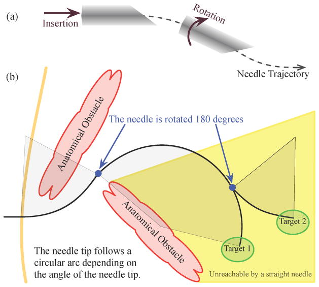
Needle steering can also allow access to subsurface targets unreachable by conventional straight needles, as shown in Figure 1. In some medical procedures, a straight-line path between a feasible insertion site and a desired target is blocked by anatomical structures. For example, the ribs often obstruct percutaneous access to ablate portions of the liver. An alternate path exists through the lung cavity, but this incurs significant risk of collapsing part of the lung. Without a safe percutaneous route, access must be provided by opening the patient’s abdominal cavity; this causes significant trauma, thereby increasing risk of infection and lengthening recovery time. Needle steering can be used to avoid these anatomical obstacles, greatly expanding the volume of human tissue that can be safely reached by percutaneous means. This can, in turn, lead to better patient outcomes because needle entry wounds are small – thus greatly accelerating recovery.
Fig. 1.
(a) The steering mechanism of asymmetric-tip needles [1] is due to forces between the tissue and needle tip that deflect the needle during insertion. Subsequent rotation of the needle shaft (from outside the patient) reorients the tip so that further insertion deflects the tip in a new direction. The combination of these two control inputs, along with a flexible needle shaft, allows the needle to reach targets not accessible by straight paths. (b) A steerable needle can reach subsurface targets not accessible using conventional needles and multiple targets can be reached without fully retracting the needle. Anatomical obstacles could include bones, vessels, nerves, and other structures that a needle might damage or not be able to penetrate.
Because needle insertion involves complex mechanical interactions between the needle and tissue, it is difficult for clinicians to use manual manipulation to steer needles. Modeling, planning, and control of needles using robotics-based algorithms and devices are key to the success of many proposed needle steering applications. Robot-assisted needle steering is exciting not only due to its potential impact on medicine, but also as a source of new research questions in the field of robotics. Steerable needles share features common to other robots and systems, allowing the application of existing techniques to a new domain. Steerable needles also introduce new technical challenges due to tissue deformation, the nature of uncertainty during insertion, and complex mechanical interactions – addressing these challenges is leading to new tools that can be applied to a wide range of robotics problems. This article describes the design, implementation, and experimental evaluation of a system that steers needles based on tip asymmetry. Our experiments evaluate how variations in the independent controllers and path planner affect the overall performance of the system. We also describe avenues for future research by highlighting open research challenges and a method for performing a brachytherapy procedure.
II. Background
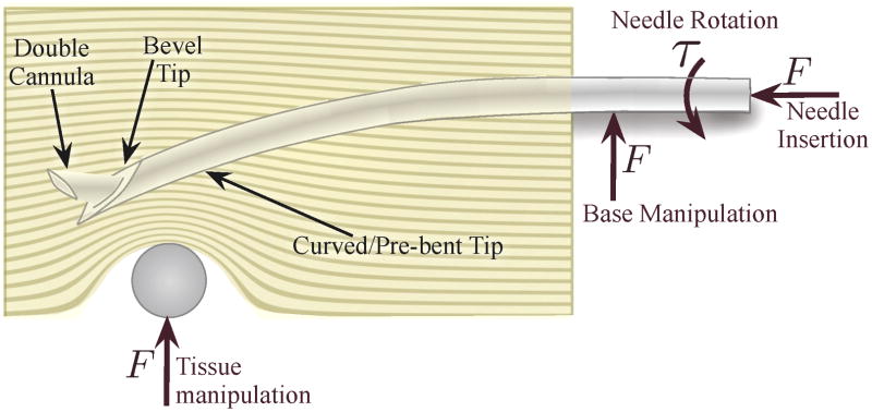
In recent years, several methods of controlling a needle inside tissue have emerged, including tip-based steering, base manipulation, and tissue manipulation. Each method has benefits and drawbacks, primarily related to the relationship between steerability and distance of the needle tip inside the tissue. However, as illustrated in Figure 2, all of these methods may be combined to enable high steerability at multiple insertion depths while minimizing tissue damage.
Fig. 2.
Several different methods of needle steering have been proposed in the literature: Asymmetry-based steering uses the forces generated at the tip during insertion to bend the needle. The tip curvature can be either constant or variable using multiple concentric cannulas. Base manipulation bends the needle by applying a force perpendicular to the insertion direction. Tissue manipulation can move the targets and obstacles into and out of the needle’s path, respectively. Each of these methods are conceptually independent, but may be combined, thereby increasing control authority over the needle trajectory.
A. Tip-Steerable Needles
When a needle with an asymmetric tip is inserted into a firm medium such as tissue, the shape of the tip and its interaction with the medium creates an imbalance in lateral force. If the medium does not deform significantly, the resultant steering force causes the needle tip to follow a circular arc and, if the needle is flexible relative to the medium, the rest of the needle shaft will follow the same path. Webster et al. [1] developed and validated a kinematic nonholonomic model of this type of highly flexible needle steered in artificial tissue by using the asymmetry of a bevel tip. The model can be thought of as the trajectory of a planar bicycle (or Dubin’s car) with “locked” steering angle. Different needle-tissue pairs essentially result in a change in the model’s key parameter, the steering angle, which can be used to control the needle tip position [2].
The direction of motion of the needle tip is controlled by rotating the shaft (spinning it around the needle’s long axis) at the base. Since the needle shaft is held in place by the tissue, this causes the tip of the needle to rotate, although some lag can be introduced between base and tip [3]. In terms of the kinematic bicycle model, the reorientation of the tip amounts to rotating the plane in which the bicycle rides. For needle steering, the rotation is exerted on the base of the needle outside the tissue, so the needle becomes a flexible drive shaft. The steered needle can follow paths in any plane using only the insertion and rotational degrees of freedom. Pre-bent needles [4] have also been used to achieve curved needle paths. Inserting and retracting a second concentric pre-bent needle can control the amount of curvature at the tip [5]. Additionally, the needle can be spun intermittently to modify the apparent radius of curvature resulting from insertion [6]. Both of these methods allow the radii of curvature to change, but the significant challenge is to allow smaller radii of curvature without damaging the tissue. A survey of needle insertion modeling and approaches can be found in [7]. Figure 3 shows an example of a needle steered through artificial tissue and ex vivo liver.
Fig. 3.
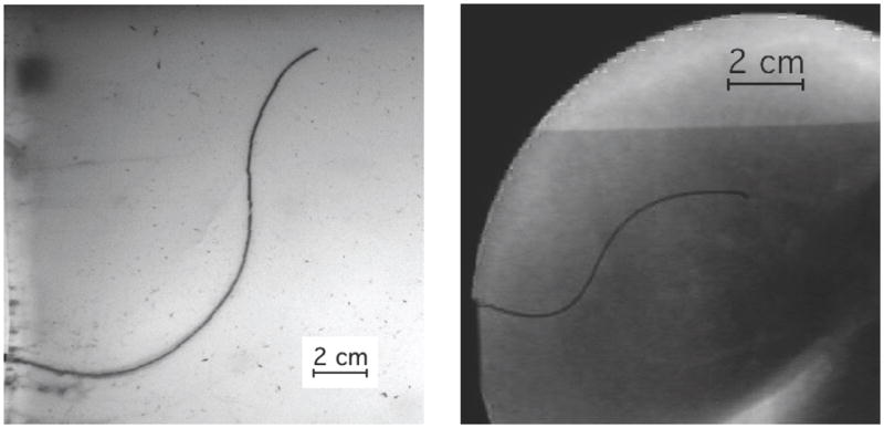
A demonstration of two tip-steered needles guided through artificial tissue (left) and ex vivo liver (right) on paths determined using the Stochastic Motion Roadmap (SMR) planner [2]. The SMR planner finds a two-dimensional path most likely to guide the needle into the target while avoiding the obstacles. The planned motion is implemented by rotating the needle to curve left or right during insertion.
B. Base Manipulation
Manipulating the base of the needle perpendicular to the insertion direction can also steer the needle [8], [9]. These perpendicular motions cause the entire needle shaft to bend inside the tissue, much like a beam resting on a compliant fulcrum. The insertion point acts as the fulcrum, so any motion of the needle base perpendicular to the needle insertion causes the tip to move in roughly the opposite direction.
This method suffers from depth dependence, resulting in decreasing needle steerability as the needle is inserted further into the tissue – more tissue can resist the lateral force and the moment arm also increases. The force at the base must increase to generate the same change in tip path throughout the insertion and a thin needle is likely to slice through the tissue if too much force is exerted. However, base manipulation and tip-steered needles can likely be used together for additional control over the needle throughout the entire insertion since the asymmetric force on a tip-steered needle is roughly independent of depth.
C. Tissue Manipulation
It is also possible to manipulate the tissue so that targets move into the path of the needle and obstacles and sensitive tissues move out of the path of the needle. Physicians already perform such tissue manipulation by hand. Recent work has shown that robotic control can achieve this effect using blunt end-effectors and real-time image feedback in both experiments [10] and more complex simulations [11]. Robotic tissue manipulation systems could be combined with the other needle steering approaches described above, although it may be challenging to develop practical tissue manipulation mechanisms for deep subsurface targets.
III. Components for Needle Control
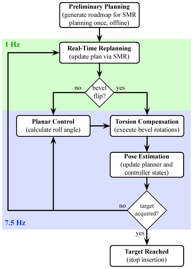
In this section, we describe the design and integration of independent components that form a complete asymmetric-tip needle steering system. The primary components are: a motion planner, a planar controller, and a torsion compensator. Each component was developed separately to control a subset of the entire needle motion and assumes the other components perfectly control other aspects of the motion. The motion planner is only concerned with guiding the needle around obstacles to a target in a desired plane and assumes that the needle tip will stay in that plane. The goal of the planar controller is to maintain the needle in the desired plane. Together, the motion planner and controller are able to specify and control the full 6-degree-of-freedom pose of the needle tip. The torsion compensator helps reduce the lag effect caused by the long transmission from the base to the tip during axial rotations. The system modules operate at different levels and with different timing. Figure 4 provides an overview of how the modules interact.
Fig. 4.
The integrated needle system is composed of several controllers operating at different rates. The pose estimator, planar controller, and torsion compensator are updated at the camera refresh rate of 7.5 Hz. After each image is acquired, the estimator estimates the needle tip orientation and the planar controller commands a base rotation which maintains the needle tip near the desired plane. The planner operates at 1 Hz and decides the optimal bevel direction. The torsion compensator rotates the base to ensure that the needle tip is at the desired angle.
A. Planar Motion Planning
The motion planner computes high-level actions that will have the highest probability of avoiding obstacles while guiding the needle to the target. The planner can execute two high-level actions: rotate bevel-right or rotate bevel-left. The bevel direction is a simplifying abstraction that collapses the continuous roll angle of the needle into a binary action. The planar controller described in the next section corrects for deviations out of the desired plane.
For a given needle-tissue combination and set of anatomical structures, there may be multiple feasible paths the needle could take to reach a target while avoiding obstacles. The shortest path to the target can be found, but this path may require navigating through narrow passages between obstacles where a slight deflection from the intended path could result in a collision with an obstacle. Instead, the planner used in this system accounts for uncertainty in the needle motion and seeks to maximize the probability that the needle path will avoid obstacles and reach the target.
We invoke the Stochastic Motion Roadmap (SMR), a general motion planning framework that explicitly considers uncertainty in robot motion to maximize the probability of success [2]. This method extends prior work on motion planning under uncertainty for steerable needles [12] by enabling more general uncertainty models and robot/needle kinematics. For our problem, the SMR method requires polygonal outlines of the obstacles in the imaging plane, the start pose of the needle, and a target location in the plane. The method then builds a roadmap by sampling obstacle-free states in the configuration space. Using an uncertainty model based on the kinematic model of steerable needles, the method locally samples possible outcomes for each high-level action to estimate state transition probabilities between the states. We use the roadmap to formulate a Markov Decision Process (MDP), which we solve using Infinite Horizon Dynamic Programming to compute a stochastically optimal plan to acquire the target. Once the roadmap has been constructed and the MDP solved, the optimal next action for any current needle configuration can be obtained instantaneously. This capability enables the SMR planner to be used inside a feedback loop in the integrated needle steering system.
The motion planner operates at the highest level, computing the optimal path to reach the target. The motion planner is queried once per second (corresponding to a specific fixed distance since the insertion speed is constant) in the experiments below, but the interval can be modified as necessary. At each query, the state estimator provides the motion planner with the needle tip’s current position and orientation (x, y, φ) and bevel direction (left or right). The planner then returns the optimal next action, which is either bevel-left or bevel-right. The bevel-left or bevel-right command is sent to the torsion compensator or the planar controller, depending on whether the bevel direction changes.
To precisely project a likely path, the SMR planner requires an accurate specification of the kinematics of the needle. In the experiments described in Section IV, we added a pre-bend near the bevel at the tip of the needle to achieve a smaller radius of curvature, and thus enhanced steerability. However, using a pre-bent needle results in discontinuities of the tip position and yaw angle, and potential tissue damage, when the bevel changes direction. We have found in previous work that the needle tip can move by as much as 4 mm and the trajectory can change by up to 22° [13]. The discontinuous motion is perpendicular to the insertion axis, which violates the nonholonomic model of the needle used in the planar controller and prior needle steering motion planners. Ignoring the discontinuous motion could cause the needle to translate into an obstacle.
To account for the discontinuities in the needle position and angle, we extended the kinematic model used in the previous motion planner [2] to predict the new position after a bevel rotation. The extended kinematic model requires three parameters: the needle radius of curvature, a displacement offset for when the bevel/pre-bend direction is changed, and an orientation angle offset for when the bevel/pre-bend direction is changed. We experimentally determined these three values.
B. Planar Image-Based Control
Any small deviation in needle angle from vertical will cause the needle to diverge from the desired two-dimensional (2D) plane. However, Kallem and Cowan [14] showed that a tip-steerable needle can be controlled to stay in a desired plane by only considering three of the six degrees of freedom: distance away from the desired plane, pitch away form the plane, and roll of the needle. This “task-induced” reduction enabled the design of the observer and controller for a lower-dimensional, simpler system. In our needle steering system, the planar control law guides the needle to stay in the desired 2D plane. The feedback controller requires only a measurement of the distance of the needle tip from the desired plane, from which it constructs a state estimate of the three states of interest (roll, pitch, and distance). The other three states (yaw, and the two remaining translational degrees of freedom) can also be recovered using a linear observer obtained through state immersion.
The planar controller and state estimator operate at a low level. The control and estimate is calculated for each pair of images from the cameras, which are received at 7.5 Hz. Real-time tracking of the needle provides the (x, y, z) positions of the needle tip. We calibrate the stereo cameras using the Camera Calibration Toolbox1 for MATLAB and assign a world reference frame. We compensate for the refraction of the gel by computing the refractive index of the gel and use it in the triangulation process. Since the tip is triangulated from two cameras with limited resolution and noise, the height (z) measurements are noisy. The model-based observer estimates the roll, pitch, and distance of the needle tip to the desired plane over time. Of course, an encoder can read the roll angle at the base of the needle, but that is not necessarily the same as the angle at the tip even with perfect alignment of the actuator and the tip before insertion [3]. After triangulating the camera images, the controller adjusts the angle of the needle base to guide the needle to the desired plane. The controller is unconcerned with the position and yaw (x, y, φ) within the desired 2D plane; that is the job of the high-level motion planner. Likewise, the motion planner is unconcerned with the height, roll, and pitch since it assumes the planar controller maintains them correctly.
At the start of each insertion, the user is asked to click near the tip of the needle to provide a local region in which a corner detector locates the needle tip. The needle is then tracked during the insertion using the Brute Force tracker in the CISST software libraries2. Throughout the motion, the system monitors the triangulated position. If the deviation is too large or the needle is too far away from the plane, the system will pause the insertion and ask the user to reselect the location of the needle. A stop button will similarly pause the insertion to allow the operator to verify the needle location or abort the procedure by retracting the needle. This is a safety feature to ensure that the needle tracking is not lost.
For the experiments described in Section IV, we used stereo cameras, but clinical procedures (similar to the brachytherapy procedure in Section V-B) will use bi-plane fluoroscopy or three-dimensional (3D) ultrasound to directly measure the needle tip position inside the tissue. Since the needle is too thin for direct measurement of the tip orientation, we use the observer’s estimate of orientation. The planar controller requires two cameras for triangulation of the needle height, thus a single camera frame is insufficient to adequately maintain the planar motion. When using a single C-arm fluoroscope, we anticipate that an estimate of the 3D position can be obtained based on information from two asynchronous camera sources, such as two positions of the C-arm. Clinical systems could potentially use an estimation scheme based on alternating camera positions to estimate the 3D needle position.
C. Torsion Compensation During 180° Bevel Flips
The motion planner and planar controller described above are based on the kinematic model of needle steering [1], which does not account for the “lag” between the base angle and tip angle resulting from torsional friction at the needle-tissue interface and the torsional compliance of the needle. This effect is substantial during the 180° rotations (bevel flips) commanded by the motion planner. The lag has been shown to be as high as 45° for a needle inserted 10 cm into an artificial tissue similar to the one used in our experiments [3]. Even a small discrepancy is likely to result in poor performance or failure of the motion planner and image-guided controller.
For the experiments performed here, we used a torsion compensator that estimates and controls the needle tip using a mechanics-based model of the rotational dynamics of the needle interacting with the tissue during insertion [3]. The dynamics are formulated with friction using a fourth-order continuous forced modal model. The resulting control action of the compensator axially rotates the needle at its base so that the tip angle is at the desired location. Without torsion compensation, the lagged rotation of the needle tip would result in the needle deviating significantly out of the desired plane of motion.
The torsion compensator is updated at 7.5 Hz, but operates at 200 Hz to continuously maintain the tip at the desired angle and, thus, help maintain the needle in the desired plane. The 180° bevel flips commanded by the motion planner and the small adjustments commanded from the planar controller are implemented using the torsion compensator.
IV. Experimental Evaluation
Our needle steering system is composed of the components described in Section III, each of which has been individually tuned to achieve good performance in previous work. However, experimental evaluation of a complete system that integrates planning, real-time control, and torsion compensation has never previously been reported in the archival literature. An initial demonstration of our integrated system with discrete motion intervals was presented at the IEEE/RAS-EMBS International Conference on Biomedical Robotics and Biomechatronics in 2008 [13]. Here, we describe experiments of continuous insertion designed to determine the influence of each component’s contribution in driving the needle to the desired target.
Several assumptions were made during the implementation of the individual system components. Our goal in the following experiments was to understand the extent to which these assumptions are valid and what trade-offs the assumptions introduce. In particular, we will explore system performance when specific assumptions made for each component are violated (e.g., staying in a plane).
The experiments presented here are using artificial tissue to allow consistency from trial to trial; natural tissue has structures such as muscle fibers and blood vessels that can alter the needle motion, making it difficult to ascertain the extent to which our underlying systems-level assumptions limit performance. There is still some variability in the needle path, but recent closed form models validated with experiments are able to model over 95% of the variance in the needle’s path distribution as it is inserted into the tissue [15]. In these experiments, we minimize the number of variable parameters so we can distinguish characteristic system behaviors from issues associated with tissue properties and medical imaging limitations. Our relatively homogeneous and isotropic artificial tissue allows data from different insertions to be compared, enabling us to evaluate system-level performance. Further, the artificial tissue is transparent, so conventional video cameras can be used to acquire images of the needle. Future work will investigate the effects of natural tissue on needle steering in a more systematic way; a preliminary demonstration is presented in Section V.
A. Methods
We manufactured transparent plastisol artificial tissue (M-F Manufacturing Co., Inc., Fort Worth, TX) using plastic and softener in a ratio of 4:1. The artificial tissue used in these experiments is the same as that used in [16] and [3], which were shown to have a Young’s modulus and rotational friction similar to a prostate [17], which is one the target organs. We used two “needles” made of solid Nitinol wire (Nitinol Devices and Components, Fremont, CA, USA). Nitinol was used for its superelastic properties; the needles can curve in tissue with a fairly small radius of curvature without plastically deforming. However, before the experiments were performed, we plastically deformed each needle to create a sharp prebend. The small needle was 0.37 mm in diameter, with a 45° bevel angle and a 12° bend in a complementary direction 4 mm from the tip. The large needle was 0.58 mm in diameter, with a 40° bevel angle and a 37° bend in a complementary direction 12 mm from the tip. These values were selected so the two needles would have a similar radii of curvature. In the given artificial tissue, the radii of curvature of the small and large needles were experimentally determined to be 6.0 cm and 5.5 cm, respectively. The large needle can achieve a smaller radius of curvature than the small needle because of its larger pre-bend angle.
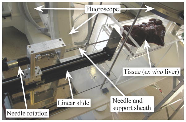
We developed a custom robotic device for inserting and rotating a needle in artificial tissue, similar to the portable version shown in Figure 7. The device inserts a needle into the tissue with a DC motor attached to a linear slide; a second DC motor rotates the needle shaft. A telescoping support sheath prevents the needle outside the tissue from buckling during insertion. During our experiments, images were taken using a pair of XCD-X710 firewire cameras (Sony Corporation, Tokyo, Japan), enabling triangulation of the 3D needle tip position.
Fig. 7.
Our portable needle steering device is designed to fit under a fluoroscope while allowing control of the needle’s insertion and rotation. When using conventional fluoroscopy, only one image plane is available, so the planar controller is unable to determine the height of the needle. Our experimental validation used a similar device that uses two cameras to triangulate the needle tip inside a transparent artificial tissue. Clinical procedures will use bi-plane fluoroscopy or 3D ultrasound to directly measure the needle tip position inside the tissue.
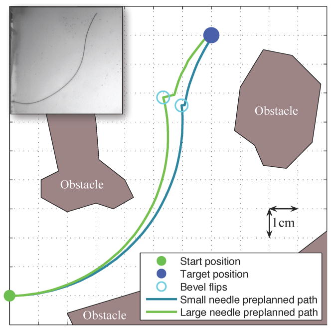
We defined the workspace as an 11×11 cm rectangle in the x-y plane of interest. Obstacles in the workspace were defined by (possibly nonconvex) polygons and the target was defined by a 3D point. Figure 5 shows the workspace and a preplanned path for each needle. Each insertion was stopped when it reached (or passed) the target. The insertions were approximately 14 cm in length, but varied by 2 cm depending on the exact path of the needle.
Fig. 5.
The paths generated by the SMR planner prior to inserting each needle show that both the small and large needles can reach the target while avoiding the obstacles with only one bevel flip. The large needle is thicker, which requires a larger pre-bend at the tip to achieve a similar radius of curvature as the small needle. However, the larger pre-bend causes a discontinuity in the path when the needle rotates. This illustration is an ideal case, but the needle motion varies, so the needle frequently deviates from this path. The inset shows the standard configuration small needle inserted into the artificial tissue.
Nine configurations were tested by changing one variable at a time from the standard configuration. The parameters in the standard configuration are the result of years of individual tuning by the research groups involved in this project and, thus, are expected to show the best performance. These nine configurations were chosen to assess the system performance when individual components are no longer optimally tuned. Each configuration was tested at least five times and the average distance from the target was recorded. All parameters are the same as in the “standard” configuration, except as specified below.
Standard: small needle; planner uses the experimentally determined radius of curvature for the small needle; planner runs at 1 cm intervals; insertion speed is 0.25 cm/s; torsion compensation and planar controller are active with experimentally tuned gains.
Standard large needle: large needle; planner uses the experimentally determined radius of curvature for the large needle.
Replan every 0.3 cm: planner runs at 0.3 cm intervals.
No torsion: no torsion compensation.
Large no torsion: large needle; no torsion compensation.
Open loop: planner is only run once before insertion (no real-time re-planning is used).
Slow insertion: insertion speed is 0.125 cm/s (this causes the needle to insert slower, but the planner and controllers run at the standard rates).
Large slow insertion: large needle; the insertion speed is 0.125 cm/s.
Planar controller gains: various planar controller gains were tested.
B. Results and Discussion
Our primary performance metric is the smallest distance between the needle tip and the target. We measure this distance in 2D (in-plane error, in the plane in which the SMR planner operates), 1D (out-of-plane error, the distance away from the plane), and in 3D (total error, computed from the 1D and 2D errors). Figure 6 shows the final position errors for both needles for eight of the nine experimental configurations. Tables I and II show the average number of bevel flips as well as the 2D and 3D errors. The 3D errors are inherently larger than the 1D and 2D errors. Using the standard configuration, the robotic needle steering system was able to drive the needle into the desired target with sub-centimeter accuracy.
Fig. 6.
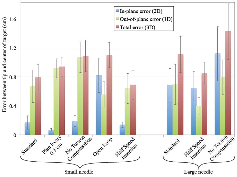
The deviation (Euclidean distance) between the final tip position and the desired target demonstrates how each component of the needle steering system contributes to the goal of driving the needle to the desired target. 2D error indicates deviation within the SMR planner’s plane of motion. 1D error shows how much the tip deviated out of the plane. 3D error shows the combined error. Error bars represent one standard error.
TABLE I.
Distance from target and number of flips in the small needle experiments.
| Standard | Replan Every 0.3 cm | No Torsion | Open Loop Planner | Slow Insertion | |
|---|---|---|---|---|---|
|
| |||||
| 2D error (cm) | 0.18 ± 0.09 | 0.07 ± 0.02 | 0.19 ± 0.08 | 0.82 ± 0.24 | 0.14 ± 0.04 |
| 3D error (cm) | 0.79 ± 0.18 | 0.94 ± 0.13 | 1.09 ± 0.22 | 1.10 ± 0.17 | 0.69 ± 0.20 |
| # of bevel flips | 2.83 ± 0.18 | 5.33 ± 0.68 | 2.20 ± 0.49 | 1.00 ± 0.00 | 5.20 ± 0.91 |
TABLE II.
Distance from target and number of flips in the large needle experiments.
| Standard | Half speed | No Torsion | |
|---|---|---|---|
|
| |||
| 2D error (cm) | 0.69 ± 0.22 | 0.65 ± 0.22 | 1.10 ± 0.37 |
| 3D error (cm) | 1.11 ± 0.25 | 0.85 ± 0.15 | 1.43 ± 0.39 |
| # of bevel flips | 2.29 ± 0.56 | 4.33 ± 0.51 | 4.25 ± 0.67 |
In these experiments, we only varied one parameter for each configuration, which resulted in a cascade of changes throughout the system and a degradation in performance. In the future, a more holistic method for understanding the parametric trade-offs would be useful, but our results suggest that significant modifications of the parameters only affect the total error by a relatively small amount, as depicted in Figure 6. Ideally, one would run an adaptive controller that adjusts the parameters used for control in real-time or use a robust version of these algorithms that do not require precise knowledge of the parameters. Below, we examine the extent of the interactions when changing one parameter at a time.
1) Planar controller gains must be tuned to task-level dynamics
We tested a number of planar controller gains and compared them to the performance of the original gains reported in [14], which were carefully tuned with respect to the task-level dynamics. Experiments performed with significantly more and less aggressive gains failed to reach the target. With more aggressive gains, the planar controller overcorrected, leading to large transients. In some instances, this drove the needle out the top of the tissue (a vertical deviation of more than 2 cm). Once this occurs, control authority is lost and the needle is unable to reach the target. Similarly, inserting without the planar controller or with less aggressive gains resulted in the needle drifting far from the desired plane before the planar controller could correct the motion. These results underscore the importance of tuning gains based on the task-level dynamics. Due to the large errors occurring in many of these trials, the data shown in Figure 6 only uses the optimal gains reported in [14].
2) Update rate affects interaction of planner and controller
Increasing the planner update rate can worsen 3D performance. When the planner is updated every 0.3 cm/s in the small needle, the 2D error is improved, but the 3D error becomes larger. The 2D error is reduced because the planner has more opportunities to correct for the deviations in the needle motion, but this causes an increase in the number of bevel flips. Each bevel flip causes a small out of plane motion. Even with the torsion compensator and planar controller, the vertical position of the needle is worsened. This result highlights the interactions between the various system components – improvements to one component (in this case, the planner) can require that other components (in this case, the planar controller and torsion compensator) face more challenging conditions. The addition of a double cannula [5] to the integrated system could potentially alleviate this specific issue.
3) Intra-operative re-planning improves 2D performance
Eliminating the real-time planner update (i.e., using only pre-operative planning) had the opposite effect as increasing the update rate. This open-loop planning resulted in the largest 2D position error and standard deviation because it could not correct for motions during the insertion. However, the 3D deviation was not much worse since it only had one bevel flip, which the planar controller and torsion compensator could easily handle.
4) Torsion compensation is critical for large pre-bends
Although the large needle had a radius of curvature similar to that of the smaller needle, the large needle was not as accurate as the smaller needle. The larger pre-bent tip created more severe discontinuities when the needle was rotated, which caused larger deviations in both 2D and 3D.
Removing the torsion compensator had a significant effect on the accuracy of the needle and caused a larger out-of-plane and total error in both needles. The torsion compensator is able to help align the needle’s tip to the desired angle and help maintain the planar motion. Torsion compensation had a minimal effect on the small needle’s 2D motion since the needle could still be steered despite the small out-of-plane deviations. However, removing the torsion compensator with the large needle increased the 2D error. The large pre-bend on the large needle prevented the needle from rotating as quickly and the needle tip angle was so misaligned that it affected the radius of curvature in the plane.
5) Decreasing insertion speed improves performance
The insertion speed affects the system in several ways. Based on the 1D, 2D, and 3D errors, the slower insertions were better, but required more time. All the components run at the same frequency, so there is more information per unit distance of insertion. Thus, the planner and planar controller can use the additional images to update and act twice as often with respect to insertion distance. During bevel flips, the additional time allows the rotational dynamics to settle faster relative to insertion distance, so the misaligned needle will have less distance to cause out-of-plane motions. Further, we suspect that the time-constants for the decay of torsional wind-up remain roughly invariant to insertion speed, implying that the effects of torsional lag will decrease for slower insertions [3]. Of course, inserting too slowly will result in increased procedure time, so an appropriate balance needs to be struck. Since an inserted needle interacts with tissue, any needle steering method is subject to similar tissue effects.
V. Proposed Clinical Application
The ultimate goal for robotic needle steering is to enable a clinically relevant task such as biopsy, ablation, or radioactive seed placement. As described earlier, substantial engineering research has demonstrated how to steer and control a needle, but only a few studies have been performed to date demonstrating potential clinical applications of needle steering in real tissue. An example of a brachytherapy with a tip-steered needle has been presented in [4]. A method related to needle steering has been used for tissue ablation [18]. This method consists of controlling the combined effects of thin, curved, concentric tubes to reach a desired location and then inserting an ablation needle though the tubes. Here we describe a proposed steerable-needle-based brachytherapy procedure.
A. Portable System
We developed a portable needle steering device, shown in Figure 7, to demonstrate that robot-assisted needle steering can be achieved under medical imaging, as is necessary for clinical procedures. In Section IV, we showed experimental results of our needle control methods using a stationary robotic system to steer the needle through artificial tissue. The portable and stationary systems are similar in that they both have the two necessary inputs for controlling the needle tip motion: insertion and rotation of the needle shaft. However, the portable system is mobile and able to fit under a fluoroscope. The larger stationary system is mounted to a vibration isolation table and uses a DC motor to generate smoother motions, which allows accurate measurement of the insertion and rotation forces. The portable system uses a stepper motor, which more easily generates accurate motions, but produces less smooth motions, thus complicating insertion-force measurement (used in previous work to validate mechanics-based models [3], [16]).
B. Brachytherapy Procedure
Brachytherapy is a procedure in which radioactive seeds are inserted into cancerous regions via a specially designed needle. A typical brachytherapy needle consists of a sharp stainless steel stylet surrounded by a stainless steel sheath, through which the seeds are introduced into the tissue after needle insertion is complete and the stylet is removed. Brachytherapy is commonly used to treat prostate cancer and is also used to treat cancers found in liver and breast tissues.
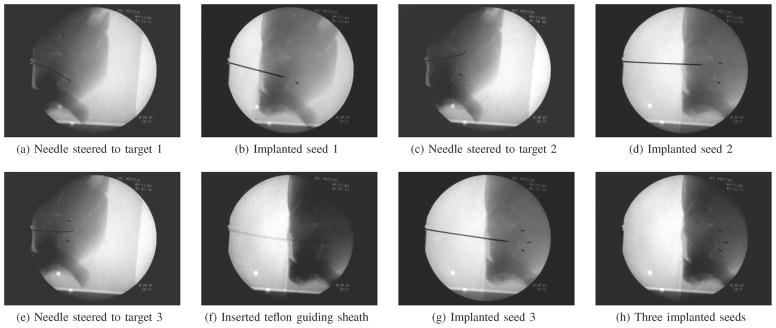
To simulate a clinical procedure, the robot guided a flexible, pre-bent wire to a specific target from a pre-defined insertion location. We used a 0.58 mm diameter Nitinol wire with a 45° bevel angle and a 29° bend in a complementary direction 3 mm from the tip. This insertion location was the same for all insertions. Three different targets were spaced roughly 1.0 cm apart, approximately 5.0 cm away from the insertion point. Once the needle was at the desired target location, a teflon sheath (3.175 mm OD, 1.5875 mm ID) was passed over the needle and the needle was removed from the tissue. Under fluoroscopic guidance, a standard 20-gauge brachytherapy needle was inserted into the teflon guiding sheath and a 1 mm diameter, 4 mm long stainless steel artificial “radioactive seed” was inserted into the tissue. Of the three insertions, two were performed simply by keeping the bend of the needle facing either to the left or to the right. For the last insertion, a path with less curvature was achieved by incrementally inserting and flipping the insertion orientation angle of the needle bend.
Figure 8 shows the process for inserting seeds into a goat liver. We were able to demonstrate that steering inside real tissue is feasible and can be used for clinically relevant procedures. Further study is needed to determine the potential tissue damage arising from this procedure.
Fig. 8.
A brachytherapy procedure was performed in fresh ex vivo goat liver as an example of a clinical needle steering application. First, the steered needle was driven to the desired location for a brachytherapy seed. Next, a sheath was deployed over the needle and the needle was removed. One artificial brachytherapy seed was then inserted through the sheath and deposited at the desired location. The needle was then reinserted, the sheath removed, and the needle was driven to a second location for a seed where this procedure was repeated. In this example, three seeds are placed in target regions approximately 1.0 cm apart.
VI. Needle Steering Challenges and Opportunities
Recent research has resulted in tremendous advances in the steerability of needles, but there are still several areas for future work that need to be addressed before needle steering will be found in clinical practice.
A. Potential for Tissue Damage
Inserting a needle inherently cuts the tissue, which causes damage that can lead to bleeding and swelling. Minor damage is unavoidable with any needle insertion, but steerable needles have the potential to slice through tissue laterally. When a needle is curved in a long arc, the needle presses against the tissue along its length as shown in Figure 9. The insertion force at the base is redirected to the direction tangent to the motion at the tip. The redirection comes from the tissue exerted along the shaft of the needle. If too much force is exerted on the needle shaft, the needle can slice through the tissue.
Fig. 9.
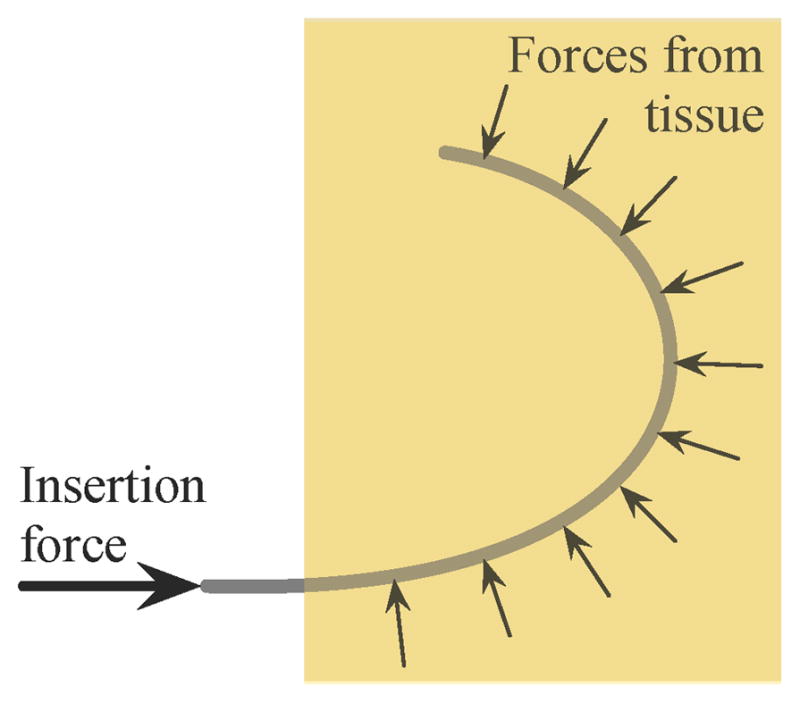
Schematic of the forces that can result in slicing of the tissue. The tissue applies a force perpendicular to the needle shaft, redirecting the insertion force from the base of the needle to the tip of the needle. Too much force will cause the needle to slice through the tissue.
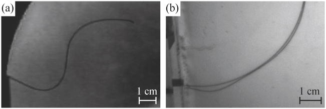
Buckling of the needle inside the tissue is particularly likely to cause the needle to slice the tissue. In experiments with artificial and real tissue, buckling occurred several times. In one instance, the needle encountered a hard region in ex vivo bovine liver that the needle was unable to puncture (Figure 10(a)). Since the needle tip could not go further, the insertion force caused the needle to buckle inside the tissue. Compared to the same insertion prior to buckling (shown in Figure 3), the tip has not moved, but the needle shaft near the entry point has curved downward. Friction along the length of the needle can also cause buckling; for straight-line insertions the friction force increases linearly with depth [3] and friction further increases when the needle curves due to increased normal forces. Figure 10(b) shows a small amount of buckling caused by friction during an insertion into artificial tissue. Buckling also occurs inside the support sheath, but this is not detrimental to the tissue. However, the buckling inside the support sheath could affect the angle of insertion at the base and the insertion force measurement.
Fig. 10.
Examples of buckling inside tissue. (a) The needle tip encountered a hard spot in the bovine liver and, since the tip could no longer move forward, the continued insertion caused the needle to buckle near the insertion point. (b) Two superimposed pictures of the needle during an insertion into artificial tissue showing buckling near the base due to friction along the shaft of the needle.
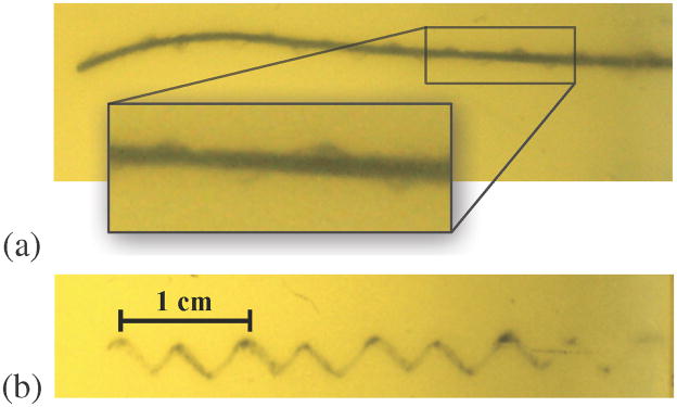
Inserting while rotating a tip-steerable needle can yield a nominally straight needle path. If the needle is rotated slowly relative to the insertion, a corkscrew motion is possible, but undesireable. This effect is not very evident in bevel-tip needles, but can be very obvious in pre-bent needles with small radii of curvature. Figure 11 shows a pre-bent needle after insertion with continuous rotation. The cut rotational path is clear in these images. It is currently unclear whether such a path causes significantly more damage to the tissue than a straight line path. For a pre-bent needle, retracting without “unrotating” (opposite to what was done during insertion), as well as rotating without translating, will likely cause more tissue damage than for bevel-tip needles. An adjustable tip needle [5] could likely alleviate this issue.
Fig. 11.
Extreme examples of a corkscrew pattern resulting from a needle being inserted while slowly rotating and retracting inside an artificial tissue. (a) The needle was inserted while spinning slowly; notice the cut tissue surrounding the needle in a corkscrew pattern. (b) When the needle was retracted, these helical motions were left cut in the tissue.
Models of the stress/strain needles apply to tissue as well as studies in live tissue are needed to identify needle paths likely to cause tissue damage and determine the extent to which this damage could affect patient outcomes. All surgery involves damaging tissue to some extent, but the clinical significance of the type of damage that may occur during needle steering are unknown.
B. Tissue Membranes
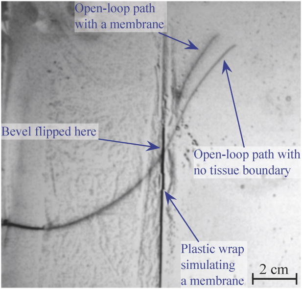
A needle that encounters a membrane perpendicular to the direction of tip motion will likely continue along the desired path after it punctures the membrane, assuming buckling does not occur. However, if the angle between the needle and the membrane is shallow, the needle is likely to slide along the membrane and alter its path significantly. Figure 12 shows how such a membrane alters the path of the small needle (described in Section IV). Both of these paths were achieved using open loop control, so the single bevel flip occurred at the same location. Note that the paths are nearly identical until they encounter our simulated membrane (a thin plastic wrap embedded in artificial tissue). When in contact with the membrane, the needle tip moved along, but not into, the membrane. The membrane resulted in a final tip location differing by more than 1 cm from the tip position from an insertion without the membrane.
Fig. 12.
An image of a needle inserted through a membrane is superimposed over an image of needle insertion without the membrane. To simulate a membrane, we created an interface between two artificial tissues using plastic wrap. Depending on the orientation of the needle upon reaching this membrane, the needle can be steered off course.
C. Complete Mechanics-Based Modeling
Throughout this article, we have mentioned “experimentally” determined gains and parameters. This method works well for experimental validation, but tuning these parameters during a real clinical procedure would require extra needle insertions. Such additional insertions would contradict the goal of treatment with less tissue trauma. Thus, it is vital for researchers to develop a fundamental understanding of needle-tissue interaction mechanics. Recent work [16] using dimensional analysis has determined the tissue parameters most important for describing the needle motion inside tissues, and there exist preliminary models to predict the radius of curvature based on needle and tissue mechanical and geometric properties. Such models must be extended to incorporate tissue inhomogeneities and anisotropies, including membranes and multiple tissue layers. In addition, emerging imaging technologies such as elastography may enable noninvasive tissue property measurement.
D. Planning in 3D with Uncertainty
The motion planner used in the experiment presented here assumed that needle motion was restricted to a 2D plane. This is appropriate when only 2D imaging is available (like 2D ultrasound) since planning motions that avoid obstacles requires that those obstacles are visible and can be segmented. As 3D intra-operative imaging becomes more prevalent (3D ultrasound, MRI), we would like the planner to utilize this information and compute motions through 3D space to reach a clinical target while avoiding obstacles. Although several motion planning algorithms have been developed to compute optimal trajectories for bevel tip-steerable needles in 3D environments [19], [20], key open challenges remain, including planning 3D paths that consider motion and sensing uncertainty as well as compensating for the effects of 3D tissue deformation.
E. Human-in-the-Loop Control
For our needle steering system, the human operator has only partially been in the control loop, mainly to observe and stop the procedure if anything goes wrong. To be clinically viable, the human operator will need to have significantly more control over the system. The human operator should be in control of the insertion speed for safety and be able to indicate or choose the needle path with help from a path planner. Romano et al. [21] compared manual teleoperation to automatic needle insertion and showed that hybrid control in which the human operator controlled the speed of the insertion and the computer controlled the needle rotation provided improved accuracy over complete human control. However, visualization for the operator is an open issue; it is difficult to display a complex needle path in an intuitive manner.
F. Radius of Curvature
Although simulation studies have provided very compelling examples of the potential capabilities of high-curvature steerable needles, in practice the achievable curvature is limited. For some clinical applications, particularly when the organ is small, there are a great number of obstacles to avoid, and/or the insertion location is highly constrained. The current minimum radius of curvature achieved experimentally is 1.5 cm in artificial tissue and is 3.4 cm in real tissue (liver) [4]. As mentioned earlier, enhanced steerability can result from a combination of needle steering methods, including asymmetric-tip steering, needle base manipulation, and tissue manipulation. However, there are currently no systems that incorporate multiple methods to drive a needle to a target. To reach many desirable target locations inside the body, better steerability may need to be achieved.
VII. Conclusions
This article briefly reviewed key aspects of the state-of-the-art in robot-assisted needle steering and describes the development and evaluation of a complete asymmetric-tip needle steering system that integrates multiple controllers and path planners to drive a needle to a desired location. We have shown how this system could be used to perform a brachytherapy procedure in real ex vivo tissue and highlighted a number of opportunities for further research and development in this field. The eventual clinical success of needle steering depends on solving these open problems and reducing needle steering system components to practice in a driving application to create a fully integrated clinical needle steering system.
Needle steering is an ideal problem to both drive fundamental robotics research (e.g., in the areas of planning and control) and push the boundaries of semi-autonomous and autonomous computer-assisted medical interventions. Needle steering research integrates many key features that give robot-assisted surgery and radiology such great potential for improving accuracy while decreasing invasiveness. This includes (1) quantitative descriptions of patient state, (2) the use of models for planning, (3) the design of devices and control systems that connect information to physical action in a manner appropriate for a medical procedure, and (4) the incorporation of human user input in a natural way.
Acknowledgments
The authors thank current and former collaborators on this project for their contributions: Dr. Greg Chirikjian, Dr. Gabor Fichtinger, Dr. Michael Choti, Dr. Danny Song, Dr. K. T. Ramesh, Dr. Russell Taylor, Dr. Robert Webster, Dr. Wooram Park, Dr. Jin Seob Kim, Dr. Vincent Duindam, Dr. Jijie Xu, Dr. Kris Hauser, Dr. Sarthak Misra, John Swensen, and Thomas Wedlick.
Footnotes
Portions of this work previously presented at the IEEE/RAS-EMBS International Conference on Biomedical Robotics and Biomechatronics in 2008.
References
- 1.Webster RJ, III, Kim JS, Cowan NJ, Chirikjian GS, Okamura AM. Nonholonomic modeling of needle steering. Int J Robot Res. 2006;25(5–6):509–525. [Google Scholar]
- 2.Alterovitz R, Goldberg K. Springer Tracts in Advanced Robotics. Springer; 2008. Motion Planning in Medicine: Optimization and Simulation Algorithms for Image-Guided Procedures; p. 50. [Google Scholar]
- 3.Reed KB, Okamura AM, Cowan NJ. Modeling and control of needles with torsional friction. IEEE Trans Biomed Eng. 2009;56(12):2905–2916. doi: 10.1109/TBME.2009.2029240. [DOI] [PMC free article] [PubMed] [Google Scholar]
- 4.Majewicz A, Wedlick TR, Reed KB, Okamura AM. Evaluation of robotic needle steering in ex vivo tissue. IEEE Int Conf Robot Autom. 2010 May;:2068–2073. doi: 10.1109/ROBOT.2010.5509873. [DOI] [PMC free article] [PubMed] [Google Scholar]
- 5.Okazawa S, Ebrahimi R, Chuang J, Salcudean SE, Rohling R. Hand-held steerable needle device. IEEE/ASME Trans Mech. 2005;10(3):285–296. [Google Scholar]
- 6.Minhas DS, Engh JA, Fenske MM, Riviere CN. Modeling of needle steering via duty-cycled spinning. Conf of the IEEE EMBS. 2007:2756–2759. doi: 10.1109/IEMBS.2007.4352899. [DOI] [PubMed] [Google Scholar]
- 7.Abolhassani N, Patel R, Moallem M. Needle insertion into soft tissue: A survey. Med Engineering and Physics. 2007;29:413–431. doi: 10.1016/j.medengphy.2006.07.003. [DOI] [PubMed] [Google Scholar]
- 8.DiMaio SP, Salcudean SE. Needle steering and motion planning in soft tissues. IEEE Trans Biomed Eng. 2005 Jun;52(6):965–974. doi: 10.1109/TBME.2005.846734. [DOI] [PubMed] [Google Scholar]
- 9.Glozman D, Shoham M. Image-guided robotic flexible needle steering. IEEE Trans Robotics. 2007 Jun;23(3):459–467. [Google Scholar]
- 10.Mallapragada VG, Sarkar N, Podder TK. Robot-assisted real-time tumor manipulation for breast biopsy. IEEE Transactions on Robotics. 2009;25(2):316–324. [Google Scholar]
- 11.Torabi M, Hauser K, Alterovitz R, Duindam V, Goldberg K. Guiding medical needles using single-point tissue manipulation. Proc IEEE Int Conf Robot Autom. 2009:2705–2710. [Google Scholar]
- 12.Alterovitz R, Branicky M, Goldberg K. Motion planning under uncertainty for image-guided medical needle steering. Int J Robot Res. 2008 Nov;27(11–12):1361–1374. doi: 10.1177/0278364908097661. [DOI] [PMC free article] [PubMed] [Google Scholar]
- 13.Reed KB, Kallem V, Alterovitz R, Goldberg K, Okamura AM, Cowan NJ. Integrated planning and image-guided control for planar needle-steering. Proc IEEE Conf Biorob. 2008:819–824. doi: 10.1109/BIOROB.2008.4762833. [DOI] [PMC free article] [PubMed] [Google Scholar]
- 14.Kallem V, Cowan NJ. Image guidance of flexible tip-steerable needles. IEEE Trans Robot. 2009;25(1):191–196. doi: 10.1109/TRO.2008.2010357. [DOI] [PMC free article] [PubMed] [Google Scholar]
- 15.Park W, Reed KB, Okamura AM, Chirikjian GS. Estimation of model parameters for steerable needles. Proc IEEE Int Conf Robot Autom. 2010 May;:3703–2708. doi: 10.1109/ROBOT.2010.5509380. [DOI] [PMC free article] [PubMed] [Google Scholar]
- 16.Misra S, Reed KB, Schafer BW, Ramesh KT, Okamura AM. Mechanics of flexible needles robotically steered through soft tissues. Int J Robot Res. 2010;29(13) doi: 10.1177/0278364910369714. [DOI] [PMC free article] [PubMed] [Google Scholar]
- 17.Krouskop T, Wheeler T, Kallel F, Garra B, Hall T. Elastic moduli of breast and prostate tisues under compression. Ultrasonic Imaging. 1998;20:260–274. doi: 10.1177/016173469802000403. [DOI] [PubMed] [Google Scholar]
- 18.Burdette EC, Rucker DC, Prakash P, Diederich CJ, Croom JM, Clarke C, Stolka PJ, Juang T, Boctor EM, Webster RJ., III The ACUSSIT ultrasonic ablator: The first steerable needle with an integrated interventional tool. SPIE Medical Imaging. 2010 Feb; [Google Scholar]
- 19.Park W, Wang Y, Chirikjian GS. The Path-of-probability Algorithm for Steering and Feedback Control of Flexible Needles. Int J Robot Res. 2010;29:813–830. doi: 10.1177/0278364909357228. [DOI] [PMC free article] [PubMed] [Google Scholar]
- 20.Duindam V, Xu J, Alterovitz R, Sastry S, Goldberg K. Three-dimensional Motion Planning Algorithms for Steerable Needles Using Inverse Kinematics. Int J Robot Res. 2010;29(7):789–800. doi: 10.1007/978-3-642-00312-7_33. [DOI] [PMC free article] [PubMed] [Google Scholar]
- 21.Romano JM, Webster RJ, III, Okamura AM. Teleoperation of steerable needles. Proc IEEE Int Conf Robot Autom. 2007 Apr;:934–939. [Google Scholar]


