Abstract
We present a straightforward microfluidics system to achieve step-by-step reaction sequences in a diffusion-controlled manner in quasi two-dimensional micro-confinements. We demonstrate the hierarchical self-organization of actin (actin monomers—entangled networks of filaments—networks of bundles) in a reversible fashion by tuning the ion concentration in the system. We show that actin can form networks of bundles in the presence of without any cross-linking proteins. The properties of these networks are influenced by the confinement geometry. In square microchambers we predominantly find rectangular networks, whereas triangular meshes are predominantly found in circular chambers.
INTRODUCTION
Actin, intermediate filaments, and microtubules are the three main building blocks of the cytoskeleton. Along with numerous accessory proteins like cross-linkers and motors, they together form three-dimensional composite networks.1 The composition as well as the architecture of these networks are essential in determining their mechanical properties. Actin as well as microtubules have a strong potential to form self-organized structures in presence of accessory proteins. Steady-state aster-like structures have been reported for adenosine triphosphate (ATP) depleted actin-myosin system,2 supported by numerical studies.3 Networks and clusters of actin bundles are observed at high concentrations of different cross-linkers such as espin, fascin, α-actinin, and filamin.4 Self-organized asters emerge in actin-myosin-fascin5 and actin-Arp2/3 complex-fascin6 systems. Microtubule-motor systems also self-organize into asters, vortices, and networks7 and the self-organization is influenced by the size of the confinement.8 In all these experiments, the factors responsible for self-organization—cross-linking or motor proteins—were present from the beginning and were not added or depleted in a stepwise manner.
Microfluidics systems have been successfully used to investigate the dynamics of single actin filaments in flow and confinement using microchannels of various dimensions.9, 10, 11 Micropatterning of actin nucleation promoting factors has shown to strongly affect the self-organization of actin.12 Also, self-assembly of actin bundles in confined geometries has been reported using narrow microfluidic channels.13 In order to study hierarchical self-assembling systems like actin, which can be in different states (monomers, filaments, and networks), it is essential to have a flow-free environment in order to eliminate any possible effect on the structure formation due to induced flow fields. Some of the common procedures to eliminate possible flow are confining the actin solution in between two glass coverslips and sealing them with vacuum grease2, 14 or using hermetically sealed chambers.15 However, with such systems, the composition remains fixed as it is not possible to add or deplete materials from the system without physically (mainly induced flow fields) affecting it.
Composite microfluidics devices consisting of a membrane between two fluid streams allowing diffusive mass transport through it can be designed.16 However, small membrane pores can cause serious problems for polymer systems, especially membrane clogging, while bigger membrane pores increase advective transport across the membrane. Efforts have been made to achieve step-by-step reaction schemes in cell-sized liposomes, by embedding protein pores in the membrane17 or by ionophore-mediated influx of .18 Still, such systems are limited to transport of small molecules. Also, it is not possible to revert back to the original state.
Association of polyelectrolytes by linkers is an important biological process (DNA condensation, self-assembly of actin filaments) and has been well studied.19, 20, 21 In case of actin, the bundles can be disassembled (“de-bundling”) by decreasing the bundling agent concentration, which has been addressed theoretically,22 or by changing the association-dissociation equilibrium between actin filaments and the bundling agent.23 In this context, being able to tune the chemical composition (stepwise addition or depletion of the involved components) is an obvious advantage. Moreover, mixing of all components at once in comparison to a stepwise addition of components to a pre-formed steady-state system may lead to completely different results. To achieve such step-by-step reaction sequences, we have designed a microfluidics system consisting of micro-confinements, termed “microchambers,” in which a minimal system of actin filaments can be confined and the reaction conditions can be changed (for example, concentration of ions) in a stepwise manner as required.
In this paper, we first describe the design and the working principle of the “microchambers.” Then, we show how a stepwise addition or depletion of materials leads to hierarchical self-assembly and disassembly of actin. We use multivalent cations () as bundling agents and show how actin filaments are confined in microchambers to form an entangled actin network, get bundled and de-bundled by tuning the concentration of ions in the system. Lastly, we discuss a special case where actin filaments self-organize into stable networks comprising of actin bundles in response to the gradual increase in the concentration of actin and facilitated by evaporation. We demonstrate the effect of confining geometries, squares and circles, on the formation of these networks and their properties.
MATERIALS AND METHODS
Materials
Actin from rabbit skeletal muscle, fluorescent Atto488-Actin from rabbit skeletal muscle, polymerization buffer (1M KCl, 0.1M imidazole pH 7.4, 10 mM ATP, 20 mM ) and dilution buffer (2 mM Tris-HCl pH 8.2, 0.4 mM ATP, 0.1 mM , 1 mM DTT (dithiotreitol)) are purchased from Hypermol EK. To induce actin polymerization, polymerization buffer is added to the actin solution in 1:9 ratio. Final composition of the actin solution is 3 μM actin, 1.4 mM ATP, 100 mM KCl, 2 mM , 0.1 mM , 0.02 mM , 0.4 mM DTT, 10 mM imidazole, 1.8 mM Tris-Cl pH 7.4, and 0.03% disaccharides. Actin:Atto488-actin ratio is either 5:1 or 10:1. Anhydrous is purchased from Sigma-Aldrich (St. Louis, USA). Multi-fluorescent microspheres are purchased from Polysciences Europe GmbH (Eppelheim, Germany).
Photolithography
Standard photolithography is performed using SU8 negative resists (Microchem, Newton, MA, USA) spin coated on silicon wafers (Si-Mat, Kaufering, Germany) to fabricate masters for further device production. In order to produce multi-height devices, multi-layer photolithography is carried out using appropriate photomasks (JD Pho-tools, Oldham, UK) and a MJB4 mask aligner (SUSS MicroTec AG, Garching, Germany). To produce a master with a controlling channel 4 in height and the microchambers 2 in height, two layers of SU8-2002 are used. To produce a master with a controlling channel 10.5 in height and the microchambers 0.5 in height, first layer is of SU8-2000.5 and second one is of SU8-3005. It should be noted that the different heights of the microchambers do not affect the outcome of the experiments. Polydimethylsiloxane (PDMS) and cross-linker (Sylgard 184, Dow Corning GmbH, Wiesbaden, Germany) are mixed in the mass ratio 10:1, degassed and poured on the masters followed by baking at for at least 4 h. Cured PDMS is peeled off from the wafer, punched (to insert the tubings later on), cleaned with isopropanol, dried with nitrogen, and then covalently bonded to a clean glass slide after plasma treatment at 2 mbar for 30–40 s in a plasma cleaner (Harrick Plasma, NY, USA).
Pre-treatment of the devices
PDMS is permeable to water which results in permeation-driven flow and also increases the concentration of confined materials. In order to prevent this, the device is submerged in water for at least 24 h before as well as during the experiments. We have taken advantage of the evaporation of water through PDMS in the experiments of Sec. 5 in order to gradually increase the concentration of actin and salts. In this case, the device is not saturated with water before or during the experiments to facilitate evaporation. The increase in the concentration of actin and salts due to evaporation is estimated by carrying out experiments with the same set-up using 0.2 diameter fluorescent microspheres instead of actin.
In order to prevent actin from sticking to the channel and microchamber walls, the device is first rinsed with 1 mg/ml PLL(20)-g[3.5]-PEG(2) (SuSoS AG, Dübendorf, Switzerland) for at least half an hour and subsequently rinsed with water.
Microscopy
An Olympus IX81 inverted microscope equipped with a fluorescence illumination (X-Cite Series 120 Q) and a 40 x (N.A. 1.30) UPlanFL N oil immersion objective (Olympus, Tokyo, Japan) are used to perform experiments. The images are recorded with a SensiCam (PCO AG, Kelheim, Germany) and a camware software with exposure times of 3–10 ms.
Image processing and analysis
Image processing is done using a combination of imagej and matlab (R2009a, The MathWorks). Fluorescent images are appropriately thresholded, binarized, and finally skeletonized for further image processing and analyses. Processed images are further analysed using self-written macros in matlab and imagej. For better visualization, all fluorescent images in this paper are inverted so that fluorescent actin appears darker against a lighter background.
MICROCHAMBERS
The design
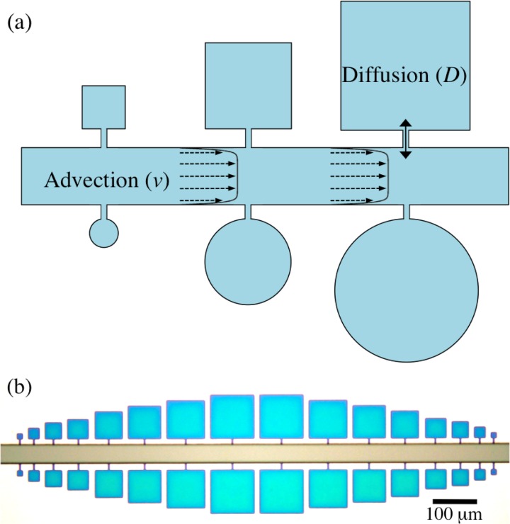
We have designed a straightforward microfluidics system consisting of micro-confinements of different geometries with the possibility of adding and depleting materials in a diffusion-controlled fashion (Fig. 1). These micro-confinements or “microchambers” are connected to a main controlling channel via narrow connecting channels, as can be seen in Fig. 1a. The fluid of interest flows by advection through the controlling channel, which is rectangular in cross-section. As one approaches the wall, the velocity decays to zero according to no slip boundary condition and obeys the following equation for the velocity field in a channel with rectangular cross-section and a low aspect ratio (height to width, ),24
| (1) |
where is the pressure difference between the two ends of the controlling channel, L is the controlling channel length, and η is the viscosity of the liquid. Note that the flow profile is a plug flow owing to the low aspect ratio of the channel. Also, since the height and the width of the connecting channels are much less than that of the controlling channel, the velocity field is virtually unaffected by the protrusions, i.e., the connecting channels at the side walls. As a result, material transport from the controlling channel into the microchambers and vice versa is governed by diffusion. The advective transport into the microchambers is further prevented by a multi-height approach. The master is produced using multi-layer photolithography which makes the height of the controlling channel bigger than that of the microchambers and connecting channels. This height difference further minimizes any possible microflow into the chamber to a great extent as the hydraulic resistance () of the channels is inversely proportional to third power of the channel height (h).
| (2) |
Figure 1.
(a) Schematic representation of the microfluidic devices consisting of microchambers. (b) Bright field image of a master prepared using photolithography showing an array of square microchambers. The fact that the device is multi-height is evident by the different colours for the controlling channel (h = 10.5 ) and for the microchambers and connecting channels (h = 0.5 ).
A part of the master showing an array of square microchambers is shown in Fig. 1b. The device has a 40 wide controlling channel. Microchambers are connected to it by small connecting channels. Square microchambers vary in size from 12.5 × 12.5 to 100 × 100 with an increment of 12.5 while circular microchambers vary from 10 to 70 in diameter with an increment of 10 . The small height (0.5–2 ) of microchambers suggests that they can be considered as quasi two-dimensional systems. Thus, the system consists of an advection-dominated controlling channel to which diffusion-dominated microchambers are connected.25
Diffusive behaviour in microchambers
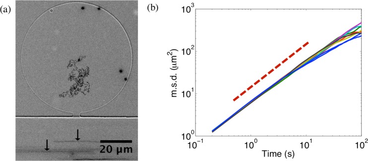
Advection in the controlling channel and diffusion in microchambers can furthermore be clearly seen when multi-fluorescent microspheres are injected in the device and their trajectories are recorded by fluorescence microscopy (Fig. 2a). Arrows in the controlling channel point to the streaks of microspheres flowing by advection, while the trajectory inside the microchamber shows a typical displacement of a diffusing particle. Mean square displacement (msd) of a trajectory linearly increases with time for diffusion . Fig. 2b shows a plot of msds of several microspheres fluctuating inside microchambers of different shapes and sizes against time. The msds have slopes near 1 (dashed line has a slope of 1) indicating diffusive behaviour in the microchambers. Minute impact of bead collisions with the microchamber walls is observable for long observation times.
Figure 2.
(a) A circular microchamber with a height of 2 containing freely fluctuating fluorescent microspheres (0.2 diameter). Trajectory of one of the beads is shown. In the controlling channel, streaks of beads flowing by (indicated by arrows) can be seen indicating advection. (b) Log-log plot showing several typical msds of microspheres inside the microchambers of different geometries. The dashed line has a slope of 1.
To summarize, microchambers can be described as diffusion-controlled, flow-free confined systems.
CONTROLLED BUNDLING AND DE-BUNDLING OF ACTIN FILAMENTS
A schematic representation of the functioning of microchambers is given in Fig. 3. When an actin solution along with polymerization buffer is injected in the controlling channel, actin monomers (G-actin) diffuse into the microchambers along with ions. Once actin polymerization is initiated, the formed filaments are confined inside the microchambers due to their increased size, which lowers their diffusion coefficient in comparison to monomers and additionally hinders the transit through the narrow connecting channels. Actin also polymerizes in the controlling channel, but these filaments are washed away to the outlet by advection. Since the microchambers are in contact with the controlling channel, G-actin and ions freely diffuse in and out of them and their concentrations in the microchambers essentially remain the same as in the controlling channel. The concentration of filaments inside the microchambers reaches a steady state resulting in an entangled network of actin filaments which can be followed by a constant mean fluorescence intensity in the microchambers. Such a network can be further manipulated as intended. Here, we show bundling and de-bundling of actin filaments as an example. As actin filaments have a negative linear charge density of approximately , polycations (in the mM range) can serve as cross-linkers by compensating the electrostatic repulsion between the filaments by enhanced charge condensation, and a sharp bundling transition is observed.20 Bundle assembly and disassembly can be controlled by varying the cross-linker concentration since bundling as well as de-bundling take place at a finite cross-linker concentration.22 When ions are added to the controlling channel, confined actin filaments should undergo a bundling transition to form several bundles which will ultimately fuse together to give rise to a network of actin bundles. Since the transport in and out of microchambers is diffusion-controlled, added salts can also be depleted from the system. Lowering the concentration should then lead to de-bundling and restore the entangled actin filament network. In this way, confined actin filaments can be manipulated simply by changing the composition of the main fluid stream.
Figure 3.
Scheme showing entangled actin network formation inside the microchamber by addition of ATP and ions, followed by bundling and de-bundling by respectively adding and depleting ions.
Fig. 4 shows that the aforementioned working principle can be experimentally realized inside microchambers. Introducing actin solution in a pre-coated and water equilibrated device results in an entangled network of single actin filaments in microchambers. The flow rate in the controlling channel is kept very low, around with the help of a syringe pump (cetoni GmbH, Korbussen, Germany). Polymerized filaments freely fluctuate inside the microchambers and do not stick to the walls. Addition of 50 mM to the actin solution in the controlling channel induces bundling of the entangled network of actin filaments. Formed bundles join in order to generate a network of bundles. The bundling transition is sudden, in the order of few minutes. The network of bundles does not stick to the walls but fluctuates as a single entity. This observation is a strong indication that the bundles are joined at the nodes and are not just overlapping. The network of actin bundles can further be de-bundled by flushing the controlling channel with actin solution having only residual 2 mM . De-bundling is a slower process which can take up to a few hours till the system is restored to the original configuration of entangled actin filaments. This effect is prominently seen with thicker bundles and nodes with higher connectivity, which may take several hours until they completely de-bundle. This slower process may be caused by a discontinuous de-bundling transition, in analogy to the theoretical model by Kierfeld et al.22 Further bundling of the entangled filaments can be induced within minutes by again adding 50 mM to the actin solution in the controlling channel. Thus, the bundling de-bundling cycle can be efficiently repeated.
Figure 4.
Two consecutive cycles of bundling and de-bundling of confined entangled actin filaments inside a microchamber (h = 0.5 ) by addition and subsequent depletion of 50 mM . The microchamber walls and the connecting channel are highlighted by dashed lines.
EVAPORATION INDUCED NETWORK FORMATIONS OF ACTIN BUNDLES
Experimental
Permeability of PDMS to water is a nuisance for proper functioning of microfluidic devices but it has also been successfully employed to achieve evaporation-driven pumping,26 sample concentration,27, 28 or even crystallization.29 We use the permeability of PDMS to water as means of sample concentrator by not equilibrating the device with water before or during the experiment. This leads to gradual evaporation of water throughout the device—controlling channels as well as the microchambers. The increased concentration of actin and divalent cations ( and ) induces actin bundling.
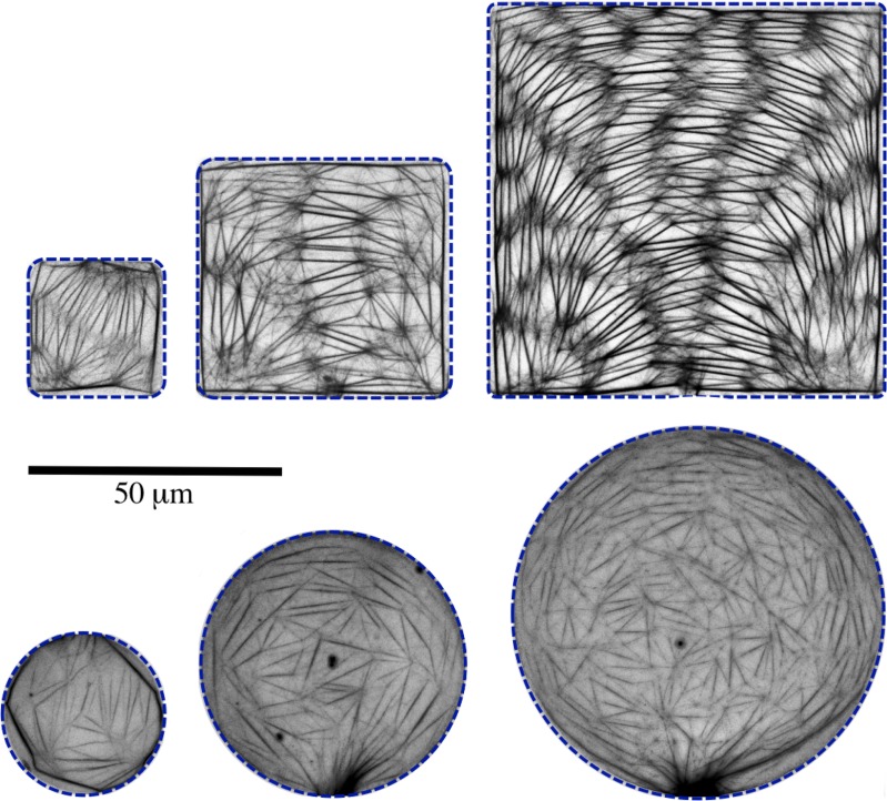
The gradual evaporation indeed not only induces bundle formation, but results in fascinating and complex networks of actin bundles inside the microchambers in about 20 h (Fig. 5). The obtained networks are formed without any cross-linking proteins and the bundling is mainly induced by since the initial concentration is much higher than the initial concentration ([] = 2 mM, [] = 0.1 mM, []/[] = 20). Though water loss occurs through the entire device, the confined and almost flow-free environment of microchambers strongly favours the formation of regular actin networks. Bundles are also formed in the controlling channel and may get connected with the networks in microchambers (the dark actin bundle patches at the periphery of some of the circular microchambers in Fig. 5), but without severely affecting the network geometry. We observe a 50-100 fold increase in the concentration of actin and salts due to evaporation during a 20 h period.
Figure 5.
Fluorescence images of actin bundle networks formed inside square and circular microchambers of different sizes (h = 2 ). Microchamber walls are highlighted by dashed lines. Each image is a 2-D projection of a z-stack of 40 images with a step size of 50 nm.
Networks of actin bundles
The bundle networks are made up of links which join each other to form nodes (Fig. 5). The links are made up of actin bundles of varying thickness. The number of links increases approximately linearly along with the increase in the volume of microchambers, indicative of the fact that the concentration of materials in all the microchambers is essentially the same. Nodes are formed when two or more actin bundles fuse with each other. A detailed look at the nodes reveals a complex architecture (Fig. 6). Nodes are not just single points but rather elaborate structures. Numerous short actin bundles and single actin filaments fuse with thicker main links to form a fine mesh at each node.
Figure 6.
25% of the central area in 100 × 100 square microchamber (a) is enlarged in the next images (respectively in b, c, and d) to reveal the complex architecture at the nodes.
An important factor in the formation process of such networks is that an entangled network of single actin filaments is formed before the bundling is initiated by the increase in the actin and concentrations. If a high, bundling inducing concentration of is present from the beginning, bundling is induced right from the start and networks with only few links are formed which do not evolve further. Thus, an initial formation of entangled actin filaments is necessary before the bundling events in order to generate actin networks with high complexity.
Network properties
We analyze the formed meshes in terms of their areas and shapes, link lengths, and orientations. Networks in square and circular microchambers look qualitatively different (Fig. 5) and we compare these properties for the two confinement geometries as well.
Shape and area of meshes
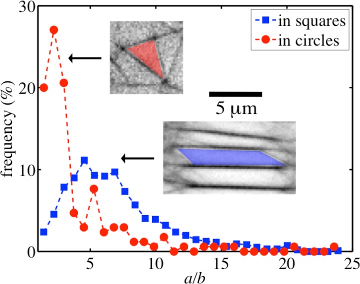
Meshes formed by the networks in square microchambers are different from those formed by the networks in circular microchambers, especially with respect to their architecture and symmetry. The mean mesh area is ( for meshes in circular microchambers and () for meshes in square microchambers and are thus comparable. This is an indication of equal actin bundle density in all the microchambers irrespective of their geometry. In square confinements, meshes are in general elongated and have rectangular geometry, whereas meshes in circular confinements have triangular geometry and are less elongated. To quantify these observations, we fit the meshes with ellipses, which have the same normalized second moments. We use the ratio of major axis length a to the minor axis length b of the ellipse as a shape parameter for the corresponding mesh (). Frequency distributions of a/b for meshes formed in square and circular microchambers are shown in Fig. 7. As can be seen, a/b value has a peak around 2 for meshes in circular microchambers suggesting less elongated, triangular geometries and a peak around 5 for meshes in square microchambers suggesting more elongated, rectangular geometries.
Figure 7.
Frequency distributions of a/b, where a is the length of major axis and b is the length of minor axis of an ellipse having the same normalized second moment as the corresponding mesh in circular (red circles) and square (blue squares) microchambers. The insets show typical mesh geometries in circular and square microchambers.
Link lengths
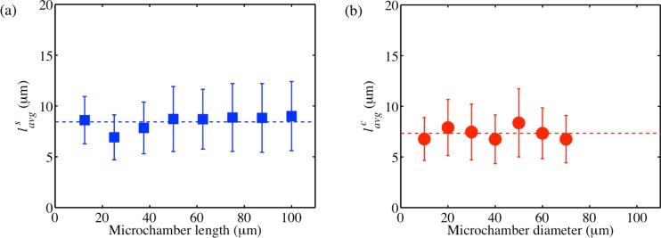
Link lengths (l) are the lengths of actin bundles before they join other actin bundles to form nodes. Fig. 8 shows the average link lengths for square and circular microchambers of different sizes. The link lengths show only small variations with respect to the confinement sizes. The average link length in square microchambers is 8.4 while the average link length in circular microchambers is 7.3 . Thus, the link lengths are comparable for different confinement shapes. This suggests that the link length (l) is a characteristic of the system independent of the confinement geometry and depending only on the composition of the system.
Figure 8.
Average link lengths () of actin bundle networks formed in square (a) and circular (b) microchambers of different sizes. Dashed horizontal lines in each of the plots represent the average link length for all of the sizes. The error bars indicate ± standard deviation.
Link orientations
The angle subtended by links with respect to a reference line refers to the link orientations. We define the long axis of the controlling channel as the reference line and accordingly calculate the link orientations. Thus, the orientations range from to , which are mirrored to get the whole angle spectrum from to and give us an idea about the possible symmetry patterns formed by the networks.
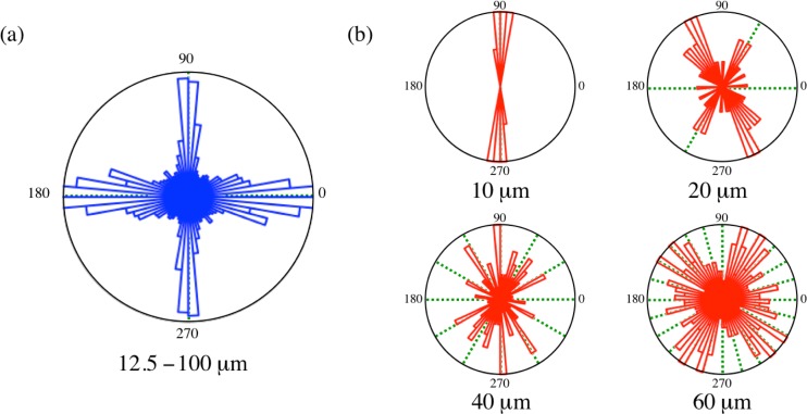
In general, links in square microchambers are predominantly aligned parallel to the microchamber boundaries, thus showing four maxima in the orientation distribution (Fig. 9a). This tendency becomes stronger as the microchamber size increases. Links in square confinements thus show a 4-fold rotational symmetry meaning rotation of resulting in the same symmetry pattern as the original one. This reflects the tendency of network links to get oriented along the boundaries of the confinements. The distribution is a bit broader around and and may be due to partial “arch-like” structures of the links observed for some of the bigger square microchambers (Fig. 5).
Figure 9.
(a) Orientation distributions of links in square microchambers of all the sizes. (b) Orientation distributions of links in circular microchambers for different sizes as indicated. Dashed lines are drawn for better visualization of the rotational symmetries. Bin width is .
On the other hand, link orientations in circular microchambers show different geometrical patterns. Their orientations strongly depend on the diameter of the confining circular chambers, some of them are shown in Fig. 9b. The orientation distributions show higher rotational symmetries with increasing diameter: 10 diameter microchambers show a strong polar character with a 2-fold symmetry, 20 and 30 microchambers have a polar distribution with a possible 6-fold rotational symmetry, 40 a 12-fold rotational symmetry, 50 an 18-fold rotational symmetry, 60 and 70 diameter a possible 24-fold rotational symmetry. Thus, 6-fold and multiples of 6-fold rotational symmetries are favoured in circular microchambers. It should be noted that there is no impact of the connecting channel on the observed rotational symmetries, see for example the orientation distribution of 20 diameter microchamber in Fig. 9b.
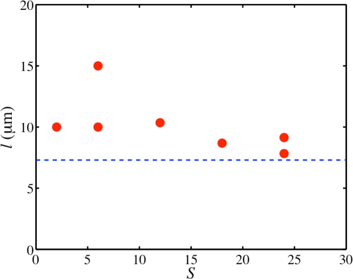
The fact that the link length stays constant and the rotational symmetries increase with the increase in the diameter d suggests that the size of the microchambers plays an important role in determining the rotational symmetry. The length of a chord (l) on a circle with diameter (d) depends on the angle (α) it subtends at the centre as, . Given a rotational symmetry (S), the angle between the chords is expected to be . This gives us an equation for the expected link length based on the observed rotational symmetries as,
| (3) |
Fig. 10 shows the calculated chord lengths l for the observed rotational symmetries in circular chambers of different sizes. As can be seen, values of l mostly vary between 8–10 , showing the same tendency to have a constant value, though a little bit higher than the average link length in circular microchambers ( 7.3 ). The growth of actin bundles parallel to the boundaries for square microchambers, which explains the observed 4-fold rotational symmetry, as well as the dependence of the rotational symmetry on the diameter of circular microchambers, which may explain the almost matching calculated chord and measured link lengths, are indications that the bundling process emerges from the chamber walls. This impact of the walls on the bundling process is observed in case of evaporation induced network formation. In microchambers, the evaporation rate is higher at the boundaries than in the interior, due to the extra surface area of the edge. Thus, it is more probable that the bundling process starts at the boundaries and eventually spreads to the interior. Indeed, we observe that first bundles are formed near the boundaries. As a bundle forms, the concentration of actin in its vicinity suddenly drops since the actin is used up in forming the bundle. This may set a specific distance for the next bundle to form, which should be only dependent on the concentration of materials, which is same in all confining geometries. Since bundling can simultaneously start from different positions along the walls, growing bundles will eventually meet, giving rise to nodes and resulting in a consistent link length. Due to the different chamber geometries, elongated rectangular meshes are predominantly found in square microchambers, whereas triangular meshes are predominantly found in circular microchambers.
Figure 10.
A plot of calculated link lengths () for the observed rotational symmetries (S) in circular microchamber of different diameters. The horizontal dashed line represents the average link length in circular microchambers, 7.3 .
DISCUSSION AND OUTLOOK
We have introduced a straightforward microfluidics system consisting of microchambers, which act as diffusion-controlled micro-confinements. Their chemical compositions can be tuned via controlling channels, which enables a stepwise addition and/or depletion of materials within the microchambers. We have shown the functionality of the device by demonstrating the hierarchical self-assembly of actin monomers to entangled networks of single actin filaments in the presence of ATP and ions. Addition of ions further induces bundling to form networks of bundles. A subsequent de-bundling step occurs by depleting ions in order to bring the system back to its original state of entangled filament network. We realize the potential of such a confined system to study the spatio-temporal evolution of actin networks and bundles. The same set-up may be used to study the dynamics of other biopolymers, such as fibrin, microtubules, or intermediate filaments.
There have been reports about self-organized cytoskeletal structures in the absence of any cross-linking proteins. Microtubules, in the absence of any motors, have been shown to self-organize in cell-sized compartments, favouring elongated forms and getting oriented along the boundaries.30 A new lamellar phase of actin filaments has been found in which the basic unit is made up of two layers of actin rafts cross-linked by divalent electrolytes.31 Spontaneous self-organization of actin filaments into bundle-like structures in cell-sized confined environments has been shown to occur above a threshold actin concentration of 24 μM.32 Regularly spaced networks of actin bundles connected by aster-like clusters in presence of are observed where the authors note the necessity of segregation of mixing effect from the cross-linking effect which is not the case for typical bulk experiments.33 By gradually increasing the actin and concentration inside the microchambers facilitated by evaporation, we find complex networks of actin bundles. We note that for the formation of the observed networks, it is necessary to start with a pre-formed entangled network of single actin filaments in order to separate a polymerization regime from a cross-linking regime. Furthermore, the properties of these networks are determined by the geometry of the confinement. Although the mesh sizes as well as the network link lengths in square and circular microchambers have similar values, we find different mesh architectures in the different confining geometries: rectangular in square, triangular in circular chambers. We explain these different network properties by the bundling process which is predominantly initiated at the chamber walls.
These confinement geometry specific network properties are biologically relevant since various cells of different shapes or specialized parts of cells contain different kinds of actin bundles and networks. In metazoan cells, actin bundles appear in specialized regions such as filopodia and microvilli34 as well as in the growth cones of axons and dendrites.35 Actin bundles are very common in most of the mature plant cells; assisting cytoplasmic streaming and serving as tracks in tip growing cells, such as pollen tubes and root hairs.36 Mechanical properties of networks, such as elasticity and stability, depend on the structural arrangement of their components (which is reflected in the properties of links, nodes, and meshes) and how tension is distributed within them.37 Actin has been an excellent model system to study semiflexible polymers, with its network mechanics and dynamics being extensively studied.4, 15, 38, 39 The elasticity of cross-linked and bundled actin networks crucially depends on the actin as well as the cross-linker concentrations.40 In this context, it will be challenging and important to see the possible impact of the confinement geometry on the mechanical properties of networks.
Our microfluidics system is particularly useful for studying in situ dynamics of systems with hierarchical assembly steps. It is also advantageous in cases where flow-free environments with tunable chemical compositions are needed since added materials can also be depleted from the system in case of reversible reactions. The system can be used to mimic the cytoskeletal structures of the cell, with varying degrees of complexity. Furthermore, it can be suitable to study the dynamics of cells in extracellular matrix (ECM) by first generating an ECM inside the microchambers and then bringing in cells, for example by optical tweezers.
ACKNOWLEDGMENTS
We thank Sravanti Uppaluri for fruitful discussions. Financial support by the Swiss National Science Foundation (SNF 3200020_140270/1) and the Swiss Nanoscience Institute (SNI) is gratefully acknowledged.
References
- Wen Q. and Janmey P. A., “Polymer physics of the cytoskeleton,” Curr. Opin. Solid State Mater. Sci. 15, 177–182 (2011). 10.1016/j.cossms.2011.05.002 [DOI] [PMC free article] [PubMed] [Google Scholar]
- Smith D., Ziebert F., Humphrey D., Duggan C., Steinbeck M., Zimmermann W., and Käs J., “Molecular motor-induced instabilities and cross linkers determine biopolymer organization,” Biophys. J. 93(12), 4445–4452 (2007). 10.1529/biophysj.106.095919 [DOI] [PMC free article] [PubMed] [Google Scholar]
- Ziebert F., Aranson I. S., and Tsimring L. S., “Effects of cross-links on motor-mediated filament organization,” New J. Phys. 9, 421 (2007). 10.1088/1367-2630/9/11/421 [DOI] [Google Scholar]
- Lieleg O., Claessens M. M. A. E., and Bausch A. R., “Structure and dynamics of cross-linked actin networks,” Soft Matter 6(2), 218–225 (2010). 10.1039/b912163n [DOI] [Google Scholar]
- Backouche F., Haviv L., Groswasser D., and Bernheim-Groswasser A., “Active gels: dynamics of patterning and self-organization,” Phys. Biol. 3(4), 264–273 (2006). 10.1088/1478-3975/3/4/004 [DOI] [PubMed] [Google Scholar]
- Ideses Y., Brill-Karniely Y., Haviv L., Ben-Shaul A., and Bernheim-Groswasser A., “Arp2/3 branched actin network mediates filopodia-like bundles formation invitro,” PLoS ONE 3(9), e3297 (2008). 10.1371/journal.pone.0003297 [DOI] [PMC free article] [PubMed] [Google Scholar]
- Surrey T., Nédélec F., Leibler S., and Karsenti E., “Physical properties determining self-organization of motors and microtubules,” Science 292(5519), 1167–1171 (2001). 10.1126/science.1059758 [DOI] [PubMed] [Google Scholar]
- Pinot M., Chesnel F., Kubiak J. Z., Arnal I., Nedelec F. J., and Gueroui Z., “Effects of confinement on the self-organization of microtubules and motors,” Curr. Biol. 19(11), 954–960 (2009). 10.1016/j.cub.2009.04.027 [DOI] [PubMed] [Google Scholar]
- Köster S. and Pfohl T., “An invitro model system for cytoskeletal confinement,” Cell Motil. Cytoskeleton 66(10), 771–776 (2009). 10.1002/cm.20336 [DOI] [PubMed] [Google Scholar]
- Köster S., Steinhauser D., and Pfohl T., “Brownian motion of actin filaments in confining microchannels,” J. Phys. Condens. Matter 17(49), S4091–S4104 (2005). 10.1088/0953-8984/17/49/006 [DOI] [Google Scholar]
- Steinhauser D., Köster S., and Pfohl T., “Mobility gradient induces cross-streamline migration of semiflexible polymers,” ACS Macro Lett. 1(5), 541–545 (2012). 10.1021/mz3000539 [DOI] [PubMed] [Google Scholar]
- Reymann A.-C., Martiel J.-L., Cambier T., Blanchoin L., Boujemaa-Paterski R., and Théry M., “Nucleation geometry governs ordered actin networks structures,” Nat. Mater. 9(10), 827–832 (2010). 10.1038/nmat2855 [DOI] [PubMed] [Google Scholar]
- Hirst L. S., Parker E. R., Abu-Samah Z., Li Y., Pynn R., MacDonald N. C., and Safinya C. R., “Microchannel systems in titanium and silicon for structural and mechanical studies of aligned protein self-assemblies,” Langmuir 21(9), 3910–3914 (2005). 10.1021/la0476175 [DOI] [PubMed] [Google Scholar]
- Strehle D., Schnauss J., Heussinger C., Alvarado J., Bathe M., Käs J., and Gentry B., “Transiently crosslinked F-actin bundles,” Eur. Biophys. J. 40(1), 93–101 (2011). 10.1007/s00249-010-0621-z [DOI] [PubMed] [Google Scholar]
- Köhler S., Schaller V., and Bausch A. R., “Structure formation in active networks,” Nat. Mater. 10(6), 462–468 (2011). 10.1038/nmat3009 [DOI] [PubMed] [Google Scholar]
- Ismagilov R. F., Ng J. M. K., Kenis P. J. A., and Whitesides G. M., “Microfluidic arrays of fluid-fluid diffusional contacts as detection elements and combinatorial tools,” Anal. Chem. 73(21), 5207–5213 (2001). 10.1021/ac010502a [DOI] [PubMed] [Google Scholar]
- Takiguchi K., Negishi M., Tanaka-Takiguchi Y., Homma M., and Yoshikawa K., “Transformation of ActoHMM assembly confined in cell-sized liposome,” Langmuir 27(18), 11528–11535 (2011). 10.1021/la2016287 [DOI] [PMC free article] [PubMed] [Google Scholar]
- Limozin L. and Sackmann E., “Polymorphism of cross-linked actin networks in giant vesicles,” Phys. Rev. Lett. 89(16), 168103 (2002). 10.1103/PhysRevLett.89.168103 [DOI] [PubMed] [Google Scholar]
- Borukhov I., Lee K. C., Bruinsma R. F., Gelbart W. M., Liu A. J., and Stevens M. J., “Association of two semiflexible polyelectrolytes by interchain linkers: Theory and simulations,” J. Chem. Phys. 117(1), 462–480 (2002). 10.1063/1.1481382 [DOI] [Google Scholar]
- Tang J. X. and Janmey P. A., “The polyelectrolyte nature of F-actin and the mechanism of actin bundle formation,” J. Biol. Chem. 271(15), 8556–8563 (1996). 10.1074/jbc.271.15.8556 [DOI] [PubMed] [Google Scholar]
- Tang J. X. and Janmey P. A., “Two distinct mechanisms of actin bundle formation,” Biol. Bull. 194(3), 406–408 (1998); 10.2307/1543126 [DOI] [PubMed] [Google Scholar]; in Workshop on the Cytoskeleton-Mechanical, Physical, and Biological Interactions, Marine Biological Lab, Woods Hole, Massachusetts, 15–17 November 1996. [DOI] [PubMed] [Google Scholar]
- Kierfeld J., Kühne T., and Lipowsky R., “Discontinuous unbinding transitions of filament bundles,” Phys. Rev. Lett. 95(3) (2005). 10.1103/PhysRevLett.95.038102 [DOI] [PubMed] [Google Scholar]
- Tempel M., Isenberg G., and Sackmann E., “Temperature-induced sol-gel transition and microgel formation in α-actinin cross-linked actin networks: A rheological study,” Phys. Rev. E 54(2), 1802–1810 (1996). 10.1103/PhysRevE.54.1802 [DOI] [PubMed] [Google Scholar]
- Bruus H., Theoretical Microfluidics (Oxford University Press Inc., New York, 2008). [Google Scholar]
- The Péclet number in the controlling channel (), with 1 mm/s, characteristic length l = 50 and the diffusion coefficient of actin monomers 50 , shows that the transport in the controlling channel is dominated by advection. In comparison, the transport in the microchambers is dominated by diffusion characterized by the corresponding Péclet number (), with 0.1 /s.
- Goedecke N., Eijkel J., and Manz A., “Evaporation driven pumping for chromatography application,” Lab Chip 2(4), 219–223 (2002). 10.1039/b208031c [DOI] [PubMed] [Google Scholar]
- Walker G. M. and Beebe D. J., “An evaporation-based microfluidic sample concentration method,” Lab Chip 2(2), 57–61 (2002). 10.1039/b202473j [DOI] [PubMed] [Google Scholar]
- Verneuil E., Buguin A., and Silberzan P., “Permeation-induced flows: Consequences for silicone-based microfluidics,” Europhys. Lett. 68(3), 412–418 (2004). 10.1209/epl/i2004-10221-7 [DOI] [Google Scholar]
- Kim E., Xia Y., and Whitesides G. M., “Two- and three-dimensional crystallization of polymeric microspheres by micromolding in capillaries,” Adv. Mater. 8(3), 245–247 (1996). 10.1002/adma.19960080313 [DOI] [Google Scholar]
- Cortes S., Glade N., Chartier I., and Tabony J., “Microtubule self-organisation by reaction-diffusion processes in miniature cell-sized containers and phospholipid vesicles,” Biophys. Chem. 120(3), 168–177 (2006). 10.1016/j.bpc.2005.11.002 [DOI] [PubMed] [Google Scholar]
- Wong G. C. L., Lin A., Tang J. X., Li Y., Janmey P. A., and Safinya C. R., “Lamellar phase of stacked two-dimensional rafts of actin filaments,” Phys. Rev. Lett. 91(1), 018103 (2003). 10.1103/PhysRevLett.91.018103 [DOI] [PubMed] [Google Scholar]
- Silva M. S. E., Alvarado J., Nguyen J., Georgoulia N., Mulder B. M., and Koenderink G. H., “Self-organized patterns of actin filaments in cell-sized confinement,” Soft Matter 7(22), 10631–10641 (2011). 10.1039/c1sm06060k [DOI] [Google Scholar]
- Huber F., Strehle D., and Käs J., “Counterion-induced formation of regular actin bundle networks,” Soft Matter 8(4), 931–936 (2012). 10.1039/c1sm06019h [DOI] [Google Scholar]
- Chhabra E. S. and Higgs H. N., “The many faces of actin: Matching assembly factors with cellular structures,” Nat. Cell Biol. 9(10), 1110–1121 (2007). 10.1038/ncb1007-1110 [DOI] [PubMed] [Google Scholar]
- Maloney M. T. and Bamburg J. R., “Mechanisms of neuronal growth cone guidance: An historical perspective,” Dev. Neurobiol. 71(9), 795–800 (2011). 10.1002/dneu.20908 [DOI] [PMC free article] [PubMed] [Google Scholar]
- Thomas C., Tholl S., Moes D., Dieterle M., Papuga J., Moreau F., and Steinmetz A., “Actin bundling in plants,” Cell Motil. Cytoskeleton 66(11), 940–957 (2009). 10.1002/cm.20389 [DOI] [PubMed] [Google Scholar]
- Stamenovic D. and Ingber D. E., “Tensegrity-guided self assembly: From molecules to living cells,” Soft Matter 5(6), 1137–1145 (2009). 10.1039/b806442c [DOI] [Google Scholar]
- Käs J., Strey H., Tang J. X., Finger D., Ezzell R., Sackmann E., and Janmey P. A., “F-actin, a model polymer for semiflexible chains in dilute, semidilute, and liquid crystalline solutions,” Biophys. J. 70(2), 609–625 (1996). 10.1016/S0006-3495(96)79630-3 [DOI] [PMC free article] [PubMed] [Google Scholar]
- Lieleg O., Claessens M. M. A. E., Heussinger C., Frey E., and Bausch A. R., “Mechanics of bundled semiflexible polymer networks,” Phys. Rev. Lett. 99(8), 088102 (2007). 10.1103/PhysRevLett.99.088102 [DOI] [PubMed] [Google Scholar]
- Gardel M. L., Shin J. H., MacKintosh F. C., Mahadevan L., Matsudaira P., and Weitz D. A., “Elastic behavior of cross-linked and bundled actin networks,” Science 304(5675), 1301–1305 (2004). 10.1126/science.1095087 [DOI] [PubMed] [Google Scholar]


