

Abstract
Optical imaging in vivo with molecular specificity is important in biomedicine because of its high spatial resolution and sensitivity compared to MRI. Stimulated Raman scattering (SRS) microscopy allows highly sensitive optical imaging based on vibrational spectroscopy without adding toxic or perturbative labels. However, SRS tissue imaging in living animals and humans has not been feasible because of weak signals from thick tissues and motion blur due to limited acquisition speed. Here we make in vivo SRS imaging possible by significantly enhancing the collection of the backscattered signal and by increasing the imaging speed by three orders of magnitude, to video rate. This allows label-free in vivo imaging of water, lipid and protein in skin and mapping of penetration pathways of topically-applied drugs in mice and humans.
Optical imaging techniques are complimentary to magnetic resonance imaging (MRI) for in vivo applications. While the penetration depth of MRI is much higher, optical techniques offer superior spatiotemporal resolution. Label-free optical imaging techniques have attracted significant research interest for in vivo application to humans, because dyes or stains that are used to obtain contrast in fluorescence imaging may be toxic or perturbative. Recent developments in applying two photon autofluorescence microscopy (1) or second harmonic generation microendoscopy (2) in vivo in humans have revealed a wealth of structural and functional information that is not obtainable using other methods, but those techniques are limited to relatively few specific molecular signatures.
Vibrational spectroscopy offers label-free chemical contrast for all major structural components of tissue, such as lipids, water and proteins, as well as a variety of small molecules such as drugs or other metabolites. Coherent Raman scattering (CRS) (3) methods allow vibrational imaging with subcellular spatial resolution and orders of magnitude higher acquisition speed than ordinary spontaneous Raman scattering.
Coherent anti-Stokes Raman scattering (CARS) (4, 5) has been used for fast imaging of biological samples, primarily with lipid contrast, (6, 7), at speeds up to video rate (8). However, CARS suffers from spectral distortion (9), limited sensitivity due to an unwanted nonresonant background (10), nonlinear concentration dependence (11) and coherent image artifacts (12), making quantitative interpretation and applications beyond lipid imaging difficult. The recent development of Stimulated Raman scattering (SRS) microscopy overcame all of these limitations (13-16), fulfilling the promise of useful vibrational contrast (17, 18).
In SRS microscopy, the sample is excited at the pump frequency, ωp, and Stokes frequency, ωS. If the difference frequency, Δω=ωp-ωS, matches a molecular vibration in the sample at Ωvib (Fig. 1A), the Stokes beam intensity increases and the pump beam intensity decreases as a result of the coherent excitation of molecular vibrations. Under biocompatible excitation conditions, the intensity changes, ΔI, are small compared to the intensity, I, of the excitation beams (ΔI/I<10-3). We use a high frequency modulation transfer method to detect the signal with high sensitivity (Fig. S1)(14). In this approach, we modulate the intensity of the Stokes beam and measure the modulation transfer to the pump beam with a lock-in amplifier after blocking the modulated Stokes beam with an optical filter. Because laser noise and intensity fluctuations associated with scanning the focus through a turbid sample occur at low frequencies, detection at high frequency (>1MHz) offers exquisite sensitivity (ΔI/I<10-8 in 1s). Despite the significant advantages of SRS contrast, it has not been applied in living animals or humans for two reasons.
Fig. 1. Stimulated Raman scattering (SRS) microscopy.
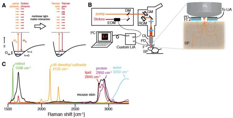
(A) Energy diagram of SRS. If the difference frequency of the excitation beams Δω=ωp-ωS matches a vibrational frequency in the sample at Ωvib, a molecule is excited from the vibrational ground state (ν=0) to a vibrational excited state (ν=1), passing through a virtual state (VS). This results in a photon in the pump field being annihilated (stimulated Raman loss) and a photon in the Stokes field being created (stimulated Raman gain) which can be probed as a contrast for microscopy. (B) Experimental setup for in vivo SRS microscopy. The Stokes beam is modulated with an electro-optic modulator (EOM), spatially overlapped with the pump beam with a dichroic mirror (DM) and aligned into a laser scanning microscope. The beams are focused by the objective lens (OL) and the common focal spot is scanned through the specimen (SP) by a galvo mirror (GM) and a resonant galvo mirror (RGM). The detected intensity of the backscattered pump beam is demodulated with a custom high speed lock-in amplifier (LIA) to provide the SRS signal to the computer (PC). The inset depicts the epi-detector assembly. The sample is excited by focusing light through a small hole in the center of the large-area epi-detector (PD). Scattering re-directs a significant portion of the forward-traveling light to illuminate the detector active area. The modulated Stokes beam is blocked by an optical filter (FI), and the transmitted pump beam is detected. (C) Raman spectra of chemical compounds imaged in this work. To image the architecture of skin, we make use of the OH-stretching vibration of water (3250 cm-1, blue), the CH3 stretching vibration, which primarily arises from protein (2950 cm-1, magenta, represented by soy protein extract), and the CH2 stretching vibration, which arises primarily from lipids (2845 cm-1, red, represented by oleic acid). Exogenous topically applied drugs may have unique vibrational signatures, such as the polyene stretching vibration of retinol (1596 cm-1, green), or may be labeled with deuterium and imaged using C-D stretching, in this case of d6-dimethyl sulfoxide (2125 cm-1, yellow).
First, previous SRS images required ~1 minute per frame, which is much too slow because living animals and humans inevitably move on the microscopic scale (movie S1), blurring the images. To achieve high speed imaging (Fig. 1B), we modulate the intensity of the Stokes beam at 20 MHz and use a home-built all-analog lock-in amplifier with a response time of ~100 ns (Fig. S2). The co-linear laser beams were tuned to match a vibrational frequency of interest (Fig. 1C) and raster-scanned across the sample by a resonant galvanometer mirror with a line rate of 8 kHz (100 ns per pixel at 512×512 pixels with up to 30 frames/second). While previous SRS microscopy was limited by the 100 μs response time of a commercial lock-in amplifier (SR844, Stanford Research Systems), our new system is three orders of magnitude faster.
Second, SRS microscopy involves measurement of the intensity loss of the transmitted pump beam, which is not feasible in thick, non-transparent samples (e.g. a human arm). Therefore, we must rely on back-scattering of the forward-going signal by tissue. This was previously collected by the excitation objective (14), which works for samples with extremely high scattering (18). However, in biological tissues, the epi-directed signal collected through the objective is too weak for high speed imaging:even with >60s integration time, the signal-to-noise obtained from tissue was poor (14).
To quantitatively understand the light collection in epi-SRS, we performed non-sequential ray tracing simulations (19), in which we simulate the propagation of a large number (~106) of rays emitted from the focal volume into a bulk medium with user-defined scattering parameters, which is used as a model for tissue (Fig. 2A). Scattering events along a ray’s trajectory are modeled probabilistically (20), and we measure the final distribution of the light after it is emitted from the simulated tissue volume. We find that, as expected, 40-45% of the light is backscattered in a thick tissue sample because scattering dominates over absorption in most tissues (21). Because of multiple-scattering, the diffuse cloud of back-scattered light has a radius of ~5 mm at the front aperture of the objective lens (Fig. 2B), largely independent of the excitation numerical aperture (Fig. 2C). A typical microscope objective has a front aperture radius of ~1-2 mm, so more than 90% of the backscattered light does not even enter the objective. We solve this problem by placing the photodetector directly in front of the objective lens, and exciting through a hole in the center of the detector (Fig. 1B). In this geometry, we experimentally found in mouse skin that we were able to collect ~28% of the laser light impinging onto the sample. Given the angular distribution of the back-scattered light (Fig. S3), a filter to block the modulated Stokes beam while transmitting the pump beam had to be specially designed (Fig. S4).
Fig. 2. Non-sequential ray-tracing simulations of collection efficiency with an annular detector.
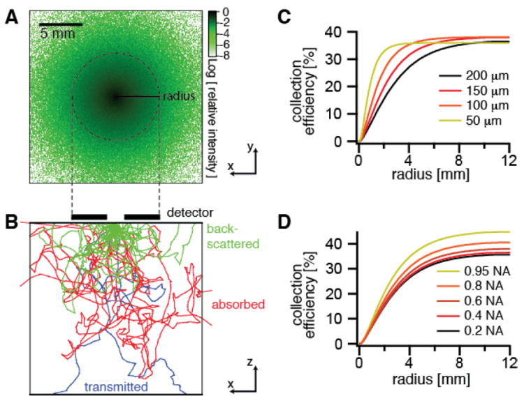
(A) Logarithmic plot of the distribution of the relative intensity of the backscattered light at the tissue surface from a focus at a depth of 100 μm into the tissue (scattering mean free path = 200 μm, anisotropy = 0.9) emitting in the forward direction with a 0.4 numerical aperture. (B) Depth profile of tissue showing sample ray trajectories colored according to the final outcome. Green traces are back-scattered to the tissue surface, red traces are scattered within the tissue until they are absorbed, and blue traces are transmitted through the 2 cm thickness of the sample. (C,D) Simulations of collection efficiency of back-scattered forward-traveling light versus detector radius for (C) different scattering mean free paths μS of the sample and (D) different numerical apertures (NA) of the excitation objective.
Using this system, we image skin in vivo in mice. Figure 3 shows single SRS video rate frames obtained using the CH2 stretching (primarily lipids, Fig. 3A,D), OH stretching (primarily water, Fig. 3B,E) and CH3 stretching (primarily protein, Fig. 3F,G) vibrations. The lipid distributions (movie S2) are as expected from previous work (14), but water can only be measured in vivo because the skin hydration changes in excised tissue. Imaging water is of particular interest in studying the transport properties of water-soluble drugs and their effect on the hydration of the skin barrier (22).
Fig. 3. SRS skin imaging in living mice.
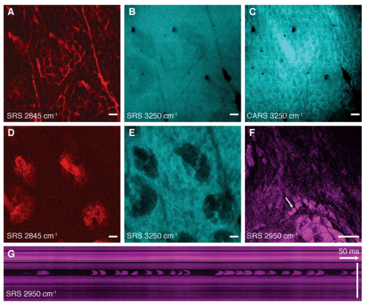
(A) SRS image of lipids of the stratum corneum shows intercellular spaces between hexagonal corneocytes and (B) SRS water image (3250 cm-1) of the same region shows a homogenous distribution of water. (C) A CARS water image acquired simultaneously with (B) shows artifacts from the non-resonant background of lipids. (D) SRS lipid and (E) water images of the viable epidermis show sebaceous glands with positive and negative contrast, respectively. (F) SRS images of the viable epidermis at the CH3 stretching vibration (2950 cm-1) mainly highlights proteins as well as residual lipid-rich structures. A capillary with individual red blood cells (arrow) is visible. The cells are imaged without motion blur due to video rate acquisition speed. (G) SRS in vivo flow cytometry. An x-t plot acquired by line-scanning across a capillary at the position of the arrow in (F). Individual red blood cells are captured on the fly. (A-E) are acquired in epi-direction, while (F) and (G) are acquired in transmission, all with 37 ms / frame acquisition speed and 512 × 512 pixel sampling. Scale: 25 μm.
Figure 3C highlights that CARS imaging of water is distorted by the nonresonant background, which introduces an image artifact: it shows positive contrast for the lipid-rich areas of the stratum corneum layer, which do not contain water. Thus the contrast in CARS is inverted compared to the real water distribution. This effect is not observed in SRS because it is free from this background (14). Signal averaging can further improve the signal-to-noise ratio if the sample remains still enough (Fig. S5).
The protein image (Fig. 3F, G and Fig. S6) shows red blood cells moving in a capillary of the viable epidermis (movie S3). By performing a line-scan over time we reconstructed a plot of the cells as they pass through the scan line (Fig. 3G), allowing for in vivo flow cytometry (23) based on intrinsic chemical contrast.
Figure 4 demonstrates the ability of SRS microscopy to follow the penetration of a small molecule drug (trans-retinol, which stimulates collagen synthesis) into mouse skin. Contrast using the CH3 and CH2 stretching highlights the morphology of the skin. By tuning in to the polyene stretch of retinol, we see that the drug has penetrated via the hair shaft into the sebaceous gland, one of three hypothesized penetration routes into skin (24, 25). Averaging the three-dimensional data (movie S4), we see the localization of retinol surrounding the hair and in the top of the sebaceous gland (Fig. 4L). In our previous work, performed using excised tissue, this pathway was not observed (14), indicating the importance of in vivo studies because the transport properties of small molecules can be affected by the skin temperature, moisture content and other factors.
Fig. 4. In vivo imaging of drug penetration of trans-retinol.
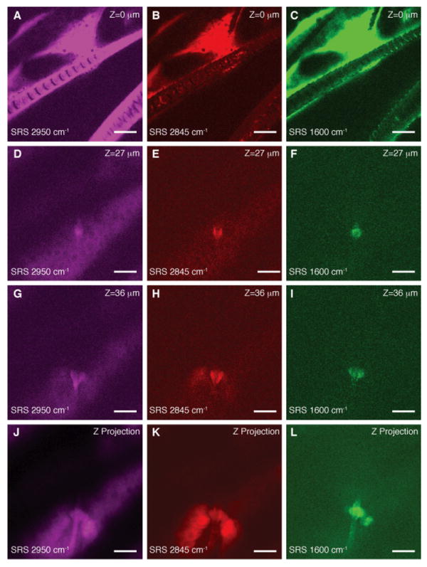
(A-C) SRS images of hair and stratum corneum in the ear of a living mouse. (D-F) Images of a hair shaft within the viable epidermis. (G-I) Images of a sebaceous gland within the viable epidermis. (J-L) Depth projection of three-dimensional image stacks of the viable epidermis. Images are acquired at the indicated Raman shifts. Contrast coming primarily from protein (2950 cm-1) and lipid (2845 cm-1) shows the morphology of the skin with all its structural elements and sub cellular resolution (see nuclei in D and K). Hairs are visible as solid structures in the protein image (D) and surrounded by oil secreted from the sebaceous glands in the lipid image (E). We are able to visualize with SRS that drug penetration of the topically applied trans-retinol (C) occurs along the hair shaft (F,I and L). Images are collected in transmission with 37 ms / frame acquisition speed and 512 × 512 pixel sampling. Scale: 25 μm.
Figure 5 shows in vivo SRS imaging of human skin. Cell layers of the viable epidermis can be seen when tuned in to the CH3 stretching band. High contrast is available for nuclei (Fig. 5A,B) and the varying nuclear size can be used to find the boundary between the viable epidermis and the stratum corneum. Figure 5C shows a hair disappearing down the hair shaft. In this case, deuterated DMSO, a penetration-enhancing small molecule, was applied to the skin. By tuning to the C-D stretching vibration at 2125 cm-1, contrast from DMSO appeared. It can again be seen that it accumulates in the area surrounding the hair, though it does not completely penetrate into the hair itself. Such mechanistic insight into the transport of small molecules can only be obtained from label-free chemical imaging.
Fig. 5. SRS skin imaging in living humans.
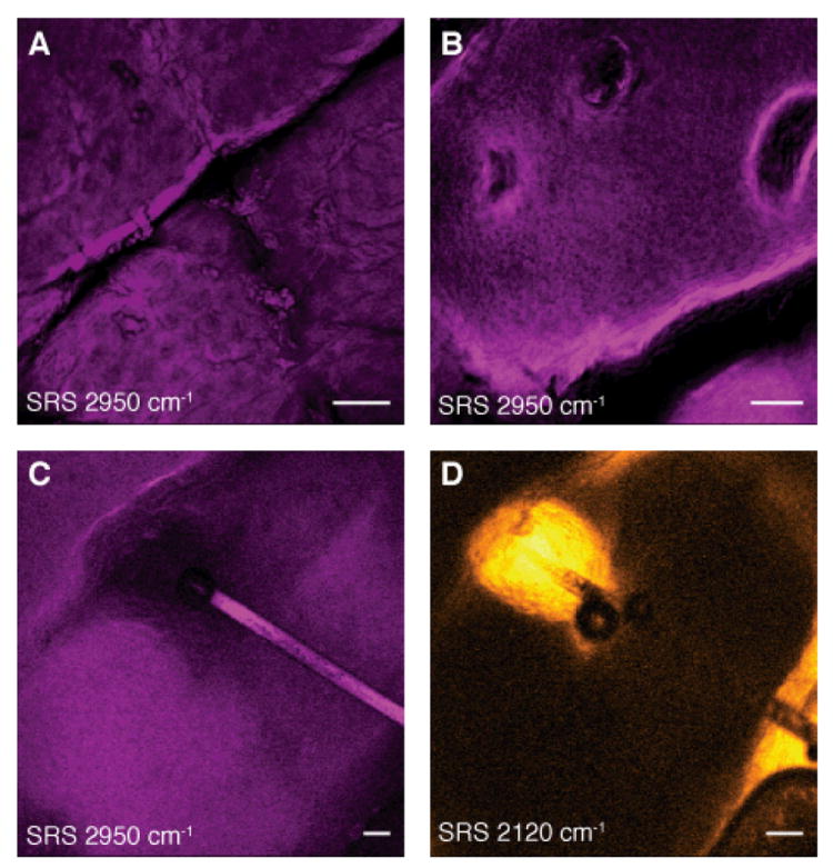
(A-C) SRS images of the stratum corneum and viable epidermis tuned into CH3 stretching vibration of proteins (2950cm-1) showing nuclei of variable size (A and B) as well as a hair (C). (D) SRS image of DMSO penetrating the skin at the same region as (C). We find that DMSO also accumulates in the hair shaft. We used deuterium labeling to create a unique vibration of d6-DMSO at 2120 cm-1 for specific imaging. Images are acquired in epi-direction on the forearm of a volunteer. Image acquisition time is 150 ms for (A) and (B) and 37 ms for (C) and (D), all with 512 × 512 pixel sampling. Scale: 50 μm.
By overcoming the challenges associated with performing high speed, epi-detected SRS microscopy, this powerful label-free imaging modality can now be applied to a broad range of problems in whole living organisms including small animals and humans. Label-free optical imaging is likely to play an increasingly important role in medical diagnostics in humans.
Supplementary Material
Acknowledgments
We thank J. MacArthur for advice on electronics, J. Reichman for the optical filter design, and K. Sherwood, W. Faustino and X. Zhang for helpful discussions. C.W.F. was supported by a Boehringer Ingelheim Fonds Ph.D. Fellowship. This work was supported by the Gates Foundation and an NIH T-R01 award to X.S.X.
Footnotes
Supporting material is available: Methods, Fig. S1-S6, Movies S1-S4
Competing financial interests. Patent applications based on this work have been filed by Harvard University.
Animal Research. Imaging of mice was performed in accordance with Harvard University Faculty of Arts and Sciences IACUC protocol number 29-01.
References
- 1.Masters BR, So PT, Gratton E. Biophys J. 1997;72:2405. doi: 10.1016/S0006-3495(97)78886-6. [DOI] [PMC free article] [PubMed] [Google Scholar]
- 2.Llewellyn ME, Barretto RPJ, Delp SL, Schnitzer MJ. Nature. 2008;454:784. doi: 10.1038/nature07104. [DOI] [PMC free article] [PubMed] [Google Scholar]
- 3.Levenson MD, Kano SS. Introduction to Nonlinear Laser Spectroscopy. Academic Press Inc.; 1988. [Google Scholar]
- 4.Zumbusch A, Holtom GR, Xie XS. Phys Rev Lett. 1999;82:4142. [Google Scholar]
- 5.Evans CL, Xie XS. Annu Rev Anal Chem. 2008;1:883. doi: 10.1146/annurev.anchem.1.031207.112754. [DOI] [PubMed] [Google Scholar]
- 6.Huff TB, Cheng JX. J Microsc. 2007 Feb;225:175. doi: 10.1111/j.1365-2818.2007.01729.x. [DOI] [PMC free article] [PubMed] [Google Scholar]
- 7.Hellerer T, et al. P Natl Acad Sci USA. 2007;104:14658. doi: 10.1073/pnas.0703594104. [DOI] [PMC free article] [PubMed] [Google Scholar]
- 8.Evans CL, et al. Proc Nat Acad Sci USA. 2005;102:16807. doi: 10.1073/pnas.0508282102. [DOI] [PMC free article] [PubMed] [Google Scholar]
- 9.Rinia HA, Bonn M, Müller M. J Phys Chem B. 2006;110:4472. doi: 10.1021/jp0564849. [DOI] [PubMed] [Google Scholar]
- 10.Ganikhanov F, Evans CL, Saar BG, Xie XS. Opt Lett. 2006;31:1872. doi: 10.1364/ol.31.001872. [DOI] [PubMed] [Google Scholar]
- 11.Li L, Wang H, Cheng J-X. Biophys J. 2005;89:3480. doi: 10.1529/biophysj.105.065607. [DOI] [PMC free article] [PubMed] [Google Scholar]
- 12.Cheng JX, Volkmer A, Xie XS. JOSA B. 2002;19:1363. [Google Scholar]
- 13.Ploetz E, Laimgruber S, Berner S, Zinth W, Gilch P. Applied Physics B: Lasers and Optics. 2007;87:389. [Google Scholar]
- 14.Freudiger CW, et al. Science. 2008;322:1857. doi: 10.1126/science.1165758. [DOI] [PMC free article] [PubMed] [Google Scholar]
- 15.Nandakumar P, Kovalev A, Volkmer A. New J Phys. 2009 Mar 25;11 [Google Scholar]
- 16.Ozeki Y, Dake F, Kajiyama S, Fukui K, Itoh K. Opt Exp. 2009 Mar 2;17:3651. doi: 10.1364/oe.17.003651. [DOI] [PubMed] [Google Scholar]
- 17.Saar BG, et al. Angew Chem Int Ed. 2010;49:5476. doi: 10.1002/anie.201000900. [DOI] [PubMed] [Google Scholar]
- 18.Slipchenko MN, et al. The Analyst. 2010 doi: 10.1039/c0an00252f. in press (available online) [DOI] [PubMed] [Google Scholar]
- 19.Zemax User’s Guide. Zemax Development Corp.; Bellevue, WA: 2010. [Google Scholar]
- 20.Jacques SL, Alter CA, Prahl SA. Lasers Life Sci. 1987;1:309. [Google Scholar]
- 21.Cheong WF, Prahl SA, Welch AJ. IEEE J Quant Elec. 1990;26:2166. [Google Scholar]
- 22.Rawlings AV, Harding CR. Dermatologic Therapy. 2004;17:43. doi: 10.1111/j.1396-0296.2004.04s1005.x. [DOI] [PubMed] [Google Scholar]
- 23.Sipkins DA, et al. Nature. 2005;435:969. doi: 10.1038/nature03703. [DOI] [PMC free article] [PubMed] [Google Scholar]
- 24.Prausnitz MR, Mitragotri S, Langer R. Nature Rev Drug Disc. 2004;3:115. doi: 10.1038/nrd1304. [DOI] [PubMed] [Google Scholar]
- 25.Lademann J, et al. Skin Pharmacology and Physiology. 2008;21:150. doi: 10.1159/000131079. [DOI] [PubMed] [Google Scholar]
Associated Data
This section collects any data citations, data availability statements, or supplementary materials included in this article.