

Nanotechnology aims to organize matter with the highest possible accuracy and control. Such control will lead to nanoelectronics, nanorobotics, programmable chemical synthesis, scaffolded crystals, and nanoscale systems responsive to their environments. Structural DNA nanotechnology1 is one of the most powerful routes to this goal. It combines robust branched DNA species with the control of affinity and structure2 inherent in the programmability of sticky ends. The successes of structural DNA nanotechnology include the formation of objects,3 2D crystals,4 3D crystals,5 nanomechanical devices,6 and various combinations of these species (e.g., ref. 7). DNA origami8 is arguably the most effective way of producing a large addressable area on a 2D DNA surface. This method entails the combination of a long single strand (typically M13 single-stranded form, 7249 nucleotides) with about ~250 staple strands to define its shape and patterning. With a pixilation estimated at about 6 nm,8 it is possible to build patterns with about 100 addressable points within a definable shape in an area of about 10,000 nm2. Many investigators have sought unsuccessfully to increase the useful size of 2D origami units by forming crystals of individual origami tiles.0 Here, we report the 2D crystallization of origami tiles to yield a 2D array with dimensions 2–3 microns on an edge. This size is likely to be large enough to connect bottom-up methods of patterning with top-down approaches.
Crystalline arrays are a convenient way to propagate patterns and other distributions of matter, so that multiple copies can self-organize into large periodic or aperiodic systems. DNA is a particularly powerful system for this type of organization, because it is possible to flank structural motifs with sticky ends, so that Watson-Crick complementary interactions can be programmed to establish the intermolecular contacts.1 DNA double crossover (DX) motifs are examples of small tiles (~4 nm × ~16 nm) that have been programmed to produce 2D crystals;4 often these tiles contain pattern-forming features when more than a single tile constitutes the crystallographic repeat. These motifs contain two parallel double helices, held together by crossovers; the second dimension derives from connecting one helix of a given tile to the other helix of an adjacent tile, as shown in Figure 1a. In addition to the periodic pattern shown there, this form of intermolecular organization has been used to produce aperiodic 2D arrays.9,10 It is clear that one would like to be able to make 2D arrays of DNA origami tiles, at least on the micron scale. This is a particularly appealing goal, since DNA origami tiles are basically large versions of the DX motif, typically containing many parallel double helices, rather than two. However, this approach has proved to be unsuccessful. A sample failure of 2D origami tile self-assembly is shown in Figure 1b, where a rectangular origami tile with a cavity at its center has been self-assembled. There are rarely more than a half-dozen tiles in the second dimension, so the result is scarcely better than a 1D array.
Figure 1.

Forming 2D Arrays from Molecules with Parallel Double Helical Domains. (a) A double crossover (DX) molecule. The schematic shows two molecules, a red one, A, and a blue one, B*; the B* molecule is a DX+J molecule, containing an extra double helical domain (the black filled circle) perpendicular to the plane of the helix axes. The sticky ends are represented as complementary geometrical features. Note that the key to producing a second direction with the DX tiles is the binding of the ‘top’ domain of the red tile to the ‘bottom’ domain of the blue tile. This system readily forms a 2D crystalline array wherein the extra domain produces a series of stripes separated by the sum of the lengths of the two double helices; the stripes are typically separated by 32 nm. (b) An attempt to form a 2D array from rectangular DNA origami tiles using the strategy of (a). The tiles all have a small cavity at their centers. The helix axes are parallel to the long axes of the origami tiles. No more than about six tiles (equivalent to, say, the red tiles of (a)) repeat in the long direction, and no more than about six tiles are joined horizontally when this strategy is employed.
The key to solving this problem lies in recognizing that all the helix axes in Figure 1b lie parallel to the direction in which the tiles actually cohere. Thus, a possible alternative method to make a 2D origami array is to use an origami tile whose helix axes propagate in two independent directions. A schematic of two such tiles (A and B) is shown in Figure 2a. The use of two independent tiles enables AFM analysis of individual tiles without inter-tile cohesion. The strand structures of these molecules are shown in Figure S1. An AFM image of this tile is shown in Figure 2b, with dimensions of 100 nm × 100 nm. The key feature of this system is that there are two domains to the origami tile, one in a plane above the other. The two domains clearly have orthogonal directions of propagation, thereby solving the problem that arose when we tried to use the DX-tile approach with DNA origami. Note a small vacant horizontal box-like feature on the bottom plane of the A tile; this feature is vertical in the B tile. In both cases, it leads to a visible bifurcation in the central part of the origami tile. This feature is emphasized in the lower left inset in Figure 2b. Height analysis of the tile is shown in Figure S2.
Figure 2.
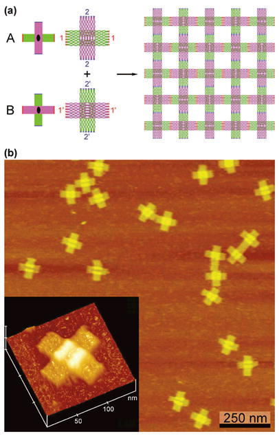
Origami Tiles with Orthogonal Directions of Propagation. (a) Schematics of the Tiles. Two different tiles, A and B, are shown. At left are simplified drawings showing the orthogonal nature of the tile propagation directions, their twofold axes, with color-coded sticky ends, red and blue. In a more realistic representation to the right the tiles are shown with their sticky end sets labeled with the numbers 1 and 2, as well as their complements 1′ and 2′; these images were generated by the program NanoEngineer (www.nanoengineer-1.net). The purple rectangular domain lies above the green rectangular domain in both tiles. This leads to the woven pattern shown on the right when the two tiles are combined. Note that there is a cavity in the green domain which is drawn horizontally in the A tile and vertically in the B tile. Except for the sticky ends, the two tiles are the same. (b) Atomic Force Micrographs of the A tile. Individual tiles are seen to form the cross-like structures shown in (a). The inset at the lower left emphasizes the overlap of the two domains that flanks the cavity. The cavity is visible and flanked clearly by the white region, which represents a thicker system (see Supporting Information).
Yan and his colleagues11 showed that small cross-like DNA motifs may have a certain amount of curvature, so defeating this problem to produce flat 2D arrays is to employ a corrugation strategy, which rotates the orientations of alternate members of the array within the plane, thus cancelling out errors. We found this type of tactic necessary as well, to avoid tube formation; an alternating array is shown on the right of Figure 2a. However, our corrugation strategy differs from that used by Yan et al.: Owing to the two layers of the origami tile having opposite orientations relative to the tile plane, we alternate the origami tiles with the same tiles rotated by 90°, thereby bonding the top half of one tile to the bottom half of the next; this approach achieves the same result in this case, indicating that the two domains distort from planarity in opposite relative directions (e.g., one curving up and one curving down). Thus, the design entails an alternating structure that leads to what looks like a braided origami pattern (Figure 2a), wherein the top layer of one tile bonds with the bottom layer of the adjacent tile. We have implemented this approach using two different tiles (A and B), to build a 2D crystalline array of origami tiles. An AFM image of such an array is shown in Figure 3a. It is clear that the origami tiles form a regular rectilinear array that looks like a latticework roughly 3 microns by 2 microns in extent; the edges are seen to contain step-like features. Figure 3b is a zoomed image of a 2D array, showing the quality of the crystalline arrangement. Note the alternating orientation of the bifurcation feature.
Figure 3.
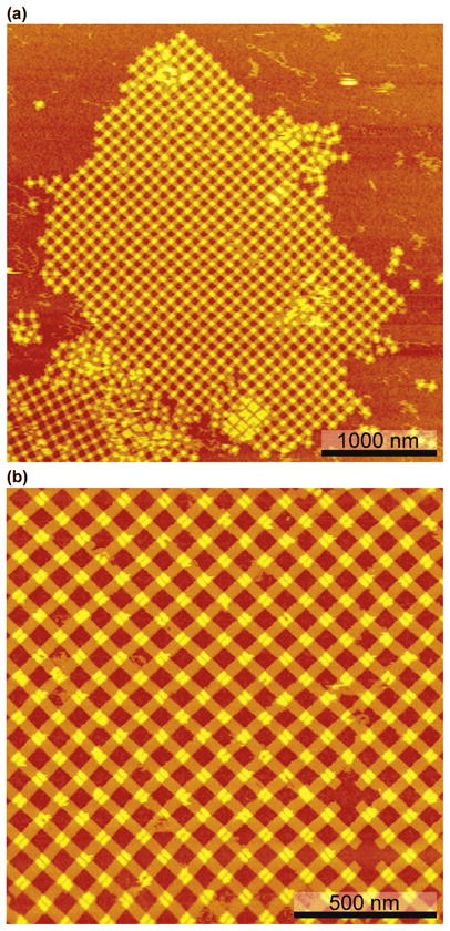
Two-Dimensional Origami Arrays. (a) A View of an Array with Dimensions ~ 2 Microns × 3 Microns. This is among the cleanest of the arrays that we have observed, but certainly not the largest, whose dimensions can reach nearly 10 microns (Figure S3). The edges of this array are often straight, but they do demonstrate the step-like features typical of a growing lattice. (b) A Zoom of (a). This is an array of high quality. Note that the cavity-flanking features alternate as suggested by the images shown in (b).
After the individual origami tiles are formed, they are mixed together. The annealing temperature in this annealing step is crucial for the formation of the 2D DNA origami array. Since the tiles used to set up DNA origami 2D arrays contain multiple sticky ends on each connection site, the annealing temperature is different from that of normal DNA tiles that contain only one or two sticky ends on each connection site. Therefore, the temperature must be carefully optimized, to make sure it is neither too high nor too low: If the temperature is too high, the origami tiles that are formed in the first annealing step will be damaged and cannot associate with each other to form 2D arrays. On the other hand, if the temperature is too low, the result is that a great number of crystal nuclei are created and those tiny pieces of arrays randomly aggregate with each other, leading to the formation of no large 2D crystals. Examples of annealing origami tiles with each other at 45, 53, 60 and 65 °C are shown in Figure 4; only annealing at 53 °C was successful.
Figure 4.
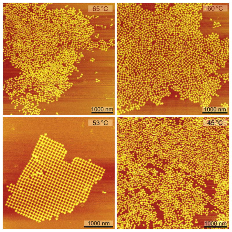
Temperature Optimization of 2D Array Formation. It is evident that only annealing the tiles in a protocol starting at 53 °C was successful. If the temperature is too high, the tiles that are formed in the first annealing step will be damaged and cannot associate with each other to form 2D arrays. If the temperature is too low, the result is that a great number of crystal nuclei are created and those tiny pieces of arrays randomly aggregate with each other, resulting in the formation of no large 2D crystals.
Rothemund8 has shown a map of the Western Hemisphere displayed an origami based on M13. This image shows clearly about 85 patterned pixels, occupying about 40% of the visible area. Periodic repeats containing 8 DNA small tile units have already been constructed.7 Algorithmic self-assemblies9,10 can lead to even greater diversity and pattern complexity. The ability to form 2D crystalline arrays of DNA origami tiles expands greatly the current capability of generating bottom-up pattern complexity. In addition, without increasing the size of the scaffold strands, the success reported here suggests that it will be possible to make oligo-origami tiles in two dimensions, so that applications like captures12 and assembly lines13 are not frustrated by the limited sizes of single M13-based origami tiles. This work brings us to the point where bottom-up organization of matter can meet the limits of the top-down organization of matter.14 Thus, complexity generated by bottom-up construction might well be replicable on a large scale by routine methods used industrially.
Experimental Section
Design of the Origami Tile
A circular single-stranded M13mp18 DNA genome (7249 nucleotides (nt) in length) is held together by 201 short staple strands to form the DNA origami tiles. These origami tiles contain two identically-sized rectangular domains (a green one and a purple one (Figure 2), 288 nt long and 12 helices wide) that sit at 90° angles on top of each another; consequently, the tile has an aspect ratio of 1:1 (~95 nm × 95 nm). The two rectangular domains have opposite orientations relative to the tile plane (one domain is face-up and the other is face-down), and they are connected to each other by the M13 scaffold strand; in addition, they are connected by 18 joint staple strands in the middle of the tile to enforce a 90° angle between the two domains. The M13 scaffold strand is designed to contain two-nucleotide single-stranded spacers to maintain flexibility at joints between the two domains. We also inserted one or two thymidine spacers into the joint staple strands for the same purpose.
To assemble the origami tiles into 2D arrays, the basic tile was modified by adding sticky ends to each branch of the tile to form two complementary tiles (A and B). Thus, these two tiles have an axis of two-fold rotational symmetry perpendicular to the tile plane. Each domain of tile contains one set of sticky ends, and each set is composed of eight different 5-nt sticky ends that were designed using the program SEQUIN.15 The sticky-ended associations are indicated by different colors and complementary numbers in Figure 2a.
Formation and Assembly of the Tiles
Individual tiles were assembled by thermal annealing of the mixture of the M13 scaffold DNA and all staple strands including the purified sticky-end strands in 1× TAE-Mg2+ buffer (pH 8.0) from 90 °C to 16 °C over the course of 13 h in a thermocycling device. The origami tile forms as designed with high yield and a highly homogenous shape. The surface plot of one origami tile (Figure 2b, inset) clearly shows that this tile is a double layer structure with one domain laying at 90° to the other. The AFM height profile of the origami tiles (Figure S2) reveals that the average size of the tiles is around 100 nm × 100 nm, and the height of the central part of the tile is roughly twice of the height of the surrounding part of the tile, which is in good agreement with the design.
Two-Dimensional Array Formation
The formation of the DNA origami 2D array was carried out through a two-step annealing process. In the first step, each individual tile was separately formed by mixing M13 scaffold strands with their component staple strands including purified sticky-end strands and annealing from 90 °C to 16 °C in a thermocycling device (Eppendorf) over the course of 13 h. In the second step, the two tiles were mixed together in stoichiometric quantities and cooled slowly from 53 °C to 20 °C in a chilling/heating incubator (ECHOthermTM IN35) over 178.5 h (see supporting information).
Supplementary Material
Footnotes
This research has been supported by the following grants to NCS: GM-29544 from the National Institute of General Medical Sciences, CTS-0608889 and CCF-0726378 from the National Science Foundation, 48681-EL and W911NF-07-1-0439 from the Army Research Office, N000140910181 and N000140911118 from the Office of Naval Research and a grant from the W.M. Keck Foundation.
Supporting information for this article is available on the WWW under http://www.angewandte.org or from the author.
References
- 0.Li Z, Liu M, Wang L, Nangreave J, Yan H, Liu Y. J Am Chem Soc. 2010;132:13545–13552. doi: 10.1021/ja106292x. [DOI] [PMC free article] [PubMed] [Google Scholar]
- 1.Seeman NC. J Theor Biol. 1982;99:237–247. doi: 10.1016/0022-5193(82)90002-9. [DOI] [PubMed] [Google Scholar]
- 2.Qiu H, Dewan JC, Seeman NC. J Mol Biol. 1997;267:881–898. doi: 10.1006/jmbi.1997.0918. [DOI] [PubMed] [Google Scholar]
- 3.Chen J, Seeman NC. Nature. 1991;350:631–633. doi: 10.1038/350631a0. [DOI] [PubMed] [Google Scholar]
- 4.Winfree E, Liu F, Wenzler LA, Seeman NC. Nature. 1998;394:539–544. doi: 10.1038/28998. [DOI] [PubMed] [Google Scholar]
- 5.Zheng J, Birktoft JJ, Chen Y, Wang T, Sha R, Constantinou PE, Ginell SL, Mao C, Seeman NC. Nature. 2009;461:74–77. doi: 10.1038/nature08274. [DOI] [PMC free article] [PubMed] [Google Scholar]
- 6.Yan H, Zhang X, Shen Z, Seeman NC. Nature. 2002;415:62–65. doi: 10.1038/415062a. [DOI] [PubMed] [Google Scholar]
- 7.Ding B, Seeman NC. Science. 2006;314:1583–1585. doi: 10.1126/science.1131372. [DOI] [PMC free article] [PubMed] [Google Scholar]
- 8.Rothemund PWK. Nature. 2006;440:297–302. doi: 10.1038/nature04586. [DOI] [PubMed] [Google Scholar]
- 9.Rothemund PWK, Papadakis N, Winfree E. PLoS Biol. 2004;2:2041–2053. doi: 10.1371/journal.pbio.0020424. [DOI] [PMC free article] [PubMed] [Google Scholar]
- 10.Fujibayashi K, Hariadi R, Park SH, Winfree E, Murata S. NanoLett. 2008;8:1791–1797. doi: 10.1021/nl0722830. [DOI] [PubMed] [Google Scholar]
- 11.Yan H, Park SH, Finklestein G, Reif JH, LaBean TH. Science. 2003;301:1882–1884. doi: 10.1126/science.1089389. [DOI] [PubMed] [Google Scholar]
- 12.Gu H, Chao J, Xiao SJ, Seeman NC. Nature Nanotech. 2009;4:245–249. doi: 10.1038/nnano.2009.5. [DOI] [PMC free article] [PubMed] [Google Scholar]
- 13.Gu H, Chao J, Xiao SJ, Seeman NC. Nature. 2010;465:202–205. doi: 10.1038/nature09026. [DOI] [PMC free article] [PubMed] [Google Scholar]
- 14.Kershner RJ, Bozano LD, Micheel CM, Hung AH, Fornof AR, Cha JN, Rettner CT, Bersani M, Frommer J, Rothemund PWK, Walraff GM. Nature Nanotech. 2009;4:557–561. doi: 10.1038/nnano.2009.220. [DOI] [PubMed] [Google Scholar]
- 15.Seeman NC. J Biomol Struct Dyns. 1990;8:573–581. doi: 10.1080/07391102.1990.10507829. [DOI] [PubMed] [Google Scholar]
Associated Data
This section collects any data citations, data availability statements, or supplementary materials included in this article.