

Abstract
Purpose
This study aimed to improve the effectiveness of orthotic treatment for the patients with AIS using the three-dimensional clinical ultrasound (3D CUS) method in which the optimal location of pressure pad of spinal orthosis was determined with the assistance of ultrasound image analysis.
Methods
By means of 3D CUS method, the spinous process angle (SPA) could be traced and used as a clinical parameter to estimate the Cobb’s angle in order to determine the location of pressure pad. Twenty-one patients (test group) and 22 patients (control group) were recruited to the ultrasound-assisted fitting method and the conventional fitting method, respectively. All the measurements were done by a blinded observer.
Results
The intra-rater reliability of using 3D CUS to measure SPA was found >0.9 [ICC (3,3) = 0.91, p < 0.05]. In the test group, 13 out of 21 patients were required to adjust the location of pressure pad in order to achieve the largest curvature correction. The mean immediate in-brace corrections (Cobb’s angle measured from radiographs) of the test group (mean thoracic curve correction: 10.3°, mean lumbar curve correction: 10.1°) were found significantly higher (p < 0.005) than that of the control group (mean thoracic curve correction: 4.6°, mean lumbar curve correction: 6.0°). The results showed that the ultrasound-assisted fitting method of spinal orthosis was effective and beneficial to 62 % of the patients in this study.
Conclusions
The 3D CUS could be considered as an effective, non-invasive and fast assessment method to scoliosis, especially in enhancing the effectiveness of orthotic treatment and its applications could also be further extended to other spinal deformities.
Keywords: Three-dimensional clinical ultrasound, Adolescent idiopathic scoliosis, Spinous process angle, Fitting of spinal orthosis
Introduction
Adolescent idiopathic scoliosis (AIS) is described as structural deformity with lateral curvature and vertebral rotation of the spine that happens in adolescence with unknown causes [6, 7, 21, 22, 26]. The most commonly used parameter to measure scoliotic curvature is Cobb’s angle. Spinous process angle (SPA), which is another parameter proposed to assess scoliotic curvature, is described as the accumulating angle formed by every two lines joining three neighbouring spinous processes of a scoliotic spine [13]. Some corresponding studies [16, 17] were conducted and high correlation between the Cobb’s angle and SPA was obtained from both the pre-brace and in-brace stages.
In routine clinical practice, the blueprint of orthotic treatment prescribed to patients with AIS is mainly based on the patient’s Cobb’s angle, vertebral rotation and curve pattern. The Cobb’s angle measured from the radiographs which are usually obtained at the pre-brace stage and regular clinical follow-up with a 4-month interval. However, no radiograph is usually taken in the fitting process of spinal orthosis in consideration of radiation exposure. Although radiography is a standard way to diagnose and evaluate curve progression, over a lifetime of having radiographs, a scoliosis patient can be cumulatively exposed to high doses of ionizing radiation [20]. In particular, radiography exposes sensitive breast tissues to ionizing radiation. Females comprise about 80 % of cases followed for scoliosis. The breast cancer rate has been reported higher in females who have been followed for scoliosis [14, 19]. In the conventional fitting method of spinal orthosis, trunk listing is generally used as an indicator to check whether the orthosis is alleviating or worsening the deformity in the fitting process. However, there is no evidence for a direct relationship between the trunk listing and the spinal curvature. Moreover, to what extent the deformities can be controlled during the orthosis fitting is far from known with the existing arrangements and practice.
Many researchers demonstrated the possibility of using ultrasound to detect the spinous processes [2, 9, 15, 18]. Suzuki et al. [23] used ultrasound to figure out the spinous processes and the laminae so as to assess the axial spinal rotation. Harrison et al. [11] diagnosed abnormal spinal curvature in the fetus with the use of ultrasound. Furness et al. [9] identified lumbar intervertebral level with ultrasound imaging and found that the correct identification was up to 71 % of cases. Burwell et al. [2] evaluated a new real-time ultrasound to measure the differences between axial spinal and rib rotation at the apex of the spine curvature. Lam et al. [15] established a normal ultrasound assessment of lumbosacral spine in children and concluded that ultrasound is a useful tool for diagnosis of suspected tethering of the spinal cord. McLeod et al. [18] studied the effectiveness of ultrasonography to facilitate the insertion of epidural catheters in scoliosis patients.
To determine the optimum location of pressure pad is not easy in the fitting process of spinal orthosis, because the radiograph taken at the pre-brace stage could not provide real-time information of the spinal curvature and the 3D deformities change once pressure pad is applied. With the advancement of clinical ultrasound technology, tracing spinous processes along a scoliotic spine becomes possible, which means SPA can be obtained from ultrasound images. Since the outcome of orthotic intervention for AIS is considered to be associated with accurate orthosis fitting and patient’s compliance to treatment, this study pursued the possibility of applying 3D CUS in the fitting process of spinal orthosis to patients with AIS. The accuracy of pressure pad location in the spinal orthosis can help to improve the effectiveness of orthotic treatment. Furthermore, it is generally observed that bracing may cause a reduction of thoracic kyphosis or even leading to thoracic hypo-kyphosis. Using 3D CUS as a fast and non-invasive assessment tool, this possible adverse effect could be closely monitored during the fitting of spinal orthosis.
It is hypothesized that 3D CUS is feasible to improve the treatment effectiveness of spinal orthosis via monitoring the curvature changes during the fitting process, even useful in prevention of hypo-kyphosis by improper fitting of spinal orthosis.
Methods
Patients
The patient selection criteria were as follows: (1) female patients with AIS; (2) Cobb’s angle: 20°–40°; (3) curve pattern: right thoracic (RT)/right thoracic and left lumbar (RTLL); (4) age: 9–14; (5) Risser’s sign: ≤2; (6) newly prescribed with spinal orthosis.
Forty-three patients were selected from the same scoliosis clinic and treated by the same Orthotist who had more than 20 years of experience in fitting of spinal orthosis. Twenty-one patients (test group) were recruited for the ultrasound-assisted fitting method and 22 patients (control group) underwent the conventional fitting method. The patients of the test group were all new cases from 2009 to 2010, while the patients of the control group were selected retrospectively from 2006 to 2009. All the measurements were done by a blinded rater.
Equipment
All ultrasound examinations were performed with an Esaote Technos MPX ultrasound unit (Esaote China Ltd., China) with a 7.5 MHz linear transducer, and in conjunction with an add-on 3D tracking system (Tom Tec 3-D Sono-Scan Pro, Germany). A silicon sleeve was purposefully designed and attached to the ultrasound probe to ensure a good surface contact between the patients back and ultrasound probe.
Clinical procedure
The clinical assessment, measurement, design and fabrication of spinal orthosis (using CAD/CAM method) were the same for the test group and the control group, and the only difference was the orthosis fitting procedure. The pre-brace posterio-anterior (PA) standing radiographs were routinely taken and used as references by the experienced Orthotist to design a blueprint for orthotic intervention. The patients were instructed to wear the orthosis 23 h a day for 2 weeks. After the 2-week adaptation period, the patients would return for further orthosis adjustments if necessary, and then they were referred to take in-brace PA standing radiograph for assessing the effectiveness of orthotic treatment.
In the control group, the Orthotist would use the conventional fitting method in which strategic adjustments are made, such as changing the location of the pressure pad or strap tension aiming to obtain the optimum improvement of the deformity through his own clinical experience and professional judgement.
In the test group, the patients were first scanned by 3D CUS in the standing position to obtain the spinous process images for estimation of the pre-brace SPA. Then they were fitted with spinal orthoses, and ultrasound imaging was performed at the posterior opening of the orthosis for tracing the spinal processes of the scoliotic spine. It was planned to alter the location of the pressure pad that would expect to render different biomechanical effects on the scoliotic spine. The experienced Orthotist started with his prescribed pad location (referring to the pre-brace radiograph) and strap tension (by experience). The Orthotist then made strategic adjustments, changing the location of the pressure pad (five positions: prescribed position; 1 and 2 cm above and below the prescribed position), so as to seek the optimum improvement of the SPA (best correction among the 5 pad locations). Once the lowest Cobb’s angle (estimated from the SPA via 3D US images) was obtained after the deliberate changes, the optimum pad location was confirmed and recorded. The resting procedures were same as that of the control group.
Application of 3D CUS
Before data acquisition, a position sensor was fixed onto the transducer and an electromagnetic field transmitter was placed on a wooden scanning stool. The region of interest was scanned through a single sweep, the reconstructed 3D images were reviewed, and the spinous processes were identified in the images.
Pre-brace scanning
In the pre-brace stage, the patient was instructed in standing position with feet at shoulder width and eyes looking at a horizontal steadfast object (set by a tripod). With the 3D CUS system activated, the region of scoliotic spine was scanned through a single sweep and three successful trials of data were captured (Fig. 1). One trial of a single sweep for acquiring the ultrasound images required about 40 s.
Fig. 1.
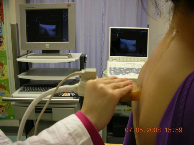
Pre-brace ultrasound scanning procedure
During the scanning, each slice of the images showed the transverse plane of the vertebra. After a complete scan, the 3D reconstructed ultrasound images of the whole spine were shown and analyzed with the Tom Tec system (Fig. 2a). The spinous process and laminae present as bright white lines in the transverse plane, curve lines in the sagittal plane and white dots in the coronal plane. The transverse plane of a vertebra dummy is shown in Fig. 2b and the image of transverse level of the most prominent region of the spinous process captured from the ultrasound system is shown in Fig. 2c. There is a bright reflection (green circles) at the tip of the spinous process in those images. In the same images, the reflection on the origin of the laminae can be observed (red circles). The reflections are the major indicators for confirming the identification of the spinous processes and laminae with the 3D CUS. After identifying all the spinous processes, a purpose-design software named spinous process angle calculator (SPAC) was used, in which lines were drawn through the tips of spinous processes; the angles between the lines were accumulated, and the sum angle was the SPA of the measured curve. One trial of identifying all spinous processes (from T1 to T12 and from L1 to L5) along the scoliotic spine required 4 min.
Fig. 2.

a 3D CUS reconstructed images of a spine by the Tom Tec System, b vertebral phantom, c transverse ultrasound image of vertebral phantom
In-brace scanning
In the current study, the location of pressure pad (Fig. 3) and the tightness of straps were firstly prescribed and marked by the experienced Orthotist according to the physical assessment and the pre-brace radiograph. The width of the posterior opening of spinal orthosis was set to 6.5 cm to ensure the ultrasound probe could get through the opening during 3D CUS scanning (the width of ultrasound probe is 6.2 cm). The width of the posterior opening was also used as the indicator to check the tightness of straps. The 3D CUS was then applied to assess the optimal location of the pressure pad. Before unfastening the straps of the spinal orthosis, a fast-grip setting was used to ensure the same orthosis tightness—using the width of the posterior opening as reference. After unfastening all the straps and exposing the posterior opening of the orthosis, the region of scoliotic spine was scanned through a single sweep (Fig. 4). The location of the pressure pad was adjusted and three trials of ultrasound scanning were conducted for each location of pressure pad.
Fig. 3.

a Five locations for pressure pad ([1]: dark circle, +2 cm; [2]: blue circle, +1 cm; [3]: red circle, original location; [4]: green circle, −1 cm; [5]: white circle, −2 cm). b Lateral view of the spinal orthosis
Fig. 4.

In-brace ultrasound scanning
The image analysis was similar to that of the pre-brace stage and the scoliotic angles in the coronal plane and kyphosis/lordosis angles in the sagittal plane were calculated. The SPA of the coronal plane was then used to assess curve correction in the orthotic treatment and the location of pressure pad was confirmed accordingly.
Measurements of SPA (coronal and sagittal planes)
The reconstructed images of the scoliotic spine in the coronal and sagittal planes processed from the 3D CUS were sent to the SPAC to compute the SPA in the coronal plane (Fig. 5) and in the sagittal plane (Fig. 6).
Fig. 5.

Spinous process angle calculator for measurements of SPA
Fig. 6.

Spinous process angle calculator for measurements of kyphosis and lordosis (sagittal plane)
With all the 3D ultrasound images analyzed, the SPAs assessed under the five designated locations of pressure pad were compared. The location of pressure pad that offered optimal immediate curve correction was considered as the best location among the five tested locations (Fig. 3). Similar method for confirming the optimal pressure pad location was applied onto all the 21 recruited patients of the test group to help improve the effectiveness of orthosis fitting. In this study, the patients of both the control group and the test group were assumed to have similar compliance to the prescribed treatment. A regular clinical follow-up was arranged after having orthotic treatment for 4 weeks and in-brace radiograph was taken for assessing the effectiveness of spinal orthosis.
Data analyses
The data were analyzed using the Statistical Package for Social Sciences (SPSS Statistics 17.0, Inc., USA). The confidence interval was set at 95 % (p < 0.05). The paired Student’s t tests were applied to compare the mean differences for the Cobb’s angle (coronal plane) between the pre-brace stage and the immediate in-brace stage for the control group as well as the test group. In addition, the independent samples t tests were applied to compare the mean differences for curvature correction with reference to the control group and test group both at the pre-brace stage and immediate in-brace stage as well as to compare the SPA (sagittal plane, from ultrasound images) of the pre-brace stage and that of the in-brace stage (with pressure pad at each location, respectively). The one-way repeated measures ANOVA was applied to compare the mean difference for the SPA (sagittal plane, from ultrasound images) among the five different pressure pad locations.
Results
Assessments of scoliotic spine (coronal plane and sagittal plane)
In the coronal plane, the mean SPAs were 21.6° and 15.9° at the pre-brace stage and the in-brace stage, respectively (with pressure pad at optimal location). The intra-rater reliability [ICC (3,3)] for using ultrasound to measure SPA was >0.9 (p < 0.05).
From the previous correlation study [16, 17], two formulas were derived for converting SPA to Cobb’s angle, which are y = 1.2963x−0.371 (r = 0.80, p < 0.05) for the pre-brace stage and y = 1.1588x + 0.5249 (r = 0.87, p < 0.05) for the in-brace stage (y = SPA, x = Cobb’s angle). Applying these formulas, Cobb’s angle could be estimated from the SPA measured by 3D CUS. Furthermore, the correlation between the Cobb’s angle estimated from SPA via 3D CUS and the Cobb’s angle measured from radiograph was found significant in both the pre-brace stage (r = 0.81, p < 0.05) and the in-brace stage (r = 0.89, p < 0.05).
The effect of spinal orthosis on the scoliotic spine in the sagittal plane (thoracic kyphosis and lumbar lordosis) was investigated under different locations of pressure pad using 3D CUS. According to the data analyses, the mean thoracic kyphosis and lumbar lordosis in the pre-brace stage were 39.5° and 42.0°, respectively. The mean reductions of thoracic kyphosis were 9.6°, 9.5°, 10.0°, 10.3°, and 9.8° with the pressure pad at the five designated locations, respectively (Table 1). The mean reductions of lumbar lordosis were 10.3°, 9.9°, 11.6°, 12.5°, and 11.7° with the pressure pad at the five designated locations, respectively (Table 1).
Table 1.
Mean SPA of kyphosis and lordosis (sagittal plane)
| Curve type | Mean SPA of pre-brace | Mean SPA of in-brace | ||||
|---|---|---|---|---|---|---|
| Position 1 (+2 cm) | Position 2 (+1 cm) | Position 3 (original) | Position 4 (−1 cm) | Position 5 (−2 cm) | ||
| Thoracic kyphosis (n = 21) | 39.5 | 29.5° | 30.0° | 29.9° | 29.6° | 30.1° |
| Lumbar lordosis (n = 21) | 42.0 | 30.3° | 32.1° | 31.6° | 29.7° | 30.5° |
The independent samples t tests for the pre-brace stage and the in-brace stage showed that both thoracic kyphosis and lumbar lordosis were significantly decreased by spinal orthosis at all the five designated locations of pressure pad. The one-way repeated measures ANOVA for the in-brace stage indicated that no significant difference was found among different locations for pressure pad.
Effectiveness of 3D CUS assisted fitting method on scoliotic spine
In the test group, 13 out of 21 patients were required to adjust the location of pressure pad. This indicated that ultrasound assisted in the fitting method of spinal orthosis was effective and helpful to 61.9 % of the patients in this study.
The software named Photoshop (Adobe Photoshop CS2 version, Adobe Systems Inc., USA) was used to improve the image quality of the radiographs. Cobb’s angle was measured by two observers (the first author and a blinded observer). The intra-rater [ICC(3,3)] and inter-rater [ICC(2,3)] measurement reliability of the Cobb’s angle from radiographs were found 0.99 and 0.96, respectively (p < 0.01). The pre-brace Cobb’s angle of the test group was found no significant difference with that of the control group (p < 0.01). The mean pre-brace thoracic Cobb’s angles were 28.9° (±5.9°, range 18°–41°) and 27.1° (±5.9°, range 17°–38°) for the test group and the control group, respectively. The mean pre-brace lumbar Cobb’s angles were 24.3° (±6.6°, range 10°–37°) and 25.1° (±6.2°, range 15°–39°) for the test group and the control group, respectively. The mean immediate correction of the test group was 10.3° for the thoracic curvature and 10.1° for the lumbar curvature. The mean immediate correction of the control group was 4.6° for the thoracic curvature and 6.0° for the lumbar curvature. The immediate correction of the test group was found significantly different from that of the control group (p < 0.005) for both the thoracic and the lumbar curvature (Table 2).
Table 2.
Mean immediate correction in the test group and the control group (coronal plane) (p < 0.005)
| Grouping | Curve level | Pre-brace Cobb’s angle | In-brace Cobb’s angle | Mean immediate correction (%) | ||
|---|---|---|---|---|---|---|
| Mean (SD) | Range | Mean (SD) | Range | |||
| Test group (21 patients) | Thoracic curve | 28.9° (±5.9°) | 18°–41° | 18.6° (±7.9°) | 6°–35° | 10.3° (35.6) |
| Lumbar curve | 24.3° (±6.6°) | 10°–37° | 14.2° (±8.8°) | 0°–34° | 10.1° (41.6) | |
| Control group (22 patients) | Thoracic curve | 27.1° (±5.9°) | 17°–38° | 22.5° (±6.5°) | 9°–35° | 4.6° (17.0) |
| Lumbar curve | 25.1° (±6.2°) | 15°–39° | 19.1° (±8.0°) | 7°–36° | 6.0° (23.9) | |
Discussions
As Cobb’s angle is one of the standard assessment parameters for AIS, the amount of reduction in magnitude reflects the effectiveness of orthosis fitting. In the measurement of Cobb’s angle, the end plates of the end vertebra bodies have to be identified. The limitations of using Cobb’s angle (via radiographic assessment) are widely known to include multiple radiation exposures and expression of a 3D deformity in a 2D plane. Ultrasonography, however, can display directly the rotatory position of the lamina and the transverse processes. Suzuki et al. [23] used ultrasound to measure vertebral rotation in patients with AIS.
The development of ultrasound imaging technique is extending from soft tissue to hard tissue including bone. The great difference in the acoustic impedances of soft tissue and bone makes not all of the information of bone could be got with ultrasound, but some of the superficial structure of the bone could be obtained with this imaging technique. Taking the spine as an example, the vertebral body could not be imaged by ultrasound, but the spinous process could be traced. The posterior structure of the vertebra could be imaged as a bright curve. On the other hand, the 3D reconstruction technique has been successfully applied in the ultrasound imaging. With these developments, the spine could be reconstructed, and the spinous processes could be indentified from the ultrasound images. Even though these images may not be clear for the noisy signal, still they could contribute much in different fields. For example, this technique could be applied for screening the children with AIS and helping them achieve appropriate treatment as early as possible, and it could be used in the routine examination for the patients with AIS to monitor the effect of the orthoses.
In this study, ultrasound scanning was conducted on 21 patients with AIS. The current study evaluated the feasibility of using ultrasound to detect the spinous processes (from T1 to T12 and from L1 to L5) in three dimensions (e.g., transverse, coronal and sagittal planes). The transverse plane of ultrasound images was used to identify the tips of spinous processes.
In the coronal plane, SPA was measured by ultrasound images and taken as a parameter to estimate Cobb’s angle for assessing the scoliotic spine. The correlation between the Cobb’s angle estimated from the measurement of SPA in 3D CUS images and the Cobb’s angle measured from radiographs was found significant in both the pre-brace stage (r = 0.81, p < 0.05) and the in-brace stage (r = 0.89, p < 0.05). These promising results give evidence to support SPA as an alternative parameter in assessing scoliosis.
In the sagittal plane, thoracic kyphosis angle and lumbar lordosis angle were measured by 3D CUS. The normal range for thoracic kyphosis angle (from T3 to T12) is from 20° to 50° and normal range for lumbar lordosis angle (from L1 to L5) is from 35° to 55° [8, 10, 12, 24]. Current study found that both the thoracic kyphosis and lumbar lordosis were significantly decreased in the orthotic treatment with the five designated locations of pressure pad. However, no significant difference was found among the five locations of pressure pad. One patient was found to have hypo-kyphosis during the in-brace ultrasound scanning, but only slightly out of the normal ranges (within 5°). In this study, both kyphosis and lordosis angles were evaluated by SPA measuring from 3D CUS images, instead of Cobb’s angle, because lateral radiographs were not available for the majority of patient (not a routine practice). It is generally believed that spinal orthosis could possibly induce a reduction in the kyphosis [1, 3, 4, 5, 25]. But more evidence is needed to prove that the reduction in kyphosis caused by spinal orthosis could lead to hypo-kyphosis/lordosis. The current study used 3D CUS as a fast and non-invasive technique to monitor the changes of scoliotic spine during the fitting method of spinal orthoses. With this assessment, the data are more convincing to support the concern that spinal orthosis would likely cause hypo-kyphosis/lordosis in the patients with AIS. Since hyper/hypo-kyphosis/lordosis would make the spine structure unstable [11], it is meaningful to monitor the changes in kyphosis and lordosis during the orthotic treatment.
The 3D CUS assisted fitting method was demonstrated to improve the effectiveness of orthotic treatment. There are 13 patients out of the 21 recruited who were required to adjust the location of the pressure pad, which indicated that ultrasound assisted in the fitting method of spinal orthosis was effective and helpful to 61.9 % of the patients in this study. The mean immediate correction of the test group was 10.3° for thoracic curvature and 10.1° for lumbar curvature. The mean immediate correction of the control group was 4.6° for thoracic curvature and 6.0° for lumbar curvature. The immediate correction of the test group was found significantly higher than that of the control group for both the thoracic and lumbar curvature. In general, the ultrasound-assisted fitting method improves the in-brace correction to nearly double. These results indicate that 3D CUS could be further applied in the fitting method to improve the accuracy of determining the optimal location for pressure pad, thus enhancing the treatment effectiveness.
This study suggested that 3D CUS could be a new approach to non-invasive, reliable, valid and fast assessment for scoliosis in routine clinical follow-up, especially for improving the fitting method of spinal orthosis that could improve the treatment effectiveness with determining the accurate position for pressure pad of spinal orthosis. In summary, 3D US is considered to be a potential radiation-free technique for assessing scoliosis from a 3D approach especially for improving the accuracy of fitting method of spinal orthosis. This advanced fitting protocol is worthy of further investigation in the future.
Limitations and further studies
The patients of the test group were recruited prospectively, while the patients of the control group were retrospectively selected from the data base (from 2006 to 2009). However, all the patients were treated by the same Orthotist.
The existing 3D CUS assisted fitting method is only applicable to the orthotic design with posterior opening and without ferrous components, because the Tom Tec 3D tracking system uses electromagnetic wave to transmit and receive 3D data, and any ferrous materials can affect its accuracy.
Although this study developed a reliable and valid method for tracing SPA which is considered as an important parameter to estimate Cobb’s angle for evaluating scoliosis, the findings could only represent moderate AIS instead of a wide range of the deformity. Moreover, the identification procedure of spinous processes (from T1 to T12 and from L1 to L5) requires around 4 min for one trial of ultrasound image and there were 18 trials of ultrasound images (including the pre-brace stage and the in-brace stage) acquired from each patient. This procedure is relatively time-consuming. Therefore, an image processing system with automatic identification of the spinous processes should be developed to facilitate the measurements.
Furthermore, the current study mainly focused on investigating the location of thoracic pressure pad, while the location of lumbar pad and the tightness of the strap could also contribute to curvature correction. Since more combination of the biomechanical factors of spinal orthosis would require more time, it is not practical to investigate different factors at a time. Future studies could be conducted to test the effect of other biomechanical factors of spinal orthosis.
In addition, the accuracy of using 3D CUS to assess kyphosis and lordosis is yet to be further evaluated. It is because not all of the patients in this study had lateral radiographs in clinical routine. Future study could be conducted to investigate the correlation between kyphosis/lordosis angle estimated by 3D CUS and that measured from lateral radiographs.
The current study only compared the immediate curvature correction (in-brace correction after having a month of treatment) of the conventional fitting method (control group) and the 3D CUS assisted fitting method (test group) by assuming the patient’s compliance of both groups was similar. Even though the mean immediate curvature correction of the test group is significantly higher than that of the control group (p < 0.005), long-term effect of orthotic treatment is needed to be further investigated if the patient’s compliance could be monitored in future study.
Conclusions
A non-invasive, reliable, valid and fast method for measuring the SPA via using 3D CUS has been developed in this study. The Cobb’s angle estimated from the SPA of the 3D CUS is significantly correlated with the Cobb’s angle measured from the radiographs. The 3D CUS has been demonstrated to be an effective tool for improving the accuracy of fitting of spinal orthosis. With continuous development of 3D CUS, its applications can be extended to screening and routine assessment of scoliosis and other spinal deformities.
Acknowledgments
The work described in this paper was substantially supported by a grant from the Research Grants Council of the Hong Kong Special Administrative Region, China (Project No. PolyU 5635/07M).
Conflict of interest
The authors declare that they have no conflict of interest, financial or otherwise, related to the submitted manuscript or the associated reasearches.
Contributor Information
M. Li, Email: 08901331r@connect.polyu.hk
M. S. Wong, Phone: +85-22-7667680, Phone: +85-26-3589876, Email: m.s.wong@polyu.edu.hk
References
- 1.Aubin CE, Dansereau J, Guise JA, Labelle H. Rid cage–spine coupling patterns involved in brace treatment of adolescent idiopathic scoliosis. Spine. 1997;22:629–635. doi: 10.1097/00007632-199703150-00010. [DOI] [PubMed] [Google Scholar]
- 2.Burwell RG, Aujla KK, Cole AA, Kirby AS, Pratt KK, Webb JK, Moulton A. Anterior universal spine system for adolescent idiopathic scoliosis: a follow-up study using scoliometer, real-time ultrasound and radiographs. Stud Health Technol Inform. 2002;88:473–476. [PubMed] [Google Scholar]
- 3.Carlson JM (2003) Clinical biomechanics of orthotic treatment of idiopathic scoliosis. J Prosthet Orthot 15(4S):17–30
- 4.Chekryzhev D, Mezentsev A, Petrenko D. Sagittal spinal profile changes in scoliosis children during the brace treatment. Scoliqosis. 2009;4(2):13. doi: 10.1186/1748-7161-4-S2-O13. [DOI] [Google Scholar]
- 5.Clin J, Aubin CE, Parent S, Sangole A, Labelle H. Comparison of the biomechanical 3-D efficiency of different brace designs for the treatment of scoliosis using a finite element model. Eur Spine J. 2010;19(7):1169–1178. doi: 10.1007/s00586-009-1268-2. [DOI] [PMC free article] [PubMed] [Google Scholar]
- 6.Cruickshank JL, Koike M, Dickson RA. Curve patterns in idiopathic scoliosis: a clinical and radiographic study. J Bone Joint Surg (Br) 1989;71(2):259–263. doi: 10.1302/0301-620X.71B2.2925744. [DOI] [PubMed] [Google Scholar]
- 7.Dickson RA, Lawton JO, Archer IA, Butt WP. The pathogenesis of idiopathic scoliosis. Biplanar spinal asymmetry. J Bone Joint Surg (Br) 1984;66(1):8–15. doi: 10.1302/0301-620X.66B1.6693483. [DOI] [PubMed] [Google Scholar]
- 8.Fernand R, Fox DE. Evaluation of lumbar lordosis: a prospective and retrospective study. Spine. 1985;10(9):799–803. doi: 10.1097/00007632-198511000-00003. [DOI] [PubMed] [Google Scholar]
- 9.Furness G, Reilly MP, Kuchi S. An evaluation of ultrasound imaging for identification of lumbar intervertebral level. Anaesthesia. 2002;57:266–283. doi: 10.1046/j.1365-2044.2002.2403_4.x. [DOI] [PubMed] [Google Scholar]
- 10.Giglio CA, Volpon JB. Development and evaluation of thoracic kyphosis and lumbar lordosis during growth. Children’s J Orthop. 2007;1(3):187–193. doi: 10.1007/s11832-007-0033-5. [DOI] [PMC free article] [PubMed] [Google Scholar]
- 11.Harrison LA, Pretorius DH, Budorick NE. Abnormal spinal curvature in the fetus. J Med Ultrasound. 1992;11:473–479. doi: 10.7863/jum.1992.11.9.473. [DOI] [PubMed] [Google Scholar]
- 12.Herkowitz HN, Garfin SR, Balderston RA, Eismont FJ, Bell GR, Wiesel SW (1999) Rothman–Simeone, the spine. 4th edn., W.B. Saunders Inc., USA
- 13.Herzenberg JE, Waanders NA, Closkey RF, Schultz AB, Hensinger RN. Cobb angle versus spinous process angle in adolescent idiopathic scoliosis. The relationship of the anterior and posterior deformities. Spine. 1990;15(9):874–879. doi: 10.1097/00007632-199009000-00007. [DOI] [PubMed] [Google Scholar]
- 14.Hoffman D, Lonstein J, Morin M, Visscher W, Harris B, Boice J., Jr Breast cancer in women with scoliosis exposed to multiple diagnostic X-rays. J Natl Cancer Inst. 1989;81(17):1307–1312. doi: 10.1093/jnci/81.17.1307. [DOI] [PubMed] [Google Scholar]
- 15.Lam WW, Ai V, Wong V, Lui WM, Chan FL, Leong L. Ultrasound measurement of lumbosacral spine in children. Pediatr Neurol. 2004;30(2):115–121. doi: 10.1016/j.pediatrneurol.2003.07.002. [DOI] [PubMed] [Google Scholar]
- 16.Li M, Cheng J, Ying M, Ng B, Zheng YP, Lam TP, Wong WY, Wong MS. Application of 3D ultrasound in assisting the fitting procedure of spinal orthosis to patients with adolescent idiopathic scoliosis. Stud Health Technol Inform. 2010;158:34–37. [PubMed] [Google Scholar]
- 17.Li M, Cheng J, Ying M, Ng B, Zheng YP, Lam TP, Wong WY, Wong MS (2010) Using 3-D ultrasound to estimate Cobb’s angle for the patients with adolescent idiopathic scoliosis. In: Proceedings of the 6th world Congress of Biomechanics in Singapore, p 594
- 18.McLeod A, Roche A, Fennelly M. Case series: ultrasonography may assist epidural insertion in scoliosis patients. Can J Anesth. 2005;52(7):717–720. doi: 10.1007/BF03016559. [DOI] [PubMed] [Google Scholar]
- 19.Morin DM, Lonstein JE, Stovall M. Breast cancer mortality after diagnostic radiography: findings from the US scoliosis cohort study. Spine. 2000;25(16):2052–2063. doi: 10.1097/00007632-200008150-00009. [DOI] [PubMed] [Google Scholar]
- 20.Parisini P, Lolli F, Greggi T, Silvestre MD, Cioni A, Giacomini S, Bakaloudis G (2006) An innovative diagnostic procedure of vertebral deformities without exposure to X-rays, IOS Press, Amsterdam, p 123 [PubMed]
- 21.Perdriolle R, Vidal J. Morphology of scoliosis: three-dimensional evolution. Orthopedics. 1987;10(6):909–915. doi: 10.3928/0147-7447-19870601-10. [DOI] [PubMed] [Google Scholar]
- 22.Perdriolle R, Vidal J. Thoracic idiopathic scoliosis curve evolution and prognosis. Spine. 1985;10(9):785–791. doi: 10.1097/00007632-198511000-00001. [DOI] [PubMed] [Google Scholar]
- 23.Suzuki S, Yamamuro T, Shimizu K, Lida H. Ultrasound measurement of vertebral rotation in idiopathic scoliosis. J Bone Joint Surg (Br) 1989;71(2):252–255. doi: 10.1302/0301-620X.71B2.2647754. [DOI] [PubMed] [Google Scholar]
- 24.Tribus CB. Scheuermann’s kyphosis in adolescents and adults: diagnosis and management. J Am Acad Orthop Surg. 1998;6:36–43. doi: 10.5435/00124635-199801000-00004. [DOI] [PubMed] [Google Scholar]
- 25.Weiss HR, Turnbull D, Bohr S. Brace treatment for patients with Scheuermann’s disease: a review of the literature and first experiences with a new brace design. Scoliosis. 2009;4:22. doi: 10.1186/1748-7161-4-22. [DOI] [PMC free article] [PubMed] [Google Scholar]
- 26.Wong MS, Liu WC. Critical review on non-operative management of adolescent idiopathic scoliosis. Prosthet Orthot Int. 2003;27(3):242–253. doi: 10.1080/03093640308726688. [DOI] [PubMed] [Google Scholar]