Abstract
The production of uniform-sized and multilayer microbubbles enables promising medical applications that combine ultrasound contrast and targeted delivery of therapeutics, with improvements in the consistency of acoustic response and drug loading relative to non-uniform populations of microbubbles. Microfluidics has shown utility in the generation of such small multi-phase systems, however low production rates from individual devices limit the potential for clinical translation. We present scaled-up production of monodisperse dual-layered microbubbles in a novel multi-array microfluidic module containing four or eight hydrodynamic flow-focusing orifices. Production reached 1.34 × 10⁵ Hz in the 8-channel configuration, and microbubble diameters in the high-speed regime (> 5 × 10⁴ Hz) ranged between 18.6–22.3 μm with a mean pooled polydispersity index under 9 percent. Results demonstrate that microfluidic scale-up for high-output production of multilayer bubbles is possible while maintaining consistency in size production, suggesting that this method may be appropriate for future clinical applications.
Keywords: Flow-focusing, Microbubbles, Microfluidics, Scaled-up, Ultrasound theranostics
1. Introduction
Medical ultrasound presents an inexpensive and potentially highly precise method of detecting and treating early-stage diseased tissues, such as cancers and various cardiovascular pathologies. The high degree of echogenicity of microbubbles makes them the dominant choice for use in contrast-enhanced ultrasound imaging.1,2 The basic structure of the generic microbubble contrast agent includes a gas core and encapsulating shell. Typical choices for the gas core include air, perfluorocarbons, nitrogen and sulfur-hexafluoride gases, while lipids, proteins or polymers commonly compose the shell.3
Common methods for commercial microbubble generation, which include sonication and mechanical agitation, are able to produce mass quantities of small single-core microbubbles.4 Synthesis by sonication utilizes high intensity, low-frequency ultrasound applied to a surfactant solution in the presence of a gas. Although controlled by ultrasound frequency, power and pulse duration, the resulting size distribution of microbubbles is broad and must be further processed in order to remove bubbles too large for intravenous passage.5,6 Synthesis by mechanical agitation requires shaking a surfactant solution and gas in a closed container and also results in a polydisperse size distribution.
Droplet-based microfluidic systems present a platform with the potential to improve monodispersity in populations of microbubbles.7,8 Uniform size distribution is of particular interest in acoustic microbubble applications, as the resonance frequencies of the microbubbles as well as their destructive thresholds are a function of microbubble diameter.9–11 Improvements in uniformity in drug delivery vehicle size enable more consistent drug loading per vehicle, and increase the consistency of acoustic response. It is known that acoustic rupture threshold of microbubble-based vehicles, susceptibility due to radiation force, and echogenicity are all highly related to microbubble size.9,12 An administered population of uniform-sized drug delivery vehicles can be disrupted with consistent acoustic power–where a polydisperse population would either result in only partial disruption and consequent limited drug release, or alternatively would require a higher acoustic power to rupture the entire population (as dictated by the hardest-to-rupture vehicles).
Although droplet-based microfluidic devices have proven useful to controllably generate microbubbles13–16, few devices have effectively produced microbubbles, whether single- or dual-core, in mass quantities. Castro-Hernández et al.17 most recently utilized a high-speed regime for microbubble formation to generate 5 μm in diameter gas-in-water bubbles at rates exceeding 105 Hz. To increase throughput one could, in theory, run several individual devices concurrently, but the number of pumps and the amount of tubing necessary to supply the fluids to the many inlets would quickly make this method unfeasible in a clinical setting. Parallel production of gas microbubbles in a multi-channel array, with a single inlet for each fluid, though, is difficult and can only be applied after careful optimization of on-chip fluid interactions, since coupled flow-focusing bubble generators have shown sensitivity to gas compressibility and pressure magnitude.18 Such parallel production has however been realized for liquid droplet emulsions, but at the expense of emulsion size. Nisisako and Torii19, for instance, used a 128-channel array to demonstrate scaled-up production of liquid-in-liquid droplets in a multi-channel microfluidic module, generating droplets approximately 100 μm in diameter at a throughput of 320 mL h−1 and a coefficient of variation (CV) under 2 percent. A step further, Romanowksy et al.20 achieved a numbering-up of double emulsions with high uniformity, incorporating up to 15 dropmaker units to generate single-core double emulsion droplets with outer diameters of approximately 150 μm at rates over 1 kg day−1. Such complete scale-up efforts have neither been demonstrated in bubble microfluidics nor with sizes more suitable for intravenous or intra-arterial clinical use.
Of specific application to cancer and other disease therapies, microbubbles can be engineered with targeting ligands and/or therapeutic payloads to create acoustically active vehicles that can be actively or passively site targeted. Studies have demonstrated the ability of lipid microbubbles with membrane-bound disease-specific ligands to target and enhance imaging of biomarkers associated with cancer21 and atherosclerosis22, with recent positive preliminary clinical trials targeting prostate cancer.23 Additional studies have described methods to modify microbubbles to carry chemotherapeutics24,25, genetic material26,27, nanoparticles28, or other drugs as potential therapies in conjunction with ultrasound.
For applications of microbubbles as drug delivery agents, there is additional motivation for production techniques that not only produce particles with uniform size, but with consistent drug loading as well. Using flow-focusing microfluidic generation, Hettiarachchi et al.29 uniquely incorporated an intermediate oil layer into three-phase gas lipospheres for the capacity to carry doxorubicin. These dual-layer microbubbles were further modified to bear targeting ligands on the outer lipid shells, with a high level of control over drug loading and size distribution. The main limitation of this technology to date, though, has been the low production rate, requiring many hours to attain the necessary amount of drug-carrying vehicles for injection into a human (in the case of DEFINITYR contrast agents, 10 microliters (~ 108 bubbles) per kilogram30). There thus exists a need in ultrasound theranostics for a system capable of generating monodisperse, multilayer lipospheres at the clinical scale, a goal we set out to achieve via a scaled-up microfluidic module with radial design and combined hydrodynamic flow-focusing regions.
In this work, we characterize a novel microfluidic module for the high-speed generation (> 5 × 10⁴ Hz) of dual-layer microbubbles ranging between 18.6–22.3 μm in diameter with a mean pooled polydispersity index, over four and eight flow-focusing orifices, under 9 percent. The device consists of three bonded polydimethylsiloxane (PDMS) levels, each with geometric channels that direct gas, oil and lipid solution to all orifices in the multi-channel array. The incorporation of an intermediate oil layer positions our dual-layer microbubble as a potential acoustically-active drug delivery vehicle for hydrophobic molecules. By enabling clinical-scale production of monodisperse, multilayer lipospheres, our microfluidic method presents a promising prospect for the combined imaging and treating of cancerous and other diseased tissues with minimal systemic toxicity.
2. Microfluidic Module
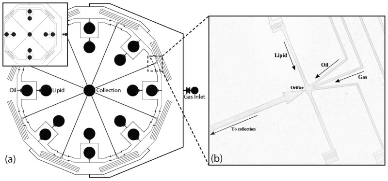
Two microfluidic modules with similar fixed geometries differing in number of orifices (four and eight) were fabricated to investigate the effects of multiple orifices on parallel microbubble generation. Each device consists of three PDMS levels; Fig. 1 shows a schematic for the top level of each array. Both modules share a radial design, having an inner diameter of 33 mm between opposite orifices, with all orifices producing dual-layer microbubbles into outlet channels that flow to a central reservoir. Monodispersity is maintained by an even distribution of gas, oil and lipid solution to all orifice chambers using equal microfluidic channel lengths and symmetry, as well as equilibrating features.
Figure 1.
Geometry of the top level of the 4- and the 8-channel multi-array microfluidic module for the generation of dual-layer microbubbles. (a) Schematic view. All channels are rectangular with a height of 25 μm. (b) Image of the hydrodynamic flow-focusing region. Lipid solution, oil, and gas distribution channels measure 50μm, 35 μm, and 35 μm in width and direct flows to orifices 9 μm in width.
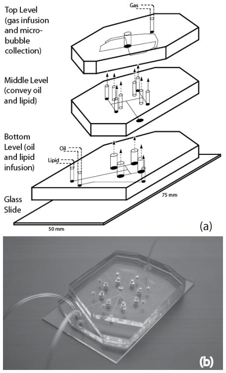
Multiple PDMS levels allowed for fabrication of vertical passages that evenly distribute the fluids to all orifice chambers in the circular arrays. Fig. 2 shows all three levels of the 4-channel microfluidic module. Dual-layer microbubbles are produced at each orifice by flow-focusing microchannels with a central gas channel 35 μm in width flanked by 35 μm wide oil channels and 50 μm wide lipid solution channels, all feeding into orifices approximately 9 μm in width.
Figure 2.
The multilevel microfluidic module. (a) Schematic view of all three levels of the module. Lipid solution and oil are infused through inlets in the bottom level and bifurcate evenly in the bottom and middle levels, respectively, into a number of channels equal to the number of orifices. Microchannels in the top level provide gas infusion and distribution leading to hydrodynamic flow-focusing regions. (b) Image of the assembled 8-channel PDMS device with fluidic connections.
Gas destined for the microbubble core first enters a single inlet on the top PDMS level, bifurcates into a number of channels equal to the number of orifices, and then passes through a series of serpentine channels, serving as resistors, before entering each orifice chamber. It has been noted in past studies that crosstalk between orifices disrupts equilibrium production and decreases the monodispersity of generated microbubbles far more than in droplet generation systems due to high sensitivity to gas compressibility.18 Extended distribution channels in our module increase resistance to make gas flow to each orifice more independent from the rest and microbubble generation less susceptible to fluid disruption caused by neighboring production and sources.31,32 Overall length of the serpentine channels was limited by the diameter (3 inches) of the silicon wafer used during photolithography. Distance traveled between inlet and each orifice is 87 mm and 106 mm for 4- and 8-channel array, respectively; resistor channels extend 50 mm for both 4- and 8-channel arrays.
Oil and lipid solution both enter the bottom PDMS level and bifurcate in the middle and bottom levels, respectively, to reach vertical passages, which connect to the top level. These vertical passages are approximately 104 times larger in cross-sectional area than the distribution channels, and thus serve as reservoirs to minimize distribution errors by acting analogous to capacitors in filter networks of electronic circuits. Also like a capacitor, these passages can, for instance, store enough backpressure to allow production to continue for a period of time after stoppage of mechanical infusion of oil and lipid solution, a phenomenon most likely due in part to the natural elasticity of PDMS. Following generation at the orifices, single-file microbubbles flow through larger post-orifice channels 100 μm wide and 16 mm long, allowing time for stabilization prior to collection in the central reservoir. The width and length of these outlet channels were optimized for the highest rates of generation in single-file while preventing aggregation of the microbubbles.33
3. Experimental Section
Microfabrication and Assembly
Microfluidic chips were fabricated using standard soft lithography techniques34, forming negative channels by pouring PDMS over positive SU-8 master molds. Standard prototyping techniques were modified to facilitate bonding between multiple PDMS levels. A consistent mixture of PDMS to curing agent (10:1) was used for all three levels of the device and cured overnight at 70 °C. In a laminar flow chamber, PDMS levels were peeled from their hard masters and inlets and outlet were punched using a blunt 18 G needle, undersized to provide a tight fit for tubing. Individual levels were plasma treated in an air plasma machine (Harrick Plasma) for a minimum of 150 seconds at 250 millitorr and 200 W, and bonded sequentially using transitional spacers for alignment. Injecting 0.01% polyvinyl alcohol solution into the module, then vacuum drying and baking overnight in a 70 °C temperature-controlled dry oven, maintained hydrophilicity of the channel surfaces.
Solutions
Continuous liquid phase, consisting of an aqueous solution of glycerol/propylene-glycol (Sigma) mixed with the stabilizing lipids DSPC (1,2-distearoyl-sn-glycero-3-phosphocholine, Avanti Polar Lipids) and DSPE-PEG2000 (1,2-distearoyl-sn-glycero-3-phosphoethanolamine-N-[methoxy(polyethylene glycol)-2000], Avanti Polar Lipids), was adapted from Hettiarachchi et al.29. In sum, DSPC and DSPE-PEG2000 were combined at a molar ratio of 9:1 before dissolving in chloroform (CHCl3, Sigma). Following chloroform evaporation, water was added and the solution was sonicated in a general-purpose ultrasonic cleaner (Model 150 HT, AquaSonic) for 20 minutes at 50°C in order to disperse lipid molecules. Glycerol and propylene glycol were added to make 10% solution. Nonionic surfactant (Pluronic F-68, Sigma) was then added at a 1:10 volumetric ratio to improve shell stability. Mild vortex for one minute and a second sonication for 10 minutes followed to ensured complete mixture. The intermediate oil phase consists of triacetin oil (Glyceryl triacetate, Sigma) mixed with Oil Blue N dye (Sigma) at a concentration of .01 mg mL−1.29
General Equipment and Procedures
Microfluidic modules were mounted on an inverted microscope (IX71, Olympus) for viewing purposes. Pressurized nitrogen (N2, Airgas) was supplied to the module via flexible tubing and controlled by a Swagelok analytic regulator with an Ashcroft 30 PSI gauge, while both continuous liquid phase and oil solutions were pumped at constant flow rates using digitally controlled syringe pumps (Pico Plus, Harvard Apparatus). All fluids were introduced into the module via Tygon Microbore tubing plugged into punched inlets. A high-speed camera (V310 Phantom, Vision Research) was used to record videos of dual-layer microbubble generation at the flow-focusing region of each orifice (for a total of four or eight videos per flow condition). Image J (NIH) was then used to determine generation rates f (bubbles per second, or Hz) and microbubble diameters D (μm) from the videos for each orifice. The pooled generation rate fp for all orifices at a given flow condition was calculated as the sum of individual generation rates, and the pooled microbubble diameter Dp was determined as the weighted average of the diameters generated at individual orifices using generation rates as the weighting factors,
The pooled standard deviation sp of the diameter of microbubbles generated at each flow condition was then calculated as
where s2 represents the variance of the diameter of microbubbles generated at a given orifice. Lastly, the pooled polydispersity index for all orifices at each flow condition was determined from the pooled standard deviation and the pooled microbubble diameter as σp = sp/Dp*100%.
4. Results and Discussion
4.1 Scalable Production of Dual-Layer Microbubbles
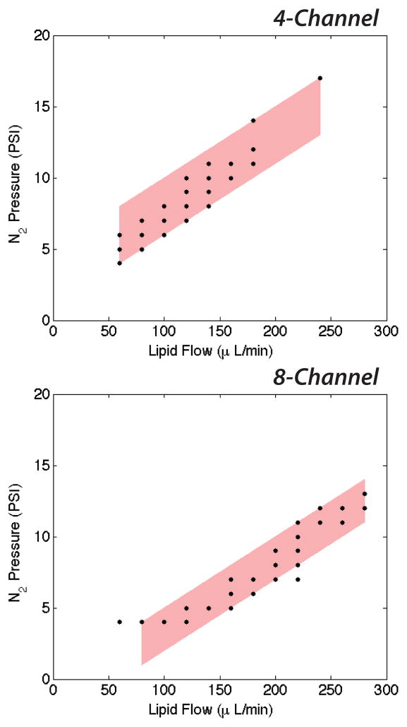
Production was defined as single-file generation of monodisperse, dual-layer microbubbles at all orifices at steady-state, as shown in a 4-channel device in Fig. 3. Optimization of the post-orifice channel geometry enabled production at high generation rates by minimizing contact interactions that cause the microbubbles to coalesce in the high flow velocity environment of the expansion chamber.29 Shown in Fig. 4, consistent zones of production emerged in both the 4- and the 8-channel device. To stably generate dual-layer microbubbles, the 4-channel arrangement tends to require more N2 pressure than the 8-channel, presumably a result of increased outlet resistance due to fewer outlet channels, and less lipid phase flow.
Figure 3.
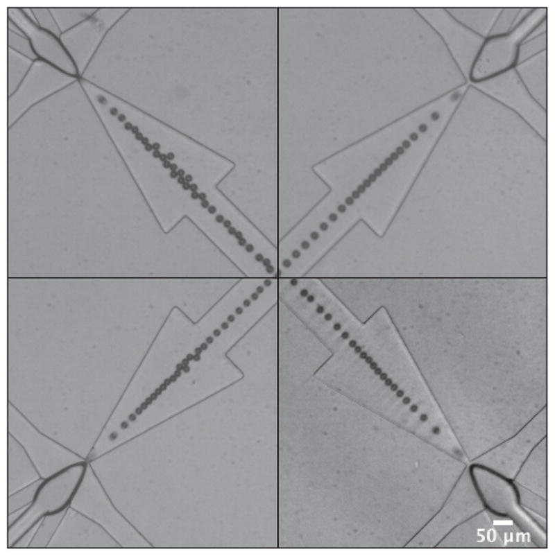
Representative images showing single-file production of monodisperse, dual-layer microbubbles at steady-state in a 4-channel device. Dual-layer microbubbles shear off individually following a protrude-and-retract mechanism, characteristic of geometry-controlled formation. Imperfections in the channel geometries and minor variations in the widths of the orifices caused qualitative differences in the shapes of the dispersed phase bulb and quantitative differences in the generation rates, diameters and pooled monodispersity. These images show microbubbles of a mean diameter of 20.4 ± 1.1 μm, σp = 5.3%. Scale bar is 50 μm.
Figure 4.
Expected zones of production of dual-layer microbubbles in the 4- and the 8-channel device. The 8-channel arrangement expectedly requires more continuous phase flow to achieve stable generation, while the 4-channel arrangement requires more dispersed phase pressure due to increased outlet resistance.
By modulating the flow rate parameters we control the generation of dual-layer microbubbles in a range of sizes. Consistent with previous studies16,29, increasing the N2 pressure (PG) while maintaining the lipid phase flow (QL) tends to increase the microbubble diameter (D); conversely, increasing QL while maintaining PG decreases D. As a further investigation of the influence of the flow rate parameters, we calculated the volumetric flow rate (μl min−1) of the dispersed N2 phase as QG = (πDp3/6)*fp, appropriately converted, in order to evaluate the effect of the dimensionless flow rate ratio ϕ = QL/QG on the production characteristics. An interesting trend emerged at low values of ϕ, in that increasing either QL or PG, while holding the other constant, tended to decrease D for higher overall system pressures (Table 1).
Table 1.
Selected generation data and sequence of images for dual-layer microbubbles produced under varying input flow conditions. Scale bar is 50 μm.
| 4 Channel | 8 Channel | ||||||||||
|---|---|---|---|---|---|---|---|---|---|---|---|
|
| |||||||||||
| Lipid (μl min−1) | N2 (PSI) | Rate (Hz) | Diameter (μm) | PDI | ϕ | Lipid (μl min−1) | N2 (PSI) | Rate (Hz) | Diameter (μm) | PDI | ϕ |
| 140 | 10 | 16000 | 24.6 ± 1.0 | 4.0 | 19 | 220 | 9 | 16400 | 28.5 ± 2.5 | 8.8 | 18 |
| 160 | 10 | 14200 | 21.9 ± 0.9 | 4.0 | 34 | 220 | 11 | 22200 | 28.5 ± 2.0 | 7.0 | 14 |
| 160 | 11 | 52200 | 20.4 ± 1.1 | 5.3 | 11 | 240 | 11 | 31900 | 25.1 ± 1.7 | 6.6 | 15 |
| 180 | 12 | 64700 | 18.6 ± 1.7 | 9.1 | 14 | 240 | 12 | 103300 | 21.8 ± 1.2 | 5.7 | 7 |
| 240 | 17 | 65800 | 22.3 ± 1.7 | 7.6 | 10 | 280 | 12 | 107000 | 21.2 ± 1.8 | 8.3 | 9 |
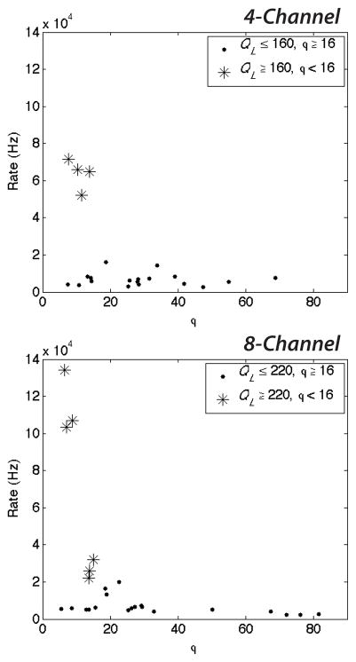
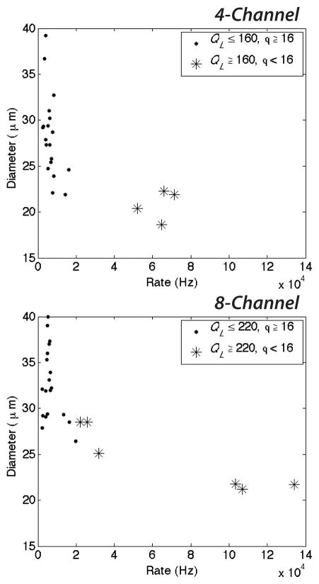
These higher system pressures (increased QL) coupled with low values of ϕ reduce the diameter of microbubbles and increase the generation rate (Fig. 5 and 6). At high QL and ϕ < 16, both the 4- and 8-channel devices generate microbubbles in excess of 2 × 10⁴ Hz, as shown in Fig. 5. Decreasing the dimensionless flow rate ratio further (ϕ < 10 for the 8-channel arrangement) while maintaining a high continuous lipid phase flow enables the production of dual-layer microbubbles in excess of 5 × 10⁴ Hz for the 4-channel arrangement and in excess of 105 Hz for the 8-channel. These production rates are over 50–100 times greater than those generation rates previously observed for multilayer microbubbles in a single channel arrangement by Hettiarachchi et al.29. At these generation rates, microbubble diameters decreased to a range of 18.6–22.3 μm (Fig. 6).
Figure 5.
Generation rate as a function of the ratio of the continuous lipid flow to the dispersed N2 flow, ϕ = QL/QG. Decreasing ϕ quickens the generation rate for high continuous phase flows. Dual-layer microbubbles accumulate at rates in excess of 5 × 10⁴ Hz in the 4-channel arrangement and in excess of 105 Hz in the 8-channel for very low values of ϕ and high QL.
Figure 6.
Microbubble diameter as a function of the generation rate. Increasing the generation rate tends to decrease the microbubble diameter. At high continuous phase flows QL and low values of the dimensionless flow rate ratio ϕ, the generation rate quickens substantially and microbubbles decrease in size to a range of 18.6–22.3μm.
It is worth noting that the observed high QL required for mass production of dual-layer microbubbles corresponds to an elevated capillary number Ca = ηV/γEQ, where η and V represent the viscosity and superficial velocity of the continuous outer phase and γEQ represents the equilibrium surface tension between fluid phases, relative to other flow conditions. It is known that a number of distinct droplet formation regimes–including geometry-controlled, dripping, and jetting–can be accessed by modulating the capillary number in flow-focusing microfluidic devices.35–37 Anna and Mayer35, for instance, observed transitions from geometry-controlled breakup to dripping to jetting at capillary numbers of around Ca ~ 0.1 and Ca ~ 0.2, respectively, in liquid-liquid flows with no surfactants present (the capillary numbers at which transitions occurred increased as surfactant was added). While the mechanics of bubble formation differ from those of droplet formation, it stands to reason that similar transitions should occur in bubbles, though at currently unknown ranges of capillary number. Here we constrain our device operation to the geometry-controlled regime due to limitations in the strength of the bonds between PDMS levels (preventing much further increase in the continuous phase flow). Transitioning the device instead into the dripping regime should, based on results in droplets, significantly increase the per-channel generation rate and decrease the size of the dual-layer microbubbles to optimize for clinical use.
4.2 Monodispersity
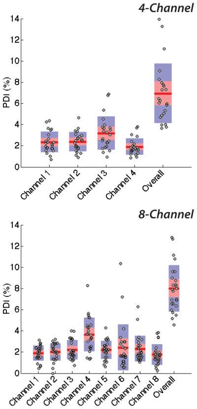
The modules in this study generated dual-layer microbubbles with pooled polydispersity indexes of 6.9 and 8.0 percent overall over four and eight channels, respectively (combined, σp,mean < 7.5%), and of 9.0 and 8.4 percent in the high-speed regime. Qualitative pressure differences at the bubble-producing regions were observed as a result of imperfections in the channel geometries, compounded over the channel lengths, and deviations in the widths of orifices among a device, due to limits in precision of current soft lithography processes. Shown in Fig. 3, at equilibrium, the shapes of the dispersed phase tips vary and accordingly affect the generation rate and diameter of multilayer microbubbles out of each orifice. These imperfections and variations elevated pooled levels of monodispersity over those of individual channels: using the flow-focusing technique, we observed a mean single-channel polydispersity index of less than 2.4 percent (σmean < 2.4%). Shown in Figure 7, generation from individual channels is consistently monodisperse, with relatively little spread in the data relative to data from the overall device. That monodispersity lessened as data from individual channels was pooled supports the growing push in microfluidics for more reproducible and precise manufacturing techniques, such as hot embossing in plastics or glass etching. As per the standard convention of the field, we prototyped in PDMS using soft lithography and observed, for example, a coefficient of variation of nearly 9 percent among orifices (N = 8) averaging 9 μm in diameter.
Figure 7.
Single-channel polydispersities and pooled polydispersity over the 4- and the 8-channel device. Individual channels of each scale-up device generate dual-layer microbubbles with respective mean polydispersity indexes of 2.5% and 2.3%, quite monodisperse and well below respective overall pooled polydispersity indexes of 6.9% and 8.0%.
4.3 Size Optimization
Previous studies have stated the desired size for an intravenous vehicle to be less than 6 μm38 owing to capillary size. Although our device was indeed capable of producing dual-layer microbubbles in this size range, such small sizes arrived at a cost of production rate, the primary goal of this manuscript. Our high-speed diameter range of 18.6–22.3 μm does however represent an over five-fold improvement in size over previous microfluidic scale-up systems19,20, indicating that scale-up for high-output production need not require a trade-off in size. Future work must reduce the size of our dual-layer microbubble to a medically-acceptable diameter range (as ideally these vesicles would be approximately 16 microns smaller than our system is currently optimized for) while maintaining the clinical-scale production and monodispersity achieved here. In order to achieve both suitable microbubble diameters and clinical-scale generation rates, higher gas pressures and flow rates will be necessary and are difficult to obtain with the current device due to observed manufacturing limitations. The ideal microfluidic method will likely require more precise manufacturing techniques beyond soft lithography prototyping in PDMS, such as the technique of hot embossing, discussed below.
4.4 Manufacturability
The microfluidic module presented here prototypes functional design using standard soft lithography techniques and PDMS. These materials lack durability and the methods require significant fabrication time, problematic for translation into industry production. The manufacturability of this device would improve when combined with durable plastics and high throughput fabrication methods capable of micron-size channel widths. One such method, hot embossing is capable of reproducing large numbers of identical microfluidic chips in a time-efficient manner. Plastics commonly used, including poly(methyl methacrylate), are capable of withstanding high pressures while at the same time minimizing the diffusion of gas; however new techniques for bonding multi-level microfluidic chips will need to be developed in order to apply this technique to devices like our own.
5. Conclusion
Our multi-array microfluidic module presents a system capable of generating large amounts of multilayer microbubbles, with good monodispersity, for combined imaging and drug delivery. Future work must aim to reduce the size of the multilayer microbubble further while maintaining the high-speed production demonstrated in this manuscript. Transitioning the device into the dripping regime by elevating the capillary number would likely achieve this goal, assuming proper manufacture of the multilevel device to avoid blowouts and channel flex.
Relatively straightforward modifications in the design of the microfluidic module presented here would enable the scaled-up production of single-layer microbubbles or single- or dual-layer droplets for a variety of purposes, both medical and biochemical. Further, given a larger footprint, our radial design lends itself to expansion into any 2N number of channels to further increase the throughput, without necessitating additional PDMS levels or complex changes in the fabrication.
Supplementary Material
Acknowledgments
The authors would like to thank Dr. Kanaka Hettiarachchi of our BioMiNT lab UC Irvine for prior contributions and for discussions pertaining to the project. This project was funded by the National Institutes of Health, Grant #1 RO1 EB008733-01A1.
Contributor Information
Michael R. Kendall, Department of Biomedical Engineering, University of California-Irvine, 3406 Engineering Hall, Irvine, CA, 92697 (USA).
David Bardin, Department of Biomedical Engineering, University of California-Irvine, 3406 Engineering Hall, Irvine, CA, 92697 (USA).
Roger Shih, Department of Biomedical Engineering, University of California-Irvine, 3406 Engineering Hall, Irvine, CA, 92697 (USA).
Paul A. Dayton, Email: padayton@bme.unc.edu, Joint Dept. of Biomedical Engineering, University of North Carolina-North Carolina State University, 304 Taylor Hall, CB 7575, Chapel Hill, NC 27599 (USA)
Abraham P. Lee, Email: aplee@uci.edu, Department of Biomedical Engineering, University of California-Irvine, 3406 Engineering Hall, Irvine, CA, 92697 (USA)
References
- 1.Gessner R, Dayton PA. ‘Advances in molecular imaging with ultrasound’. Mol Imaging. 2010;9(3):117–127. [PMC free article] [PubMed] [Google Scholar]
- 2.Kaul S. ‘Myocardial contrast echocardiography: a 25-Year retrospective’. Circulation. 2008;118:291–308. doi: 10.1161/CIRCULATIONAHA.107.747303. [DOI] [PubMed] [Google Scholar]
- 3.Dayton PA, Rychak JJ. ‘Molecular ultrasound imaging using microbubble contrast agents’. Front Biosci. 2007;12:5124–5142. doi: 10.2741/2553. [DOI] [PubMed] [Google Scholar]
- 4.Klibanov AL. ‘Targeted delivery of gas-filled microspheres, contrast agents for ultrasound imaging’. Adv Drug Deliv Rev. 1999;37(1–3):139–157. doi: 10.1016/s0169-409x(98)00104-5. [DOI] [PubMed] [Google Scholar]
- 5.Grinstaff MW, Suslick KS. ‘Air-filled proteinaceous microbubbles: synthesis of an echo-contrast agent’. Proc Natl Acad Sci. 1991;88:7708–7710. doi: 10.1073/pnas.88.17.7708. [DOI] [PMC free article] [PubMed] [Google Scholar]
- 6.Stride E, Edirisinghe M. ‘Novel preparation techniques for controlling microbubble uniformity: a comparison’. Med Biol Eng Comput. 2009;47:883–892. doi: 10.1007/s11517-009-0490-8. [DOI] [PubMed] [Google Scholar]
- 7.Talu E, Hettiarachchi K, Zhao S, Powell RL, Lee AP, Longo ML, Dayton PA. ‘Tailoring the size distribution of ultrasound contrast agents: possible method for improving sensitivity in molecular imaging’. Mol Imaging. 2007;6(6):384–392. [PMC free article] [PubMed] [Google Scholar]
- 8.Talu E, Hettiarachchi K, Powell RL, Lee AP, Dayton PA, Longo ML. ‘Maintaining monodispersity in a microbubble population formed by flow-focusing’. Langmuir. 2008;24(5):1745–1749. doi: 10.1021/la703065v. [DOI] [PMC free article] [PubMed] [Google Scholar]
- 9.Kaya M, Feingold S, Hettiarachchi K, Lee AP, Dayton PA. ‘Acoustic responses of monodisperse lipid-encapsulated microbubble contrast agents produced by flow focusing’. Bubble Sci Eng Technol. 2010;2(2):33–40. doi: 10.1179/175889610x12779105661532. [DOI] [PMC free article] [PubMed] [Google Scholar]
- 10.Chomas JE, Dayton P, May D, Ferrara K. ‘Threshold of fragmentation for ultrasonic contrast agents’. J Biomed Opt. 2001;6(2):141–150. doi: 10.1117/1.1352752. [DOI] [PubMed] [Google Scholar]
- 11.de Jong N, Bouakaz A, Frinking P. ‘Basic acoustic properties of microbubbles’. Echocardiography. 2002;19(3):229–240. doi: 10.1046/j.1540-8175.2002.00229.x. [DOI] [PubMed] [Google Scholar]
- 12.Dayton PA, Allen JS, Ferrara KW. ‘The magnitude of radiation force on ultrasound contrast agents’. J Acoust Soc Am. 2002;112(5 Pt 1):2183–2192. doi: 10.1121/1.1509428. [DOI] [PubMed] [Google Scholar]
- 13.Ganan-Calvo AM, Gordillo JM. ‘Perfectly monodisperse microbubbling by capillary flow focusing’. Phys Rev Lett. 2001;87:274501. doi: 10.1103/PhysRevLett.87.274501. [DOI] [PubMed] [Google Scholar]
- 14.Garstecki P, Gitlin I, DiLuzio W, Whitesides GM, Kumacheva E, Stone HA. ‘Formation of monodisperse bubbles in a microfluidic flow-focusing device’. Appl Phys Lett. 2004;85(13):2649. [Google Scholar]
- 15.Gordillo JM, Cheng Z, Ganan-Calvo AM, Márquez M, Weitz DA. ‘A new device for the generation of microbubbles’. Phys Fluids. 2004;16(8):2828–2834. [Google Scholar]
- 16.Hettiarachchi K, Talu E, Longo ML, Dayton PA, Lee AP. ‘On-chip generation of microbubbles as a practical technology for manufacturing contrast agents for ultrasonic imaging’. Lab Chip. 2007;7:463–468. doi: 10.1039/b701481n. [DOI] [PMC free article] [PubMed] [Google Scholar]
- 17.Castro-Hernández E, van Houve W, Lohse D, Gordillo JM. ‘Microbubble generation in a co-flow device operated in a new regime’. Lab Chip. 2011;11:2023–2029. doi: 10.1039/c0lc00731e. [DOI] [PubMed] [Google Scholar]
- 18.Hashimoto M, Shevkoplyas SS, Zasonska B, Szymborski T, Garstecki P, Whitesides GM. ‘Formation of bubbles and droplets in parallel, coupled flow-focusing geometries’. Small. 2008;4(10):1795–1805. doi: 10.1002/smll.200800591. [DOI] [PubMed] [Google Scholar]
- 19.Nisisako T, Torii T. ‘Microfluidic large-scale integration on a chip for mass production of monodisperse droplets and particles’. Lab Chip. 2008;8:287–293. doi: 10.1039/b713141k. [DOI] [PubMed] [Google Scholar]
- 20.Romanowsky MB, Abate AR, Rotem A, Holtze C, Weitz DA. ‘High throughput production of single core double emulsions in a parallelized microfluidic device’. Lab Chip. 2012;12:802–807. doi: 10.1039/c2lc21033a. [DOI] [PubMed] [Google Scholar]
- 21.Ellegala DB, Leong-Poi H, Carpenter JE, Klibanov AL, Kaul S, Shaffrey ME, Sklenar J, Lindner JR. ‘Imaging tumor angiogenesis with contrast ultrasound and microbubbles targeted to αvβ3’. Circulation. 2003;108:336–341. doi: 10.1161/01.CIR.0000080326.15367.0C. [DOI] [PubMed] [Google Scholar]
- 22.Villanueva FS, Wagner WR. ‘Ultrasound molecular imaging of cardiovascular disease’. Nat Clin Pract Cardiovasc Med. 2008;5:S26–S32. doi: 10.1038/ncpcardio1246. [DOI] [PMC free article] [PubMed] [Google Scholar]
- 23.Kiessling F, Fokong S, Koczera P, Lederle W, Lammers T. ‘Ultrasound microbubbles for molecular diagnosis, therapy, and theranostics’. J Nucl Med. 2012;53(3):345–348. doi: 10.2967/jnumed.111.099754. [DOI] [PubMed] [Google Scholar]
- 24.Tartis MS, McCallan J, Lum AF, LaBell R, Steiger SM, Matsunaga TO, Ferrara KW. ‘Therapeutic effects of paclitaxel-containing ultrasound contrast agents’. Ultrasound Med Biol. 2006;32(11):1771–1780. doi: 10.1016/j.ultrasmedbio.2006.03.017. [DOI] [PubMed] [Google Scholar]
- 25.Cochran MC, Eisenbrey J, Ouma RO, Soulen M, Wheatley MA. ‘Doxorubicin and paclitaxel loaded microbubbles for ultrasound triggered drug delivery’. Int J Pharm. 2011;414(1–2):161–170. doi: 10.1016/j.ijpharm.2011.05.030. [DOI] [PMC free article] [PubMed] [Google Scholar]
- 26.Lawrie A, Brisken AF, Francis SE, Cumberland DC, Newman CM. ‘Microbubble-enhanced ultrasound for vascular gene delivery’. Gene Ther. 2000;7(23):2023–2027. doi: 10.1038/sj.gt.3301339. [DOI] [PubMed] [Google Scholar]
- 27.Shohet RV, Chen S, Zhou YT, Wang Z, Meidell RS, Unger RH, Grayburn PA. ‘Echocardiographic destruction of albumin microbubbles directs gene delivery to myocardium’. Circulation. 2000;101:2554–2556. doi: 10.1161/01.cir.101.22.2554. [DOI] [PubMed] [Google Scholar]
- 28.Seo M, Gorelikov I, Williams R, Matsuura N. ‘Microfluidic assembly of monodisperse, nanoparticle-incorporated perfluorocarbon microbubbles for medical imaging and therapy’. Langmuir. 2010;26(17):13855–60. doi: 10.1021/la102272d. [DOI] [PubMed] [Google Scholar]
- 29.Hettiarachchi K, Zhang S, Feingold S, Dayton PA, Lee AP. ‘Controllable microfluidic synthesis of multiphase drug-carrying lipospheres for site-targeted therapy’. Biotechnol Prog. 2009;25(4):938–945. doi: 10.1002/btpr.214. [DOI] [PMC free article] [PubMed] [Google Scholar]
- 30.DEFINITYR package insert, Lantheus Medical Imaging, Inc., c 2012.
- 31.Jousse F, Lian G, Janes R, Melrose J. ‘Compact model for multi-phase liquid-liquid flows in micro-fluidic devices’. Lab Chip. 2005;5:646–656. doi: 10.1039/b416666c. [DOI] [PubMed] [Google Scholar]
- 32.Barbier V, Willaime H, Tabeling P, Jousse F. ‘Producing droplets in parallel microfluidic systems’. Phys Rev E. 2006;74:046306. doi: 10.1103/PhysRevE.74.046306. [DOI] [PubMed] [Google Scholar]
- 33.Sullivan M, Moore K, Stone HA. ‘Transverse instability of bubbles in viscoelastic channel flows’. Phys Rev Lett. 2008;101(24):244503. doi: 10.1103/PhysRevLett.101.244503. [DOI] [PubMed] [Google Scholar]
- 34.Xia Y, Whitesides GM. ‘Soft lithography’. Annu Rev Mater Sci. 1998;28:153–184. [Google Scholar]
- 35.Anna SL, Mayer HC. ‘Microscale tipstreaming in a microfluidic flow focusing device’. Phys Fluids. 2006;18:121512. [Google Scholar]
- 36.Cubaud TC, Mason TG. ‘Capillary threads and viscous droplets in square microchannels’. Phys Fluids. 2008;20:053302. [Google Scholar]
- 37.Bardin D, Martz TD, Sheeran PS, Shih R, Dayton PA, Lee AP. ‘High-speed, clinical-scale microfluidic generation of stable phase-change droplets for gas embolotherapy’. Lab Chip. 2011;11:3990–3998. doi: 10.1039/c1lc20615j. [DOI] [PMC free article] [PubMed] [Google Scholar]
- 38.Kripfgans OD, Fowlkes JB, Miller DL, Eldevik OP, Carson PL. ‘Acoustic droplet vaporization for therapeutic and diagnostic applications’. Ultrasound Med Biol. 2000;26(7):1177–1189. doi: 10.1016/s0301-5629(00)00262-3. [DOI] [PubMed] [Google Scholar]
Associated Data
This section collects any data citations, data availability statements, or supplementary materials included in this article.


