Abstract
We present a boundary-element method (BEM) implementation for accurately solving problems in biomolecular electrostatics using the linearized Poisson–Boltzmann equation. Motivating this implementation is the desire to create a solver capable of precisely describing the geometries and topologies prevalent in continuum models of biological molecules. This implementation is enabled by the synthesis of four technologies developed or implemented specifically for this work. First, molecular and accessible surfaces used to describe dielectric and ion-exclusion boundaries were discretized with curved boundary elements that faithfully reproduce molecular geometries. Second, we avoided explicitly forming the dense BEM matrices and instead solved the linear systems with a preconditioned iterative method (GMRES), using a matrix compression algorithm (FFTSVD) to accelerate matrix-vector multiplication. Third, robust numerical integration methods were employed to accurately evaluate singular and near-singular integrals over the curved boundary elements. Finally, we present a general boundary-integral approach capable of modeling an arbitrary number of embedded homogeneous dielectric regions with differing dielectric constants, possible salt treatment, and point charges. A comparison of the presented BEM implementation and standard finite-difference techniques demonstrates that for certain classes of electrostatic calculations, such as determining absolute electrostatic solvation and rigid-binding free energies, the improved convergence properties of the BEM approach can have a significant impact on computed energetics. We also demonstrate that the improved accuracy offered by the curved-element BEM is important when more sophisticated techniques, such as non-rigid-binding models, are used to compute the relative electrostatic effects of molecular modifications. In addition, we show that electrostatic calculations requiring multiple solves using the same molecular geometry, such as charge optimization or component analysis, can be computed to high accuracy using the presented BEM approach, in compute times comparable to traditional finite-difference methods.
Keywords: fast solver, solvation, FFTSVD
Introduction
Continuum theories of solvation have become common tools for molecular modeling and have led to an improved understanding of electrostatic interactions in biomolecular systems [1-3]. One of the most popular models of continuum solvation treats a molecule and its solvent environment as homogeneous regions of low- and high-dielectric constants respectively, with embedded point charges in the low-dielectric region representing the molecular charge distribution and Debye–Hückel theory optionally used to model the effect of salt in at least part of the high-dielectric region. The Poisson–Boltzmann equation, which governs this continuum model, has received much attention in recent years, especially in its linearized approximation [4-6]. The linearized Poisson–Boltzmann equation (LPBE), an elliptic partial differential equation (PDE) [7], is well understood theoretically and can be solved numerically using a variety of techniques including finite-difference methods (FDM) [8-16], finite-element methods (FEM) [17-22], and boundary–element methods (BEM) [23-36].
Boundary-element methods possess several properties that make them an attractive alternative for solving the LPBE with regions of homogeneous dielectric [37]. The focus on discretizing the actual two-dimensional boundary surfaces rather than three-dimensional volume regions may be beneficial, in and of itself, as the boundary geometry can be treated exactly [38-40]. Furthermore, the dimensionality reduction may allow for problems to be solved with a smaller number of degrees of freedom. Moreover, boundary methods inherently capture the correct zero-potential condition at infinity. In addition, the effects of point charges are modeled exactly rather than being approximated by grid-projected charges.
In general, boundary-element methods require sophisticated numerical techniques in order to obtain a favorable tradeoff between accuracy, flexibility, and computational cost. Consequently, four enabling technologies were developed or synthesized here in order to enable a BEM solver for biomolecule continuum electrostatics capable of solving a wide variety of molecular geometries to high precision. Three of the four technologies have been studied in detail previously, and our work in these areas [40-43] has built on those efforts [44]. The calculations described in this paper are, to our knowledge, the first that combine all three of these well-studied technologies, and demonstrate that their combination allows BEM to reach levels of convergence previously unrealizable in BEM or other methods using only workstation-level computational resources. The fourth technology, which represents a novel extension of relatively well known integral-equation formulations, allows the high-accuracy-capable BEM to simulate problems identical to those commonly solved using well-known methods.
A principal development applied here was the use of surface discretizations that allowed for exact representation of curved molecular surfaces [39,40]. Exact surfaces are important for a biomolecule BEM because solution accuracy depends strongly on the quality of the surface representation. In this work, and in most others, the dielectric and ion-exclusion surfaces are described according to one of two definitions. Solvent-accessible surfaces [45] are defined as a union of spheres, where the atomic radii are expanded by a probe sphere's radius. Molecular surfaces [46] represent the surface of closest approach of a probe sphere rolled over a union of spheres representing a molecule. These curved molecular surfaces, which consist of portions of spheres and tori, are analytically defined [38] but often are difficult to discretize because the surfaces have cusps and singularities. These discontinuities in the surface normal complicate the implementation of some BEM approaches, and therefore methods for generating modified, smoothed molecular surfaces have been developed [31,39]. Most boundary-element methods for solving the LPBE represent these surfaces approximately using large numbers of planar triangular elements that can never exactly capture the curved geometries. The importance of using curved elements has already been discussed [40, 44, 47], but most previous implementations have introduced other surface approximations. For example, other work has modified the molecular surface definition to avoid generating singularities and thin regions, used elements with low-order curvature that cannot accurately represent spheres or tori, or discretized surfaces using standard spherical triangles that cannot exactly represent the intersections between atoms. In this paper, the accessible and molecular surfaces are represented essentially exactly using curved boundary-element discretizations that accurately reproduce even singularities, cusps, and thin regions [40]. The surface discretizations described here generate the exact solvent-excluded-surface described originally by Richards, with self-intersecting reentrant surfaces removed in the same fashion as Connolly [38, 48]. The resulting piecewise-smooth surfaces suffice for existence of a unique solution [37]. Although the exact solutions may exhibit singular behavior near discontinuities in the surface normal [49], one may still use a piecewise-constant basis set to approximate the space of solutions. Recently, Ong and collaborators have introduced singular basis functions for surface normal discontinuities, and these functions may allow higher-fidelity representation of the true surface distributions [50, 51].
Another important technology was a matrix compression algorithm that allows the BEM equations to be solved with an improved tradeoff between compute time and memory use. In the BEM, discretization of surface integral equations gives rise to dense linear systems of equations. As a result, memory costs scale quadratically in the number of unknowns. In contrast, the FDM and FEM generate sparse matrices that reflect the local nature of the differential operators. Solving the BEM linear system by matrix factorization requires O(n3) time, where n is the number of unknowns. Computational costs rapidly become prohibitive for systems with more than 104 unknowns, which is currently insufficient to accurately model biological macromolecules such as proteins. The quadratic memory and cubic time costs can be reduced to linear or near-linear complexity by combining two approximation schemes. First, the linear systems are solved to a specified numerical tolerance using Krylov subspace iterative methods such as the conjugate gradient method (CG) or the generalized minimum residual algorithm (GMRES) [52]. Every iteration of a dense Krylov subspace method requires the multiplication of a vector by the BEM matrix, costing a prohibitive O(n2) memory and time. A second approximation reduces the matrix-vector product cost by interpreting the formation of the product as an n-body potential calculation [53]. This interpretation enables the use of techniques such as multipole methods [28,30,32,33,53-55], or multiscale methods [31], to reduce the solution costs to O(n) or O(n log n) in both memory and time. Multipole methods require specialized expansions for every governing equation, and expansions for the LPBE have been developed in recent years [56]. One disadvantage of most multipole methods is that the computational costs grow rapidly when improving accuracy [57]; in particular, the fast-multipole method (FMM) uses dense translation operations between multipole and local expansions, which have motivated the development of more efficient techniques [43, 57, 58]. In this work, the dense linear systems that arise in the BEM are efficiently solved using preconditioned Krylov subspace methods and the FFTSVD matrix compression algorithm [43]. The FFTSVD algorithm efficiently sparsifies the dense BEM matrix, and memory and time requirements scale effectively linearly in the number of boundary elements. This fast BEM technique can be applied without modification to compress all of the integral operators in biomolecule electrostatics. Furthermore, the dense translation operations that dominate the FMM computational cost are replaced in the FFTSVD method with more efficient diagonal translations, allowing for a better tradeoff between computational expense and accuracy.
Given surface elements that can exactly represent molecular geometries and a means of compressing the dense linear systems of BEM equations, technologies needed to be developed to accurately and robustly compute certain matrix elements of these compressed integral operators. The computation of these elements requires the integration of singular or near-singular functions over the elements used to discretize the boundary surfaces. These integrations can be interpreted as the calculation of the potential at an evaluation point due to a charge distribution defined on a boundary element. In contrast, the matrix elements for FDM and FEM problems are relatively easily computed. Although analytical expressions exist for the integral of the Laplace (Poisson) kernel over flat triangular elements [59,60], integration of the LPBE kernel, or integration over general curved domains, requires numerical approximation. When the evaluation point is sufficiently far from the element, quadrature rules can be used to perform numerical integration, even over curved elements [25,27]. However, when the evaluation point is near or on the element, even high-order quadrature rules do not suffice to capture the singularity. The evaluation of near-singular and singular integrals has been noted to be a limiting factor in the accuracy of BEM implementations for molecular electrostatics [29], and a variety of techniques have been developed to either avoid computing these integrals [29] or to approximate them with adaptive quadrature rules [61]. Here, robust methods were used to compute singular and near-singular integrals of the singular Laplace (Poisson) and LPBE Green's functions [40], allowing the presented BEM to achieve exceptional accuracy.
A final and important technology was developed to allow the BEM implementation to efficiently handle a wider variety of molecular topologies. Some Poisson–Boltzmann modeling problems require treatment of multiple embedded or disconnected regions with differing dielectric constants and screening parameters (see references 62 and 35). These features allow the simulation of solvent-filled cavities within macromolecules, salt-filled regions in large cavities, and an ion-exclusion layer, also known as a Stern layer [63], surrounding the molecule with solvent dielectric but no salt. Some studies based on FDM have used an electrostatic model with smoothly varying dielectric [64, 65]; such problems are easily modeled using volume-based methods like FDM or FEM because the dielectric constant and the presence of salt can be assigned to each grid point or volume element independently. This modeling flexibility is a noted advantage for volume-based methods (see, for example, reference 65) relative to boundary-element methods, which are poorly suited to such problems, in general. In this paper we focus exclusively on modeling multiple regions of homogeneous dielectric. Implementing these features using a BEM requires the discretization of every interface between dielectric regions and between those governed by different PDEs. Previous BEM approaches have addressed these limitations by developing specific formulations to treat multiple embedded dielectric regions without salt [62], multiple disconnected dielectric bodies with salt [35,36], and hybrid boundary-element/finite-difference methods to treat ion-exclusion layers [66]. In this work, we present a general boundary-integral approach, based on Green's theorem, that can treat an arbitrary number of embedded regions of homogeneous dielectric with different dielectric constants and possibly salt to represent a wide variety of possible molecular topologies, including ion-exclusion layers and solvent-filled cavities in the solute. Finite-difference and finite-element simulations have long been capable of modeling problems with these features, but this paper presents the first general, detailed derivation for BEM treatment.
We first detail our boundary-element method for solving the linearized Poisson–Boltzmann equation (LPBE) that implements these four enabling technologies, with the ultimate goal of achieving high accuracy given reasonable computational resources. After describing the implementation, we present a set of computational experiments in order to illustrate the accuracy and computational cost of finite-difference and boundary-element method simulations for several categories of calculations. We calculate the electrostatic contributions to free energies of solvation for an analytically solvable sphere geometry, a short peptide derived from an HIV-1 protease substrate site [67], and the barnase–barstar protein complex [68]. We also compute rigid and non-rigid electrostatic binding free energies for the wild-type barnase–barstar complex as well as three single mutants. Solvation calculations demonstrate that the BEM presented here provides better discretization error reduction, or convergence, as a function of compute time as compared to a successive over-relaxation (SOR)-based implementation of the FDM. Rigid-binding results also suggest that the BEM converges more rapidly than FDM. However, when comparing differential rigid binding energies between wild-type and mutant protein complexes, where the structure remains the same except at the site of mutation, even low-resolution finite-difference simulations accurately capture this differential energy. The curved BEM regains an accuracy advantage for differential non-rigid binding calculations, suggesting that the accuracy of finite-difference rigid binding calculations may result from fortuitous error cancellation. Finally, we demonstrate that the BEM implementation offers a clear advantage in accuracy, given comparable simulation time, for calculations that require repeated solution of the same problem geometry with different sets of atomic charges. Electrostatic component analysis [69-71] and charge optimization [72,73] are examples of calculations that fall into this category. Our implementation demonstrates that highly precise continuum-electrostatic calculations are feasible on modern workstations and that such precision can be important for biological investigations.
Theory
Green's theorem integral formulation
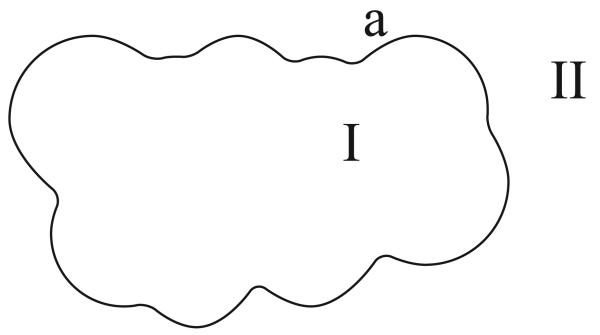
We begin our presentation of the multi-region integral formulation by deriving the one-surface Green's theorem-based integral approach described by Yoon and Lenhoff [74]. This method is also known as the non-derivative Green's theorem formulation [34, 44]. Figure 1 illustrates the problem and notation.
Figure 1.
A one-surface problem in molecular electrostatics. The molecular interior (Region I), containing point charges qi, is surrounded by a salt solution with high dielectric constant and inverse Debye length k (Region II).
A single boundary a divides space into two regions. The molecular interior, labeled region I, has a uniform permittivity ∊I and contains nc discrete point charges. The ith point charge, located at ri, is of value qi. In region I, the electrostatic potential ϕI(r) is governed by a Poisson equation
| (1) |
where δ(r − ri) is the Dirac delta function translated by ri, and all quantities are in the International System of Units (SI). That is, the potential ϕ is in volts, the charges qi are in coulombs (ampere–seconds), and the permittivity ∊I is in farads per meter.
The solvent region II exterior to a represents solvent with mobile ions; we model the region as having a uniform dielectric constant ∊II and an inverse Debye length k, where and is typically around 0.125 Å−1 (NA = Avogadro's number, e = electron charge magnitude, I = ionic strength (in molar), ∊0 = permittivity of the vacuum, k = Boltzmann's constant, T = absolute temperature). In this region, the electrostatic potential ϕII(r) is assumed to obey the linearized Poisson–Boltzmann equation:
| (2) |
The free-space Green's functions for the Poisson and linearized Poisson–Boltzmann equations,
| (3) |
| (4) |
satisfy ∇2GI(r; r′) = −δ(r − r′) and (∇2−k2)GII(r; r′ = −δ(r − r′) respectively. Across the boundary surface a, the electrostatic potential and the normal displacement are continuous [49]. Using the relation D = ∊E, where the electric field E satisfies E = −∇ϕ, we can write the continuity conditions at a point ra on the surface a as
| (5) |
| (6) |
In Equation 6, the normal direction is defined to point into the solvent region.
After specifying the problem domains and boundary conditions, one applies Green's theorem in both regions. Green's theorem,
| (7) |
where Ψ(r) and Φ(r) are two scalar fields, allows the determination of the potential at a point in a volume V given the free-space Green's function for the governing equation in V as well as the potential and its outward normal derivative at the bounding surface Ω.
We first apply Green's theorem to find the potential at a point rI in region I, which has the bounding surface Ω = a. Using the Green's function (Equation 3) and substituting Ψ(r′) = GI(rI; r′), Φ(r′) = ϕI(r′), and Equation 1, we have
| (8) |
In Equation 8 and throughout this section, the normal derivative of GI is taken with respect to the integration variable r′: that is, denotes the potential at rI induced by a normally-oriented unit dipole at r′. Simplifying the left-hand side using the definition of the Green's function,
| (9) |
eliminates the volume integral in Equation 8, and by rearranging terms one obtains an expression for the potential at rI as a function of the solute charge distribution and the boundary conditions:
| (10) |
To apply Green's theorem in region II , one must first bound the region by introducing a hypothetical surface Γ at infinity, and assume the potential obeys regularity conditions at infinity [26] such that the surface integrals over Γ vanish.
Employing the substitutions Ψ(r′) = GII (rII; r′), Φ(r′) = ϕII (r′), Equation 4, and the LPBE Green's function definition, we can write the potential at a point rII in region II as
| (11) |
Notice that the signs of the single- and double-layer integrals are reversed with respect to those in Equation 10. This arises because Green's theorem is initially applied in region II with the surface normals pointing out from region II . The surface normal direction is then reversed so that Equations 10 and 11 share a consistent direction, which is outward from region I . Reversing the surface normal direction changes the sign of the normal derivative terms in the surface integral.
We derive a pair of coupled integral equations by letting the points rI and rII approach a point ra on the surface. Using Equation 10,
| (12) |
| (13) |
The second term in Equation 13 can be interpreted as the potential induced by a dipole layer of charge on the surface. Such a potential is discontinuous as the evaluation point crosses the surface and must be handled with care. We write
| (14) |
where f represents a principal value integral, and we assume that the limit as rI → ra has been taken from the direction opposite the normal. A similar limiting process applied to Equation 11, in which we let rII → ra, yields
| (15) |
Finally, we eliminate the unknowns ϕII (ra) and using the continuity conditions (Equations 5 and 6). Two coupled integral equations result:
| (16) |
| (17) |
Introducing an abbreviated notation allows the equations to be written as
| (18) |
where ϕa and denote the surface potential and normal displacement on a, I denotes the identity operator, ∊I,II abbreviates , and and denote the single- and double-layer operators that compute potential at the surface u due to a monopole or dipole charge density on surface v, given the Green's function GI(r; r′). The operator is defined such that:
| (19) |
similarly,
| (20) |
In Equation 18, we have also defined .
Numerical solution using the boundary-element method
To simultaneously solve Equations 16 and 17 using the boundary-element method (BEM), we first approximate the surface variables ϕI(ra) and as weighted combinations of a set of n basis functions χ1(r), χ2(r),…, χn(r) on the surface:
| (21) |
| (22) |
The unknown weights uk and vk are then found by forcing the integral equation to be satisfied as closely as possible in some choice of metric.
In this work, we discretize the surfaces into a discrete set of np non-overlapping curved boundary elements and use piecewise-constant basis functions that have a value of one on a single element and zero everywhere else:
| (23) |
Defining the integral equation residual to be the difference between the known condition on the surface and the integral operator applied to the approximate solution, one can form a square linear system by forcing the residual to equal zero at the boundary-element centroids, a technique known as centroid collocation [75]. Using the piecewise-constant basis functions and denoting the centroid of element i as rci, the discretized (matrix) form of the operator from Equation 19 has entries
| (24) |
and the double-layer discretized operator similarly has entries
| (25) |
The total matrix equation representing the discretized form of Equation 18 therefore has dimension 2np. Once this equation is solved, the potential anywhere in space may be calculated using the discretized forms of Equations 10 and 11.
Extension to multiple dielectrics, solvent cavities, and ion-exclusion layers
Continuum electrostatic models of biomolecular systems can be defined by multiple embedded regions of differing homogeneous dielectric constant and salt treatment. Integral-equation formulations that can solve these problems often possess a complicated block structure because there exist numerous operators that couple variables on one surface to conditions on other surfaces. To illustrate this block structure, we next present Green's theorem formulations for two-surface and three-surface example problems. We then describe how a tree-based representation of the enclosed regions facilitates the determination of the appropriate Green's theorem-based integral operator for arbitrary multi-region problems.
Two-surface formulation
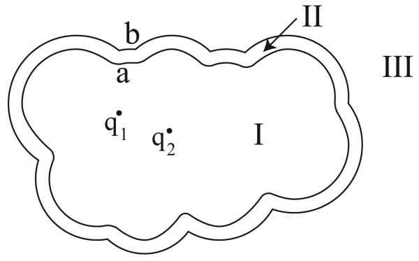
Figure 2 is a schematic of a two-surface problem in molecular electrostatics; salt ions are not permitted to directly reach the molecular surface a, but instead are bounded by an accessible surface b a specified distance outside the molecule. The enclosed volume between the surfaces is termed the ion-exclusion layer. Region I, again representing the molecular interior, has dielectric constant ∊I and nc point charges. The ion-exclusion layer, region II , has dielectric constant ∊II , and in this region, the Laplace equation governs the electrostatic potential. Region III represents solvent with mobile ions and has dielectric constant ∊III (usually the same as ∊II) but contains a Debye–Hückel salt treatment; the potential in this region is governed by the linearized Poisson–Boltzmann equation. This problem has continuity conditions at both surfaces a and b:
| (26) |
| (27) |
| (28) |
| (29) |
The associated integral equations have four surface variables, which are the potential and normal derivative on both surfaces: ϕa, , ϕb, and . The free-space Green's functions in each region are again denoted by G with the region label as subscript: GII (r; r′), for instance, denotes the free-space Laplace Green's function. As in the one-surface derivation, we apply Green's theorem in each region using the appropriate substitutions, let the field points approach the bounding surfaces, and eliminate redundant variables using the continuity conditions. The resulting operator takes the form
 |
(30) |
which can be solved with the boundary-element method described above.
Figure 2.
A two-surface problem in molecular electrostatics. The molecular interior (Region I), containing point charges qi, is surrounded by an ion-exclusion layer with solvent dielectric and no salt (Region II), which in turn is surrounded by solvent with a salt treatment (Region III).
Note that the integral operator contains several zero blocks. These blocks arise from the application of Green's theorem in regions for which one or more surfaces do not form part of that region's bounding surface. For instance, surface b forms no portion of the bounding surface for region I, and consequently variables on surface b contribute nothing to the integral equation derived by applying Green's theorem in region I. Note also that two of the integral equations derive from the application of Green's theorem in region II .
Three-surface formulation
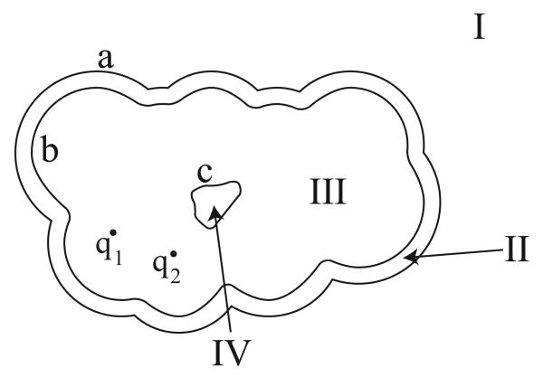
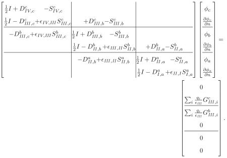
To identify more general trends in the construction of multi-boundary integral operators, we extend the two surface formulation by adding a solvent-filled cavity inside the protein interior (Figure 3). In this problem and for the remainder of this Section, we will follow the convention that region I is the outermost solvent region. The additional region IV has dielectric constant ∊IV (generally equal to ∊I and ∊II), and is not large enough to contain an ion-exclusion surface. Again, we apply Green's theorem in every region, take limits on the surface integrals as the field points approach the boundaries, and enforce continuity conditions. The resulting operator takes the form
 |
(31) |
Figure 3.
A three-surface problem in molecular electrostatics. This geometry is analogous to the two-surface problem (Figure 2) except that a solvent-filled cavity has been added within the molecular interior (Region IV). Note that in contrast to previous examples, the regions and surfaces have been labeled in reverse order.
In this expression, the charges in region III contribute to two of the integral equations, both of which derive from the application of Green's theorem in the region. The point-charge contributions are found by taking limits as the field point in the region approaches the exterior and interior bounding surfaces. Note again that some of the off-diagonal 2 × 2 blocks contain nonzero 1 × 2 blocks. These operators represent the contribution of a region's interior (or exterior) bounding surface to the integral equation derived by letting the field point in the region approach an exterior (or interior) bounding surface.
Tree-based general formulation
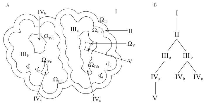
To derive an integral operator for an arbitrary configuration of embedded boundaries with regions of differing homogeneous dielectric, point charges, and salt treatment, we represent the topology using a tree. Traversing the nodes of the tree, irrespective of the order in which they are visited, allows multiplication by the entire integral operator taking into account all necessary interactions. Each node of the tree represents one region, and is associated with a dielectric constant and possibly salt treatment or point charges. The tree is constructed such that the node for a given region X is assigned to be the child of the node corresponding to the region surrounding X. Region I, which is bounded only by a hypothetical surface at infinity, is defined to be the root node. Furthermore, we associate with each node the exterior bounding surface of the corresponding region. Figure 4B is a tree diagram constructed to describe the system shown in Figure 4A.
Figure 4.
Tree representation of a general surface problem. The example molecular geometry shown in (A) might correspond to an encounter complex between two associating proteins (Regions IIIa and IIIb) with point charges qi, surrounded by a single ion-exclusion layer (Region II), which in turn is surrounded by solvent with salt (Region I). The binding partners contain several solvent filled cavities (Regions IVa–c), and one cavity is large enough to contain a small ion-exclusion layer (Region V). The tree representation for this example multi-surface geometry is shown in (B).
The example geometry shown may be representative of an encounter complex in protein–protein binding, where two nearly associated binding partners (Regions IIIa and IIIb) are surrounded by a single ion-exclusion layer (Region II). There are also several solvent-filled cavities present in both binding partners (Regions IVa–c), and one cavity is large enough to contain a small ion-exclusion layer (Region V).
Applying the multi-surface integral operator
A multi-region electrostatics problem with n surfaces generates a system of 2n coupled integral equations. For each surface, one writes Green's theorem for the regions exterior and interior to the surface and takes the appropriate limits as the evaluation points approach the surface. Accordingly, one may refer to the resulting integral equations as the exterior and interior equations corresponding to the surface.
An integral equation derived from an application of Green's theorem contains contributions from the surfaces bounding the region. As an example, consider the interior equation for surface ΩIIIb. Applying Green's theorem in region IIIb defines the potential at a point in this region as a function of the surface potential and its normal derivative on ΩIIIb, ΩIVb, and ΩIVc. Taking the limit of the Green's theorem expression as the field point approaches IIIb, we obtain the interior equation. Clearly, a surface's interior equation contains contributions from the surface as well as its children. Similarly, a surface's exterior equation contains contributions from the surface, its parent, and its siblings. This can be seen by letting the field point approach any of the cavity surfaces.
Multi-surface problems demand that careful attention be paid to the definition of the surface normal. In this work we follow the mathematical convention that a normal always points outward from the finite volume enclosed by the surface. To apply the entire multi-surface operator for an arbitrary problem, we first define a tree such as shown in Figure 4B. The tree is traversed depth first, and at each node we apply several integral operators, which in the discretized problem correspond to dense block matrix–vector multiplications. Because each block multiplication may be interpreted as the computation of the potential at a surface due to a distribution of monopole or dipole charge on another surface, we refer to the two surfaces as the source surface and the destination surface. The set of block multiplications to be performed at every node is determined by the topology of the surfaces, and is defined such that every non-zero block in the integral operator is applied exactly once.
We define four types of block integral operators: the self-surface interior operator, the self-surface exterior operator, the non-self interior operators, and the non-self exterior operators. As previously discussed, each operator represents an interaction between two surfaces. The labels interior and exterior specify whether the integral operator arises from an application of Green's theorem to the region interior or exterior to the source surface. The self and non-self operators are distinguished because the discontinuity in the self operator double-layer calculation requires specific treatment.
For every node, the following block matrix-vector multiplications are performed. Let the current node correspond to the region X. Denote its parent region by W, sibling regions by Si, and child regions by Yi. Lowercase letters correspond to the outer bounding surfaces for these regions. Every dense block is applied to the vector .
- Apply the self-surface interior operator
and add the result to the node's interior equation.(32) - Apply the self-surface exterior operator
and add the result to the node's exterior equation.(33) - Apply the appropriate non-self exterior operator
and add the result to the interior equation of the parent node.(34) - For each sibling node Si, apply the appropriate non-self exterior operator
and add the result to the exterior equation of the sibling node.(35) - For each child node Yi, apply the appropriate non-self interior operator
and add the result to the exterior equation of the child node.(36)
Matrix compression with the FFTSVD algorithm
As discussed in the Introduction, boundary-element methods give rise to dense matrix equations whose solution by LU factorization or Gaussian elimination requires O(n3) time and O(n2) memory for a system with n unknowns. Combining Krylov-subspace iterative methods with fast-solver algorithms reduces these costs to nearly O(n). Krylov methods require only a way to apply the matrix A (or its transpose) to a vector; in contrast, LU factorization and Gauss elimination require explicit access to every entry of A. In this work, we use the FFTSVD algorithm [43] to rapidly apply the dense integral operators.
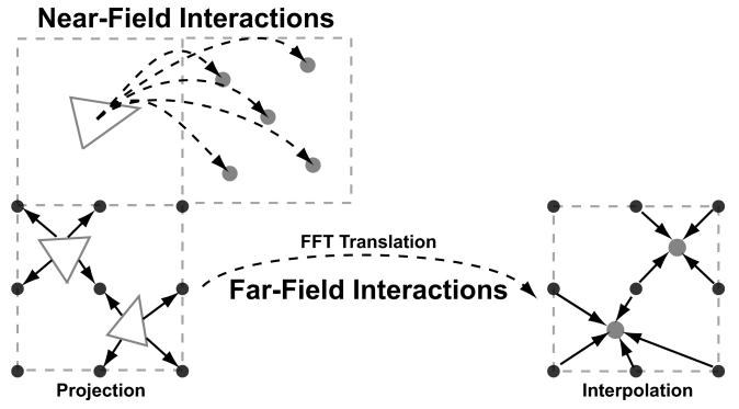
FFTSVD, like multipole methods, exploits the smooth decay of the Green's functions as the distance between source and evaluation point increases. Both types of methods use a spatial decomposition of the set of boundary elements to separate near-field interactions, which are computed exactly, from far-field or long-range interactions, which can be accurately approximated. The long-range interactions are approximated by projecting the dominant element source distributions, computed using an approximate singular value decomposition (SVD), onto a grid. Grid–grid interactions are computed via the fast Fourier transform (FFT), and the dominant responses are interpolated back to the destination integral equation collocation points. An overview of the FFTSVD method is presented in Figure 5, and a fully detailed description of the algorithm can be found in reference 43.
Figure 5.
An overview of the FFTSVD matrix compression algorithm. FFTSVD uses a multi-level octree spatial decomposition to separate element–evaluation point interactions into near- and far-field components at multiple length scales. When two cubes at the finest length scale are nearby, interactions are computed through direct integration. However, when two interacting cubes are well separated, dominant sources are projected onto a cubic grid and translated to a grid surrounding the recipient cube. The FFT is used to accelerate this translation operation. Finally, the grid potentials can be interpolated back onto the dominant responses of the element centroids. This Figure has been adapted from reference 43.
For the general multi-boundary Green's theorem formulation, each node in the tree contains an FFTSVD-compressed operator that simultaneously stores both the single- and double-layer interactions between all elements that bound the region.
Preconditioning
It has been previously noted in the literature that the non-derivative Green's theorem formulation can lead to ill-conditioned systems of linear equations, especially with decreasing boundary-element size [32]. To address this issue, we have implemented preconditioning in order to efficiently solve these systems with iterative methods. By definition, a preconditioner is any matrix P such that the equation PAx = Pb has better convergence properties than the original system Ax = b when the systems are solved iteratively. In general, Krylov iterative methods are most efficient at solving linear systems with clustered eigenvalues [76]. Because the identity matrix I (or multiples) has an optimal clustering, P is generally selected such that P ≈ A−1 but is inexpensive to form and apply.
For the discretized integral operator matrices that arise from the Green's theorem formulation, the dominant entries tend to be the self-influence terms, for which the evaluation point is on the element over which the integral is performed. Consequently, a reasonable choice for P is the inverse of a sparse matrix that contains only these self-term entries. As an examination of Equations 18, 30, and 31 should make clear, the sparse matrix that includes just the self-influence terms is not diagonal, but no row has more than two non-zero off-diagonals. We call such a matrix block-diagonal because it possesses 2×2 diagonal block structure and each block is diagonal. Here, P can be easily applied using the LU-factorization of this block diagonal matrix because the factors have the same sparsity pattern as the original matrix.
Curved element discretization
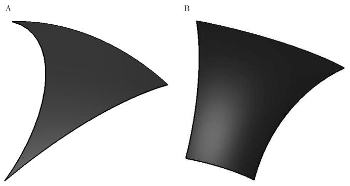
In order to generate the basis functions used in the boundary-element method, we discretize the molecular and accessible surfaces that define the problem into curved elements that can exactly represent the underlying geometry [40]. Accessible surfaces [45], also called expanded van der Waals surfaces, are generally used to model the ion-exclusion layer and can be completely described by convex spherical patches bounded by circular arcs. These circular arcs are not necessarily geodesic arcs, and thus we use the concept of a generalized spherical triangle (GST) (Figure 6A) [39, 40]. A GST is a three-sided curved element that lies on the surface of a sphere, where each edge is a portion of a circular arc. If the arc center for all three edges happens to be the center of the sphere, a traditional spherical triangle is recovered. A spherical patch can be discretized into a set of GSTs by starting with a flat element triangulation, and then assigning the appropriate circular arc to each element edge. Typically, edges that lie along the interface between atoms are assigned non-geodesic arcs that follow the curve of intersection, while all other edges are assigned geodesic arcs. However, the generation of topologically valid GST discretizations from flat elements is challenging, and one technique for achieving this is presented in [40].
Figure 6.
The two types of curved elements used to discretize accessible and molecular surfaces. A generalized spherical triangle (GST) (A), is a three-sided region on the surface of a sphere bounded by three circular arcs. These arcs are not necessarily geodesic arcs. Torus patches on molecular surfaces are discretized using toroidal elements (B), which are isomorphic to a rectangle.
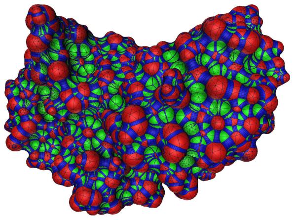
Molecular surfaces [38,46,48], used here to model dielectric interfaces, are the surfaces of closest approach for the surface of a probe sphere that is rolled over a molecule. They can be described using three types of surface patches [38]. Convex spherical patches are defined where the probe sphere is in contact with only one atom, and can be described by portions of a sphere bounded by circular arcs and discretized with GSTs. Concave spherical re-entrant patches are formed when the probe touches three or more atoms simultaneously, and are also described by GSTs. When the probe simultaneously touches two atoms, a portion of a torus is generated. Toroidal regions are discretized into four-sided curved torus elements (Figure 6B) that are isomorphic to a rectangle. A fully meshed curved element discretization for the barnase–barstar complex molecular surface is shown in Figure 7.
Figure 7.
A rendering of a curved element discretization for the molecular surface of the barnase–barstar protein complex. Red regions indicate convex spherical patches, green regions are re-entrant spherical patches, and blue regions are re-entrant toroidal patches. Black lines indicate the boundaries between elements. The graphic depicts an approximation to the discretized geometry used for calculation. Every GST and torus element has been approximated by a very large number of flat triangles for the purpose of visualization only, and the true surface normal in conjunction with Phong shading have been used to render the image. Surface patches with higher curved element densities were regions where finer discretization was necessary to exactly represent the molecular geometry.
Techniques for integrating singular Green's functions over these curved GST and torus elements have been developed, and are discussed in detail in [40]. Briefly, when the evaluation point in the integrand is far away from the element, low-order quadrature rules are used to perform numerical integration. These quadrature rules are generated by creating a smooth mapping between a reference flat triangle or rectangle (for GSTs and torus elements, respectively) that relates a known quadrature rule on these simple domains [77] to those applicable on the curved elements. When the evaluation point is near or on the curved element, even high-order quadrature rules are not sufficient to capture the singularity. As a result, we adopt specialized methods for each element type and Green's function. For the single-layer Laplace (Poisson) kernel, we integrate over GSTs using a technique that reproduces the effect of element curvature using a higher-order distribution on a reference flat triangle [78]. Single-layer Laplace integrals over torus elements are evaluated using an element-splitting approach, which avoids integration near the singularity using recursive subdivision. Details of the subdivision procedure can be found in reference 40. When integrating the double-layer Laplace kernel in the near-field over both GST and torus elements, we exploit the fact that the double-layer potential is equal to the solid angle subtended by the curved element when observed from the evaluation point [49, 79]. In order to integrate the linearized Poisson–Boltzmann kernel or its normal derivative in the near field, we adopt a previously presented desingularization technique [32]. This method divides the integral into a singular Laplace component that can be integrated as described above, and a smooth component that can be integrated using quadrature.
Computational details
Peptide and protein structure preparation
The structure of a peptide derived from an HIV-1 protease cleavage site was obtained from the Protein Data Bank (PDB) with accession code 1F7A [67]. This structure contains nine visible residues of a decameric peptide bound to an inactivated mutant of HIV-1 protease; only the peptide was considered in further calculations. An N-terminal acetyl blocking group and a C-terminal methylamide blocking group were added to the peptide. The wild-type structure for the barnase–barstar protein complex was also obtained from the PDB as accession code 1BRS [68]. To prepare this structure for calculation, we followed a previous protocol [80] where all but a set of 12 interfacial water molecules were removed. These water molecules were associated with barnase in all binding calculations. For both the peptide and barnase–barstar structures, hydrogen atoms were added using the hbuild module [81] in the charmm computer program [82] using the param22 parameter set [83] and a distance-dependent dielectric constant of 4. In addition, side-chain atoms that were missing from the crystal structures were rebuilt using charmm and the default param22 geometry. All ionizable residues were left in their standard states at pH 7, with histidine side chains left neutral and protonated on the ε nitrogen.
Modeling of barnase–barstar mutations
Three point mutations (E73Q in barnase, D39A in barstar, and T42A in barstar) were built into the barnase–barstar complex for subsequent analysis. The alanine mutations were created by cutting back the wild-type residue to the β-carbon. The E73Q mutation was built by sampling glutamine side-chain dihedral angles in 30-degree increments using charmm [82] and the param22 parameter set [83]. For each sampled conformation, the side chain was energy minimized until convergence keeping all other atoms in the structure fixed. The lowest-energy minimized geometry was taken to represent the E73Q mutation. The selected rotamer for the E73Q mutation utilized the same χ1 and χ2 angles as the crystallographic E73 residue, but the χ3 angle differed by approximately 30 degrees.
BEM and FFTSVD parameters
Parameters used in the FFTSVD algorithm [43] included a drop tolerance of 10−5 for SVD compression, spatial decomposition until each cube contained no more than 32 elements, and a grid size of 4 × 4 × 4 in each finest-level cube to represent dominant sources and responses during FFT translation. The boundary-element matrix equations were solved using the Krylov subspace method GMRES [52] to a relative residual of 10−6. All curved BEM calculations were performed on a machine with two dual-core 2.0-GHz Opteron processors running a parallel version of the FFTSVD library. All presented timings are the sum of CPU usage across all four cores.
Finite-difference solver and parameters
In order to compare our curved boundary-element solver to finite-difference methods (FDM), we have independently implemented a FDM solver using previously described methods [10]. This implementation uses successive over-relaxation (SOR) with an optimized acceleration factor to solve the finite-difference equations to a relative residual of 10−6. An analytical molecular surface representation was used to assign dielectric constants to the finite-difference grid. In order to address truncation of the boundary condition at infinity, a focusing scheme [9] was employed in all FDM calculations where the molecule of interest occupied first 23% and then 92% of the finite-difference grid. For the low-percent fill run, a Debye–Hückel screened potential in solvent dielectric was used to assign potentials to the boundary of the cubic grid. For the high-percent fill run, boundary potentials were taken by interpolation from the low-percent fill solution. It is common to average results from multiple translations of the molecule relative to the grid in order to reduce error due to the grid representation [9]. Unless otherwise stated, here only one placement was used to compare to the curved BEM, which is insensitive to translations or rotations of the geometry. Cubic grids used to discretize molecular geometries in the FDM spanned 129 to 481 grid points per side in increments of 32, which are all solvable within 4 GB of computer memory. These sizes correspond to grid resolutions of approximately 2.3 to 8.6 grid points per ångström for the barnase–barstar complex. All FDM calculations were performed in serial on one core of a machine with two dual-core 2.0-GHz Opteron processors.
The use of multigrid approaches in finite-difference methods produces solutions of equal accuracy to SOR in less time while requiring only a slightly larger memory footprint [11,14]. Because the accuracy does not improve and memory is often limiting, we have chosen to compare to SOR here.
Electrostatic solvation and binding calculations
All continuum electrostatic calculations were performed using a molecular dielectric constant of 4, a solvent dielectric constant of 80, a molecular surface with probe radius 1.4 Å for dielectric interfaces, an accessible surface with probe radius 2.0 Å for ion-exclusion layers, and an ionic strength of 145 mM. To compute the solvation free energy of a molecule, we subtracted from the free energy of the solvated state that of a reference state, where the solvent dielectric constant was equal to the molecular dielectric constant and no salt was present. The BEM calculates this free energy difference directly, and an explicit reference state is not needed. In the FDM implementation, the energy of the reference state is explicitly computed to cancel grid energy.
For rigid-binding calculations, the electrostatic component of the free energy of binding was computed as the sum of Coulombic interactions (computed with the molecular dielectric constant) in the bound state and the differential solvation energy between the bound complex and infinitely separated individual binding partners. For the FDM, identical placement of each molecule on the grid was used to accelerate the calculation by canceling the grid energy in the complex with grid energies for the individual binding partners.
Non-rigid electrostatic binding energies were computed by first energy minimizing the geometry of the complex and each of the isolated binding partners separately. The minimization was performed using Charmm and the Param22 parameter set, relaxing all atoms with 1,000 steps of adapted basis Newton–Raphson (ABNR) minimization using a distance-dependent dielectric constant of 4. The binding energy was then computed using a thermodynamic cycle where the two isolated binding partners were first desolvated to a uniform medium with the molecular dielectric constant and no salt. In low-dielectric medium, the partners were deformed to their bound-state structures and then rigidly bound, computing all electrostatic changes with Coulomb's law in molecular dielectric. Finally, the complex was re-solvated. The sum of the energetic changes in these three steps was taken as the non-rigid electrostatic binding free energy. Due to the change in geometry between the bound and unbound states in non-rigid binding, the FDM grid energy cancellation technique could not be used to avoid low-dielectric simulations, and explicit reference states were employed for all FDM solvation calculations.
Generating curved element discretizations
Molecular and accessible surfaces were discretized into curved elements starting with high-quality flat triangular meshes for spherical regions from the program Netgen [84]. These elements were then converted, along with torus patches, to curved elements as described in reference 40. Curved-element discretizations for molecular geometries were generated such that memory requirements did not exceed 4 GB. For the sphere test case, discretizations were obtained between roughly 80 and 58,000 curved elements including ion-exclusion and dielectric interface surfaces. These element counts correspond to inverse average element edge lengths between approximately 0.1 and 1.6 Å −1. For the peptide example, element counts spanned approximately 5,200 to 128,000, and for the various barnase–barstar complexes, the span was roughly 92,000 to 310,000 total curved elements. These element counts correspond to inverse average element edge lengths between approximately 1.4 and 7.4 Å −1 for the peptide and between 2.1 and 4.5 ÅA−1 for barnase–barstar complexes.
Results and Discussion
For all calculations, we compared our boundary-element results to those generated using finite-difference methods. Although geometric measures can be defined for such comparisons [28,31], we chose to use computer resources, such as time and memory, as our primary metrics, to determine which method can achieve Rerior convergence properties for given resources. We could not guarantee that the geometry of the problem being solved was exactly the same in both methods because different algorithms were used to generate molecular boundaries. In principle, both algorithms compute with identical surfaces; however, implementation details can cause different surfaces to be returned, particularly when the surface possesses singularities or features too small to be represented given machine precision. Therefore, for systems without closed-form solutions, the level of convergence for a particular method was assessed solely on how little the solution changed as additional computer resources were expended.
Electrostatic solvation free energies
One of the simplest linearized Poisson–Boltzmann calculations is the computation of the electrostatic component of the free energy associated with the transfer of a molecule from low- to high-dielectric medium, where the high-dielectric region contains an ion-exclusion layer with salt outside. This quantity, known as the electrostatic solvation free energy, is useful in many calculations and forms the basis for computing more complex quantities such as electrostatic binding free energies. We first validated the multi-surface formulation by computing the solvation free energy for a simple spherical test case, which has a closed-form solution. Then, we gauged the accuracy of the solver by examining more complicated geometries including a peptide derived from an HIV-1 protease substrate site as well as the barnase–barstar protein–protein complex.
Protein-sized sphere with ion-exclusion layer
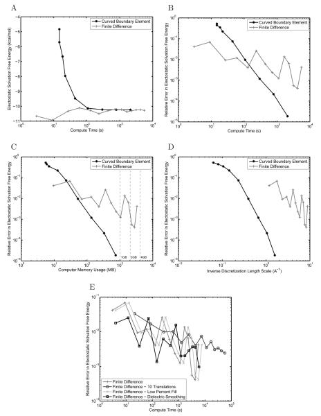
To test the correctness of the multiple surface formulation, the electrostatic solvation free energy for a protein-sized sphere of radius 20.0 Å with a charge of +1e placed 2.0 Å inside the surface was computed. An ion-exclusion layer was added 2.0 Å outside the sphere surface, creating a two-boundary problem. BEM and FDM solutions were compared to the analytical solvation free energy for this geometry [73] as displayed in the convergence plots shown in Figure 8. Relative errors are computed by the relation ‖Ecalculated − Eanalytical‖2/Eanalytical, and are therefore dimensionless.
Figure 8.
Convergence plots for the solvation free energy for a protein-sized sphere with a near-surface charge and ion-exclusion layer. Results are compared between the curved BEM and FDM implementations in terms of absolute electrostatic solvation free energy per unit compute time (A), relative error from the analytical solution per unit compute time (B), relative error per unit computer memory (C), and relative error per unit inverse discretization length scale (where the length scale is average mesh curved edge length for BEM and distance between grid points for FDM) (D). In addition the effect of several common improvements to the FDM on the relative error is shown (E). For (C), dashed lines have been added at 1 GB, 2 GB, and 4 GB of computer memory for convenience.
Although the BEM and FDM methods produced similar absolute electrostatic solvation free energies (Figure 8A), it is clear that in terms of relative error from the analytical solution (Figure 8B) that the curved BEM method is able to achieve Rerior accuracy given the same amount of compute time as the finite-difference method. For this problem, the FDM is limited to 2–3 digits of accuracy, even when using resolutions greater than 8 grid points per ångström. In terms of memory usage, the curved BEM also offers significant improvements over traditional FDM for the sphere (Figure 8C), allowing similar accuracy to be obtained while using an order of magnitude less memory.
Another metric commonly used to compare BEM and FDM is accuracy achieved given the characteristic length scale for the discretization used to solve the problem. In finite-difference methods, this length is generally taken to be the grid spacing, and in boundary-element methods, one common definition is the average edge length of the elements forming the mesh [31]. As shown in Figure 8D, the grid spacings used in the FDM are smaller than the average element edge length in the curved BEM, indicating that finer discretization scales in the FDM are still insufficient to provide similar accuracy to the curved BEM.
To verify that the curved BEM presented here does indeed offer improved accuracy over FDM approaches, we implemented from the literature several improvements to the FDM that have the potential to increase accuracy. Specifically, we considered translational averaging [9,85], where the solvation energies of multiple relative placements of the molecule on the grid are averaged. In addition, we examined a 3-stage focusing scheme where an additional 5.75% fill calculation was added to improve the representation of the far-field boundary condition. Finally, a previously described nine-point dielectric boundary smoothing scheme [86] was employed. As shown in Figure 8E, none of these alternatives have a significant impact on the computed energetics of the protein-sized sphere example.
Another popular improvement to FDM is the scaled surface charge method proposed by Honig and co-workers [15]. In this method, potentials at the atom centers are computed using induced surface charges on the molecular surface rather than using grid interpolation. We have found that this method offers improved accuracy for problems with zero ionic strength (data not shown), but it is currently not applicable to problems containing salt regions.
HIV-1 protease substrate peptide
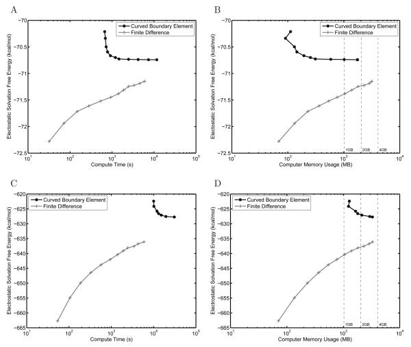
To evaluate the method on a more complex example, the electrostatic solvation free energy for a peptide derived from an HIV-1 protease substrate site was computed using BEM and FDM including salt and an ion-exclusion layer. The computed solvation free energy was plotted as a function of compute time (Figure 9A) or computer memory usage (Figure 9B). It is clear from examining Figure 9A that the solutions provided by the curved BEM implementation appear more converged than those obtained from the FDM. The solution at the finest discretization levels for the curved BEM are changing by as little as 10−3 kcal/mol given a 1.5-fold increase in the number of curved elements, while those from FDM are still changing on the order of tenths of kcal/mol when the grid resolution is improved by only 15%. In addition, the BEM compares favorably to FDM in terms of memory usage, allowing higher accuracy to be achieved with the same amount of storage.
Figure 9.
Computed solvation free energies, using curved BEM and FDM, for an HIV-1 protease substrate peptide (A, B) and the barnase–barstar complex (C, D). The absolute electrostatic solvation free energy is plotted as a function of compute time (A, C) or computer memory usage (B, D). In (B, D) dashed lines have been added at 1 GB, 2 GB, and 4 GB of computer memory for convenience. The slight decrease in memory usage with increasing refinement observed in B is an artifact of the spatial partitioning scheme used in the FFTSVD algorithm.
Barnase–barstar complex
To be competitive with finite-difference methods, the curved boundary-element method presented here must be able to achieve high accuracy per unit compute time on large macromolecules, where the number of curved elements required to discretize the geometry can be large. To test the solver on a moderately sized protein system, we computed the solvation free energy of the barnase–barstar protein complex [68, 87, 88], a model binding system for which electrostatic interactions have been shown to be important [80,88-92]. In addition to an ion-exclusion layer, the problem geometry included four continuum-solvent-filled cavities inside the main dielectric boundary. These cavities are holes in the protein structure large enough for a molecular-surface probe sphere to fit, and are treated as high-dielectric regions in both the curved BEM and FDM calculations. A comparison between the BEM and FDM for computing the absolute solvation free energy of this complex is shown in Figures 9C and 9D. Even the finest BEM and FDM discretizations that can be solved on a computer with 4 GB of memory give answers that differ by 8–9 kcal/mol out of more than 600 kcal/mol. Furthermore, it is difficult to establish whether the two methods will converge to the same answer, although there is no evidence that they will not. However, the curved BEM profile does appear to be relatively flat, even though the solution changed by approximately 0.2 kcal/mol between the two highest-resolution calculations, which suggests that it may be near convergence.
As can be seen in Figure 9C, even the coarsest BEM discretization obtained for the barnase–barstar complex requires more compute time than the finest discretization used for the FDM. The timings for the FDM remain relatively constant across the presented problems because they depend primarily on the grid size. In contrast, the BEM requires more curved elements to discretize a larger molecular surface, resulting in significantly increased simulation cost. However, this increased cost appears to be accompanied by improved convergence; achieving a similar level of convergence using FDM is theoretically possible but would require memory beyond that currently available in general-purpose workstations. In addition, previous work [40] demonstrated that ten-fold fewer curved elements are needed to achieve the same level of convergence as a flat element discretization, suggesting that flat BEM would also be unable to provide a similarly converged answer without dramatically increased memory costs.
The accuracy of the BEM scales with the element density; accordingly, the larger barnase–barstar complex cannot be discretized at the same fineness as was feasible for the peptide example. The BEM-calculation solvation energies in Figures 9A and 9C exhibit similar curvature, and the “knees” of the two curves are separated by approximately a factor of ten in compute time. This difference is expected considering the ratio of the surface areas for the peptide and barnase–barstar complex (952 Å2 and 8019 Å2, respectively). The level of FDM convergence might also be expected to suffer for larger problems due to decreasing grid resolution given the same number of grid points. Surprisingly, the FDM appeared to lose less relative accuracy with increasing problem size as compared to the BEM. For the peptide and barnase–barstar solvation energies, the highest resolution FDM calculations were still changing by approximately 0.05 and 0.5 kcal/mol respectively. In the curved BEM results, they were changing by 0.001 and 0.2 kcal/mol, indicating a larger fold loss in convergence.
Importance of preconditioning
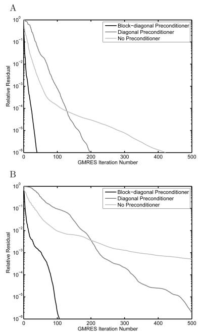
To demonstrate how effectively the block-diagonal preconditioner accelerates convergence of the iterative solution of the BEM equations, we repeated the solvation energy calculation for one discretization of the peptide example and one discretization of the barnase–barstar complex using several preconditioners. Specifically, we performed the calculation without preconditioning, with a purely diagonal preconditioner, and with the presented block-diagonal preconditioner. As shown in Figure 10, the number of GMRES iterations required to achieve a relative residual of 10−6 without preconditioning was 422 for the peptide and 1131 for the barnase–barstar complex. The purely diagonal preconditioner required 198 or 526 iterations, and the full block-diagonal preconditioner reduced this even further to 40 iterations for the peptide and 106 for the barnase–barstar complex. In general, the block-diagonal preconditioner allows even complex geometries to be solved to a relative residual of 10−6 in approximately 150 or fewer GMRES iterations.
Figure 10.
Comparison of preconditioning strategies when solving for the electrostatic solvation free energy of an HIV-1 protease substrate peptide discretized with 18,657 and 7,089 elements on the dielectric and ion-exclusion surfaces, respectively (A) or the barnase–barstar complex discretized with 61,493 and 28,800 elements (B). In both cases, the block-diagonal preconditioner significantly reduced the number of GMRES iterations required to solve the linear system of BEM equations to a relative residual of 10−6.
Rigid electrostatic binding free energies
Another useful quantity often calculated using the LPBE model is the rigid electrostatic binding free energy between a pair of interacting molecules — the electrostatic free energy difference between infinitely separated binding partners and the bound complex with no change in conformation. One component of this quantity is the difference in solvation energy between the bound state and the two unbound states. This differential electrostatic solvation is added to the direct Coulombic interactions made between the partners in the bound state. To measure the role that LPBE solver accuracy plays in this class of calculations, as well as to compare the curved BEM to FDM, we computed the rigid electrostatic binding free energies for the wild-type barnase–barstar complex and three experimentally characterized single mutants (E73Q in barnase; T42A and D39A in barstar) [88,93,94] that have been previously shown to have a significant effect on electrostatic binding calculations [89, 95-97]. These mutations were built into the wild-type barnase–barstar complex with minimal perturbation, where all atoms remained in the same position except at the site of mutation.
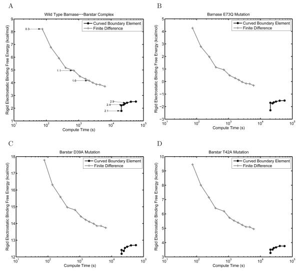
The results of these rigid electrostatic binding calculations are shown in Figure 11. For the wild-type barnase–barstar structure as well as the mutant complexes, the BEM calculations showed smaller changes in the computed energies with increasing problem discretization. In addition, the FDM appears to converge towards the BEM solution, with FDM rigid-binding free energies underestimated by 1-2 kcal/mol. Given the decreasing effect of FDM grid resolution on improving accuracy, significantly finer discretizations would be required for the FDM to achieve a similar solution to the curved BEM.
Figure 11.
Comparison between curved BEM and FDM for computing the electrostatic component of the rigid binding free energy between the wild-type barnase–barstar complex (A), and three mutant complexes, E73Q in barnase (B), D39A in barstar (C), and T42A in barstar (D). The binding free energy obtained is plotted as a function of the compute time required. In (A), several FDM and BEM results are labeled with their inverse discretization length scale in ångströms−1 (inverse grid spacing or inverse average curved element edge length, respectively).
Differential rigid electrostatic binding free energies between mutants and wild type
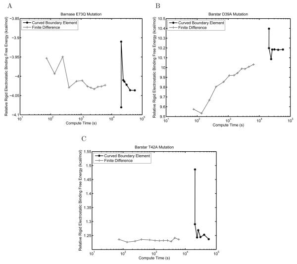
Often, when comparing a set of protein mutations to identify those with improved electrostatic properties, one is more interested in the relative electrostatic rigid binding free energies compared to wild type than in the absolute binding free energies themselves. To gauge the effect of solver accuracy on relative binding free energies, we calculated the difference in rigid electrostatic binding free energy between each mutant and the wild type at every level of problem discretization (Figure 12).
Figure 12.
Comparison between curved BEM and FDM for computing relative rigid electro-static binding energies between mutant and wild-type barnase–barstar complexes. Results are shown for the mutations E73Q in barnase (A), D39A in barstar (B), and T42A in barstar (C). The relative binding free energy is plotted as a function of the compute time for the mutant complex rigid binding free energy.
For all mutants studied, both methods appear to be converged to tenths of kcal/mol or better, and give very similar relative binding energies. Low discretizations of the FDM provide solutions very close to the final answer in a very short amount of time. This may be due to error cancellation because the mutant structures differ little from the wild type; mutant and wild-type structures were placed identically on the grid, which should facilitate error cancellation. For problems in which electrostatic energies are being compared between structures for which most atoms are located at identical positions, finite-difference methods may be particularly well suited. Minimal-perturbation relative-binding calculations are often used when making predictions to improve protein binding or stability, especially in the field of computational protein design [71, 98-101].
Non-rigid electrostatic binding free energies
The rigid binding model, although a useful approximation, is deficient in that it does not allow structural relaxation between the bound and unbound states. In contrast, non-rigid binding calculations allow the two binding partners to adopt lower-energy conformations in their unbound states that are different from their geometry in the bound complex. Accounting for this relaxation is important because the energetic costs associated with adopting the bound-state conformation contribute to experimentally determined binding free energies. Consequently, a variety of methods have been presented in the literature for treating non-rigid effects in protein–protein binding using continuum electrostatics [102-104]. For example, in the Molecular Mechanics – Poisson-Boltzmann Surface Area (MM-PBSA) methodology [102,103], snapshots of bound-state geometries are taken from explicit-water molecular dynamics simulations. The electrostatic free energies associated with these snapshots are calculated by removing the water molecules and using continuum electrostatic calculations to estimate the solvation free energy for each independent solute configuration. The ensemble averages over the snapshots can then be used to estimate the free energies associated with molecular events such as binding. One feature these non-rigid binding techniques share is that there is no longer a direct correspondence between the majority of relative atomic positions in the bound and unbound states. As a result, we hypothesized that the FDM would no longer be able to take advantage of cancellation of error when computing non-rigid binding effects and that the accuracy of the overall calculation would depend strongly on the ability to independently converge the solvation free energy for each state. To test this idea, we implemented an approximation to the MM-PBSA scheme involving independent minimization of the complex and unbound binding partners and a thermodynamic cycle to compute electrostatic free energies [104]. The non-rigid electrostatic binding free energies for mutants were subtracted from those for the wild-type barnase–barstar complex to generate non-rigid relative binding free energies.
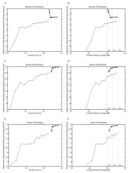
As shown in Figure 13, the curved BEM method regains an accuracy advantage in non-rigid binding calculations. The curves in this plot resemble those from absolute binding free energy calculations (Figure 11). The finite-difference solution does not appear to be well converged at low resolution and seems to gradually approach the boundary-element solution. Although in some cases it appears there may be systematic differences in the solutions provided by FDM and BEM, it is important to note that in the FDM, the error is proportional to the grid spacing squared while compute time increases as the grid size cubed. Therefore, increasing the grid size significantly increases computational expense and memory use, but offers diminishing returns in improved accuracy.
Figure 13.
Comparison between curved BEM and FDM for computing relative non-rigid electrostatic binding energies between mutant and wild-type barnase–barstar complexes. Results are shown for the mutations E73Q in barnase (A,B), D39A in barstar (C,D), and T42A in barstar (E,F). The relative binding free energy is plotted as a function of compute time (A,C,E) or computer memory usage (B,D,F) when calculating the mutant complex non-rigid binding free energy. In (B,D,F), dashed lines have been added at 1 GB, 2 GB, and 4 GB of computer memory for convenience.
Because grid cancellation could not be exploited in non-rigid binding to avoid reference state calculations in the FDM, we computed the solvation of each state independently allowing the protein complex or binding partners to fill the entire finite-difference grid. Therefore, when subtracting the solvation energies of binding partners from the bound complex, we were subtracting calculations solved at very different grid resolutions. To determine if this was responsible for the inability of FDM to converge relative non-rigid electrostatic binding energies, we repeated the calculation using fixed grid placement to ensure that the solvation energy of each state was computed at roughly the same number of grid points per ångström. However, this modification did not improve the ability of FDM to converge relative non-rigid binding energies (data not shown).
Multiple electrostatic solves for the same problem geometry
As shown above, the curved BEM, although offering better convergence properties, can be time consuming on large geometries. Currently, the dominant computational cost in our implementation is compressing the integral operators using the FFTSVD algorithm, which primarily involves computing costly integrals over nearby curved elements. In contrast, the FDM requires very little time to initialize the system of linear equations and spends almost all compute time solving them. There exist several types of useful electrostatic calculations that involve multiple simulations of the same problem geometry; for these problems, the expensive BEM “setup” time can be amortized over all calculations.
One such example is charge optimization [72, 73, 80, 105-107], which determines the optimal partial atomic charges for a ligand that minimize the electrostatic component of its binding free energy with a receptor molecule. In charge optimization, two geometries for the ligand are considered: the bound state, where it is complexed with the receptor molecule, and the unbound state, where it is isolated in solution. Each ligand charge is set to +1e independently, leaving all others at zero, and one determines the difference in solvation potential at the ligand charge locations between the bound and unbound states by solving the LPBE twice. This produces the ligand desolvation matrix, an important component of the charge optimization equation [72, 73]. Overall, 2n solves of the LPBE are required, where n is the number of atoms in the ligand. When using the BEM, each state's integral operator only needs to be compressed once, and the compressed operator can be used to solve the n right-hand sides that only depend on the atomic charges.
To compare the performance of the curved BEM and FDM on a charge optimization problem, we computed the ligand desolvation matrix for barstar in the wild-type barnase–barstar complex. In total, 1403 simulations were performed in each of the bound and unbound states (2806 total). In Table 1 we report the time required to compute the ligand desolvation matrix for three discretization levels of the finite-difference and curved boundary-element methods. The inverse length scales in Table 1 may be compared to the labeled points on the absolute binding free energy plot shown in Figure 11A.
Table 1.
Compute time required to calculate the entries of the ligand desolvation matrix for barstar in the wild-type barnase–barstar complex (2806 independent PB solves). For both the curved BEM and FDM, the calculation was repeated at three discretization levels. For the curved BEM, the inverse average curved element edge length reported is for all surfaces in the bound state geometry. Normalized timings are relative to a single complete solve of the bound-state geometry.
| Method | |||
|---|---|---|---|
| Inverse Grid Spacing (Å−1) |
Time (s) | Normalized Timing to 1 PB Solve |
|
| FDM | 0.3 | 4.2 × 10⁴ | 2806 |
| 1.1 | 6.3 × 10⁵ | 2806 | |
| 1.6 | 1.8 × 10⁶ | 2806 | |
|
| |||
| Inverse Average Curved Element Edge Length (Å−1) |
Time (s) | Normalized Timing to 1 PB Solve |
|
|
|
|||
| Curved BEM | 2.1 | 7.6 × 10⁵ | 279 |
| 2.4 | 1.3 × 10⁶ | 414 | |
| 2.9 | 2.0 × 10⁶ | 495 | |
For the finer discretization BEM calculations, the compute time was comparable to that required for the finer FDM discretizations. Relating these discretization levels to the convergence plot suggests that for these multiple-solve problems, the BEM may offer superior accuracy for similar computational cost. Normalized timings demonstrate that the curved BEM method can calulate the ligand desolvation matrix in significantly less time than 2n independent PBE solves due to amortization of the cost of initializing and compressing the matrix operators.
In addition to charge optimization, electrostatic component analysis [69-71], which examines the contribution of independently charged groups of atoms to electrostatic binding or stability, also requires multiple solves of the same problem geometry. It is expected that similar performance improvements should be seen for these calculations as well.
Summary
In conclusion, we have presented an implementation of the boundary-element method for linearized Poisson–Boltzmann continuum electrostatics that is capable of achieving high accuracy and solving the same topologies of homogeneous dielectrics, point charges, and salt regions that volume-based methods are capable of solving. The goal of high accuracy has been achieved via the synthesis of several enabling technologies. These included a general Green's theorem integral formulation for multiple embedded regions, curved-element discretization with robust integration methods, and preconditioned Krylov subspace methods combined with matrix compression using the FFTSVD algorithm. Solutions may now be converged to high precision (tenths of kcal/mol) even for protein geometries, with reasonable computer resources such as a workstation with 4 GB of memory and two or four processors. Although such requirements are somewhat higher than commonly found on the desktop at the present time, future work may identify improvements to reduce time and memory use. In particular, the representation of surface variables with higher-order basis functions is an appealing approach that warrants further study. Additionally, the ability to accurately model multiple embedded regions of homogeneous dielectric permits the use of more than one dielectric constant to represent the protein interior, allowing for more complex models of protein polarizability to be explored [62, 108-111].
Comparing the performance of the curved BEM against a reference finite-difference solver identified types of calculations for which improved accuracy may be important. For example, when computing absolute electrostatic solvation free energies or the electrostatic component of rigid binding energies, the curved BEM method offers superior convergence properties. Even at the highest discretizations possible within 4 GB of computer memory, finite-difference methods did not appear to be converged, as the solutions continued to change significantly with increased expenditure of computing resources. However, when comparing differential rigid binding energies between mutant and wild-type protein complexes, even coarse finite-difference simulations sufficed to capture relative effects. This is not surprising considering that the local structural perturbations allow for cancellation of error. Relative rigid binding calculations with local geometry perturbations are prevalent in ranking the results of molecular design efforts, and finite-difference methods are an attractive tool for this class of computation. However, when non-rigid effects were introduced into the binding model, and the bound and unbound states were allowed to relax independently, finite-difference methods performed much less well. Therefore, as more sophisticated non-rigid models of binding are employed in ranking results of molecular design calculations, higher-accuracy LPBE solvers such as the presented curved BEM may become necessary to make reliable predictions.
Acknowledgements
This work was partially supported by the National Institute of General Medical Sciences of the NIH (GM065418 and GM066524), the Singapore-MIT Alliance, and the MARCO Interconnect Focus Center. J. P. Bardhan gratefully acknowledges the support of a Department of Energy Computational Science Graduate Fellowship.
References
- 1.Honig B, Nicholls A. Science. 1995;268:1144–1149. doi: 10.1126/science.7761829. [DOI] [PubMed] [Google Scholar]
- 2.Sharp KA, Honig B. Ann. Rev. Biophys. Biophys. Chem. 1990;19:301–332. doi: 10.1146/annurev.bb.19.060190.001505. [DOI] [PubMed] [Google Scholar]
- 3.Davis ME, McCammon JA. Chem. Rev. 1990;90:509–521. [Google Scholar]
- 4.Roux B, Simonson T. Biophys. Chem. 1999;78:1–20. doi: 10.1016/s0301-4622(98)00226-9. [DOI] [PubMed] [Google Scholar]
- 5.Simonson T. Curr. Opin. Struct. Biol. 2001;11:243–252. doi: 10.1016/s0959-440x(00)00197-4. [DOI] [PubMed] [Google Scholar]
- 6.Baker NA. Meth. Enzymol. 2004;383:94–118. doi: 10.1016/S0076-6879(04)83005-2. [DOI] [PubMed] [Google Scholar]
- 7.Stakgold I. Green's Functions and Boundary Value Problems. 2nd John Wiley & Sons; 1998. [Google Scholar]
- 8.Gilson MK, Honig B. Proteins. 1988;4:7–18. doi: 10.1002/prot.340040104. [DOI] [PubMed] [Google Scholar]
- 9.Gilson MK, Sharp KA, Honig BH. J. Comput. Chem. 1988;9:327–335. [Google Scholar]
- 10.Nicholls A, Honig B. J. Comput. Chem. 1991;12:435–445. [Google Scholar]
- 11.Holst M, Saied F. J. Comput. Chem. 1993;14:105–113. [Google Scholar]
- 12.Madura JD, Briggs JM, Wade RC, Davis ME, Luty BA, Ilin A, Antosiewicz J, Gilson MK, Bagheri B, Scott LR, McCammon JA. Comput. Phys. Comm. 1995;91:57–95. [Google Scholar]
- 13.Rocchia W, Alexov E, Honig B. J. Phys. Chem. B. 2001;105:6507–6514. [Google Scholar]
- 14.Baker NA, Sept D, Joseph S, Holst MJ, McCammon JA. Proc. Natl. Acad. Sci. U.S.A. 2001;98:10037–10041. doi: 10.1073/pnas.181342398. [DOI] [PMC free article] [PubMed] [Google Scholar]
- 15.Rocchia W, Sridharan S, Nicholls A, Alexov E, Chiabrera A, Honig B. J. Comput. Chem. 2002;23:128–137. doi: 10.1002/jcc.1161. [DOI] [PubMed] [Google Scholar]
- 16.Sayyed-Ahmad A, Tuncay K, Ortoleva PJ. J. Comput. Chem. 2004;25(8):1068–1074. doi: 10.1002/jcc.20039. [DOI] [PubMed] [Google Scholar]
- 17.You TJ, Harvey SC. J. Comput. Chem. 1993;14:484–501. [Google Scholar]
- 18.Cortis CM, Friesner RA. J. Comput. Chem. 1997;18:1570–1590. [Google Scholar]
- 19.Cortis CM, Friesner RA. J. Comput. Chem. 1997;18:1591–1608. [Google Scholar]
- 20.Bowen WR, Sharif AO. J. Colloid Interface Sci. 1997;187(2):363–374. doi: 10.1006/jcis.1996.4705. [DOI] [PubMed] [Google Scholar]
- 21.Holst M, Baker N, Wang F. J. Comput. Chem. 2000;21:1319–1342. [Google Scholar]
- 22.Baker N, Holst M, Wang F. J. Comput. Chem. 2000;21:1343–1352. [Google Scholar]
- 23.Zauhar RJ, Morgan RS. J. Mol. Biol. 1985;186:815–820. doi: 10.1016/0022-2836(85)90399-7. [DOI] [PubMed] [Google Scholar]
- 24.Zauhar RJ, Morgan RS. J. Comput. Chem. 1988;9:171–187. [Google Scholar]
- 25.Zauhar RJ, Morgan RS. J. Comput. Chem. 1990;11:603–622. [Google Scholar]
- 26.Juffer AH, Botta EFF, Vankeulen BAM, Vanderploeg A, Berendsen HJC. J. Comput. Phys. 1991;97:144–171. [Google Scholar]
- 27.Zhou HX. Biophys. J. 1993;65:955–963. doi: 10.1016/S0006-3495(93)81094-4. [DOI] [PMC free article] [PubMed] [Google Scholar]
- 28.Bharadwaj R, Windemuth A, Sridharan S, Honig B, Nicholls A. J. Comput. Chem. 1995;16:898–913. [Google Scholar]
- 29.Purisima EO, Nilar SH. J. Comput. Chem. 1995;16:681–689. [Google Scholar]
- 30.Zauhar RJ, Varnek A. J. Comput. Chem. 1996;17:864–877. [Google Scholar]
- 31.Vorobjev YN, Scheraga HA. J. Comput. Chem. 1997;18:569–583. [Google Scholar]
- 32.Boschitsch AH, Fenley MO, Zhou HX. J. Phys. Chem. B. 2002;106:2741–2754. [Google Scholar]
- 33.Bordner AJ, Huber GA. J. Comput. Chem. 2003;24:353–367. doi: 10.1002/jcc.10195. [DOI] [PubMed] [Google Scholar]
- 34.Chipman DM. J. Chem. Phys. 2004;120:5566–5575. doi: 10.1063/1.1648632. [DOI] [PubMed] [Google Scholar]
- 35.Lu BZ, Zhang DQ, McCammon JA. J. Chem. Phys. 2005;122 doi: 10.1063/1.1924448. [DOI] [PubMed] [Google Scholar]
- 36.Lu BZ, Cheng XL, Huang JF, McCammon JA. Proc. Natl. Acad. Sci. U.S.A. 2006;103:19314–19319. doi: 10.1073/pnas.0605166103. [DOI] [PMC free article] [PubMed] [Google Scholar]
- 37.Atkinson KE. The Numerical Solution of Integral Equations of the Second Kind. Cambridge University Press; 1997. [Google Scholar]
- 38.Connolly ML. J. Appl. Cryst. 1983;16:548–558. [Google Scholar]
- 39.Zauhar RJ. J. Comput. Aid. Mol. Des. 1995;9:149–159. doi: 10.1007/BF00124405. [DOI] [PubMed] [Google Scholar]
- 40.Bardhan JP, Altman MD, Willis DJ, Lippow SM, Tidor B, White JK. J. Chem. Phys. 2007;127:14701–14718. doi: 10.1063/1.2743423. [DOI] [PMC free article] [PubMed] [Google Scholar]
- 41.Kuo SS, Altman MD, Bardhan JP, Tidor B, White JK. International Conference on Computer Aided Design (ICCAD) 2002 [Google Scholar]
- 42.Bardhan JP, Altman MD, Lippow SM, Tidor B, White JK. In Modeling and Simulation of Microsystems (MSM) 2005;1:512–515. [Google Scholar]
- 43.Altman MD, Bardhan JP, Tidor B, White JK. IEEE T. Comput. Aid. D. 2006;25:274–284. [Google Scholar]
- 44.Liang J, Subramaniam S. Biophys. J. 1997;73:1830–1841. doi: 10.1016/S0006-3495(97)78213-4. [DOI] [PMC free article] [PubMed] [Google Scholar]
- 45.Lee B, Richards FM. J. Mol. Biol. 1971;55:379–400. doi: 10.1016/0022-2836(71)90324-x. [DOI] [PubMed] [Google Scholar]
- 46.Richards FM. Ann. Rev. Biophys. Bioeng. 1977;6:151–176. doi: 10.1146/annurev.bb.06.060177.001055. [DOI] [PubMed] [Google Scholar]
- 47.Bajaj C, Lee HY, Merkert R, Pascuci V. In Proceedings of the Fourth Symposium on Solid Modeling and Applications. 1997:217–228. [Google Scholar]
- 48.Connolly ML. Science. 1983;221:709–713. doi: 10.1126/science.6879170. [DOI] [PubMed] [Google Scholar]
- 49.Jackson JD. Classical Electrodynamics. 3rd Wiley; 1998. [Google Scholar]
- 50.Ong ET, Lee KH, Lim KM. J. Micromech. Microeng. 2003;13:482–490. [Google Scholar]
- 51.Ong ET, Lim KM. Eng. Anal. Bound. Elem. 2005;29:175–189. [Google Scholar]
- 52.Saad Y, Schultz MH. SIAM J. Sci. Stat. Comput. 1986;7:856–869. [Google Scholar]
- 53.Nabors K, White J. IEEE T. Comput. Aid. D. 1991;10:1447–1459. [Google Scholar]
- 54.Greengard L, Rokhlin V. J. Comput. Phys. 1987;73:325–348. [Google Scholar]
- 55.Greengard L, Rokhlin V. Acta Num. 1997:229–269. [Google Scholar]
- 56.Boschitsch AH, Fenley MO, Olson WK. J. Comput. Phys. 1999;151:212–241. [Google Scholar]
- 57.Cheng H, Greengard L, Rokhlin V. J. Comput. Phys. 1999;155:468–498. [Google Scholar]
- 58.Ying LX, Biros G, Zorin D. J. Comput. Phys. 2004;196:591–626. [Google Scholar]
- 59.Hess JL, Smith AMO. J. Ship Res. 1962;8:22–44. [Google Scholar]
- 60.Newman JN. J. Eng. Math. 1986;20:113–126. [Google Scholar]
- 61.Cools R, Laurie D, Pluym L. ACM Trans. Math. Softw. 1997;23:1–15. [Google Scholar]
- 62.Hofinger S, Simonson T. J. Comput. Chem. 2001;22:290–305. [Google Scholar]
- 63.Bockris JO, Reddy AKN. Modern Electrochemistry: An Introduction to an Interdisciplinary Area. Plenum Press; 1973. [Google Scholar]
- 64.Im W, Beglov D, Roux B. Comput. Phys. Commun. 1998;111:59–75. [Google Scholar]
- 65.Grant JA, Pickup BT, Nicholls A. J. Comput. Chem. 2001;22:608–640. [Google Scholar]
- 66.Boschitsch AH, Fenley MO. J. Comput. Chem. 2004;25:935–955. doi: 10.1002/jcc.20000. [DOI] [PubMed] [Google Scholar]
- 67.Prabu-Jeyabalan M, Nalivaika E, Schiffer CA. J. Mol. Biol. 2000;301:1207–1220. doi: 10.1006/jmbi.2000.4018. [DOI] [PubMed] [Google Scholar]
- 68.Buckle AM, Schreiber G, Fersht AR. Biochemistry. 1994;33:8878–8889. doi: 10.1021/bi00196a004. [DOI] [PubMed] [Google Scholar]
- 69.Hendsch ZS, Tidor B. Protein Sci. 1999;8:1381–1392. doi: 10.1110/ps.8.7.1381. [DOI] [PMC free article] [PubMed] [Google Scholar]
- 70.Spector S, Wang MH, Carp SA, Robblee J, Hendsch ZS, Fairman R, Tidor B, Raleigh DP. Biochemistry. 2000;39:872–879. doi: 10.1021/bi992091m. [DOI] [PubMed] [Google Scholar]
- 71.Green DF, Tidor B. Proteins. 2005;60:644–657. doi: 10.1002/prot.20540. [DOI] [PubMed] [Google Scholar]
- 72.Lee LP, Tidor B. J. Chem. Phys. 1997;106:8681–8690. [Google Scholar]
- 73.Kangas E, Tidor B. J. Chem. Phys. 1998;109:7522–7545. [Google Scholar]
- 74.Yoon BJ, Lenhoff AM. J. Comput. Chem. 1990;11:1080–1086. [Google Scholar]
- 75.Kress R. Linear Integral Equations, Springer–Verlag. (2nd) 1999 [Google Scholar]
- 76.Golub GH, Loan CFV. Matrix Computations. The Johns Hopkins University Press; 1983. [Google Scholar]
- 77.Stroud A. Approximate Calculation of Multiple Integrals. Prentice Hall; 1971. [Google Scholar]
- 78.Wang X, Newman JN, White JK. Technical Proceedings of the 2000 International Conference on Modeling and Simulation of Microsystems. Nano Science and Technology Institute; 2000. pp. 473–476. [Google Scholar]
- 79.Willis DJ, Peraire J, White JK. 44th AIAA Aerospace Sciences Meeting, AIAA-2006-1253; 2006. [Google Scholar]
- 80.Lee LP, Tidor B. Protein Sci. 2001;10:362–377. doi: 10.1110/ps.40001. [DOI] [PMC free article] [PubMed] [Google Scholar]
- 81.Brünger AT, Karplus M. Proteins. 1988;4:148–156. doi: 10.1002/prot.340040208. [DOI] [PubMed] [Google Scholar]
- 82.Brooks BR, Bruccoleri RE, Olafson BD, States DJ, Swaminathan S, Karplus M. J. Comput. Chem. 1983;4:187–217. [Google Scholar]
- 83.MacKerell AD, Jr., Bashford D, Bellott M, Dunbrack RL, Evanseck JD, Field MJ, Fischer S, Gao J, Guo H, Ha S, Joseph-McCarthy D, Kuchnir L, Kuczera K, Lau FTK, Mattos C, Michnick S, Ngo T, Nguyen DT, Prodhom B, R. WE, III, Roux B, Schlenkrich M, Smith JC, Stote R, Straub J, Watanabe M, Wiorkiewicz-Kuczera J, Yin D, Karplus M. J. Phys. Chem. B. 1998;102:3586–3616. doi: 10.1021/jp973084f. [DOI] [PubMed] [Google Scholar]
- 84.Schöberl J. Comput. Visual. Sci. 1997;1:42–52. [Google Scholar]
- 85.Shen J, Wendoloski J. J. Comput. Chem. 1996;17:350–357. [Google Scholar]
- 86.Bruccoleri RE, Novotny J, Davis ME, Sharp KA. J. Comput. Chem. 1997;18:268–276. [Google Scholar]
- 87.Schreiber G, Fersht AR. Biochemistry. 1993;32:5145–5150. doi: 10.1021/bi00070a025. [DOI] [PubMed] [Google Scholar]
- 88.Schreiber G, Fersht AR. J. Mol. Biol. 1995;248:478–486. doi: 10.1016/s0022-2836(95)80064-6. [DOI] [PubMed] [Google Scholar]
- 89.Sheinerman FB, Honig B. J. Mol. Biol. 2002;318:161–177. doi: 10.1016/S0022-2836(02)00030-X. [DOI] [PubMed] [Google Scholar]
- 90.Chong LT, Dempster SE, Hendsch ZS, Lee LP, Tidor B. Protein Sci. 1998;7:206–210. doi: 10.1002/pro.5560070122. [DOI] [PMC free article] [PubMed] [Google Scholar]
- 91.Lee LP, Tidor B. Nat. Struct. Biol. 2001;8:73–76. doi: 10.1038/83082. [DOI] [PubMed] [Google Scholar]
- 92.Dong F, Vijayakumar M, Zhou HX. Biophys. J. 2003;85:49–60. doi: 10.1016/S0006-3495(03)74453-1. [DOI] [PMC free article] [PubMed] [Google Scholar]
- 93.Frisch C, Schreiber G, Johnson CM, Fersht AR. J. Mol. Biol. 1997;267:696–706. doi: 10.1006/jmbi.1997.0892. [DOI] [PubMed] [Google Scholar]
- 94.Schreiber G, Frisch C, Fersht AR. J. Mol. Biol. 1997;270:111–122. doi: 10.1006/jmbi.1997.1080. [DOI] [PubMed] [Google Scholar]
- 95.Covell DG, Wallqvist A. J. Mol. Biol. 1997;269:281–297. doi: 10.1006/jmbi.1997.1028. [DOI] [PubMed] [Google Scholar]
- 96.Kortemme T, Baker D. Proc. Natl. Acad. Sci. U.S.A. 2002;99:14116–14121. doi: 10.1073/pnas.202485799. [DOI] [PMC free article] [PubMed] [Google Scholar]
- 97.Wang T, Tomic S, Gabdoulline RR, Wade RC. Biophys. J. 2004;87:1618–1630. doi: 10.1529/biophysj.104.040964. [DOI] [PMC free article] [PubMed] [Google Scholar]
- 98.Dahiyat BI, Mayo SL. Protein Sci. 1996;5:895–903. doi: 10.1002/pro.5560050511. [DOI] [PMC free article] [PubMed] [Google Scholar]
- 99.Street AG, Mayo SL. Struct. Fold. Des. 1999;7:R105–R109. doi: 10.1016/s0969-2126(99)80062-8. [DOI] [PubMed] [Google Scholar]
- 100.Saven JG. Curr. Opin. Struct. Biol. 2002;12:453–458. doi: 10.1016/s0959-440x(02)00347-0. [DOI] [PubMed] [Google Scholar]
- 101.Looger LL, Dwyer MA, Smith JJ, Hellinga HW. Nature. 2003;423:185–190. doi: 10.1038/nature01556. [DOI] [PubMed] [Google Scholar]
- 102.Massova I, Kollman PA. J. Am. Chem. Soc. 1999;121:8133–8143. [Google Scholar]
- 103.Gohlke H, Case DA. J. Comput. Chem. 2004;25:238–250. doi: 10.1002/jcc.10379. [DOI] [PubMed] [Google Scholar]
- 104.Kuhn B, Gerber P, Schulz-Gasch T, Stahl M. J. Med. Chem. 2005;48:4040–4048. doi: 10.1021/jm049081q. [DOI] [PubMed] [Google Scholar]
- 105.Sulea T, Purisima EO. J. Phys. Chem. B. 2001;105:889–899. [Google Scholar]
- 106.Sims PA, Wong CF, McCammon JA. J. Comput. Chem. 2004;25:1416–1429. doi: 10.1002/jcc.20067. [DOI] [PubMed] [Google Scholar]
- 107.Gilson MK. J. Chem. Theory Comput. 2006;2:259–270. doi: 10.1021/ct050226y. [DOI] [PubMed] [Google Scholar]
- 108.Sharp KA, Honig B. J. Phys. Chem. 1990;94:7684–7692. [Google Scholar]
- 109.Sham YY, Muegge I, Warshel A. Biophys. J. 1998;74:1744–1753. doi: 10.1016/S0006-3495(98)77885-3. [DOI] [PMC free article] [PubMed] [Google Scholar]
- 110.Schutz CN, Warshel A. Proteins. 2001;44:400–417. doi: 10.1002/prot.1106. [DOI] [PubMed] [Google Scholar]
- 111.Dwyer JJ, Gittis AG, Karp DA, Lattman EE, Spencer DS, Stites WE, García-Moreno E,B. Biophys. J. 2000;79:1610–1620. doi: 10.1016/S0006-3495(00)76411-3. [DOI] [PMC free article] [PubMed] [Google Scholar]


