

Abstract
Highly accurate rendering of the external and internal geometry of bone tissue engineering scaffolds effects fit at the defect site, loading of internal pore spaces with cells, bioreactor-delivered nutrient and growth factor circulation, and scaffold resorption. It may be necessary to render resorbable polymer scaffolds with 50 μm or less accuracy to achieve these goals. This level of accuracy is available using Continuous Digital Light processing (cDLP) which utilizes a DLP® (Texas Instruments, Dallas, TX) chip. One such additive manufacturing device is the envisionTEC (Ferndale, MI) Perfactory®. To use cDLP we integrate a photo-crosslinkable polymer, a photo-initiator, and a biocompatible dye. The dye attenuates light, thereby limiting the depth of polymerization. In this study we fabricated scaffolds using the well-studied resorbable polymer, poly(propylene fumarate) (PPF), titanium dioxide (TiO2) as a dye, Irgacure® 819 (BASF [Ciba], Florham Park, NJ) as an initiator, and diethyl fumarate as a solvent to control viscosity.
Keywords: continuous Digital Light Processing (cDLP), Bone Tissue Engineering, poly(propylene fumarate) (PPF), titanium dioxide (TiO2), Additive Manufacturing
1. Introduction
1.1 Computer Aided Design of Bone Tissue Engineering Scaffolds
There is a great deal of interest in the use of Additive Manufacturing (ASTM F2792-10) technology to render fully or partially resorptive implants to fit patient-specific defect sites (Fielding et al. 2011; Fedorovich et al. 2012). High accuracy in the Computer Aided Design (CAD) and 3D printing of tissue engineering scaffolds effects both the fit of the implant into the defect site as well as the ability of a porous implant to incorporate new tissue, for the scaffolding material to resorb, and for new tissue, especially bone, to remodel and remain healthy. The focus of this paper is bone tissue engineering, with the particular application being cranial repair. However, the issues that are discussed have implications for a wide variety of tissues.
1.2 Shape design for different scale spaces
The current standard-of-care is to use non-resorbable materials (e.g., poly(methyl methacrylate), titanium) for intra- or pre-operatively prepared cranial implants. Often the external shape of preoperatively manufactured cranial implants is determined via 3D CT-scan (Dean et al. 2003). High accuracy (e.g., 200-500 μm) is useful when rendering these implants as they must fit tightly against the remaining skull to protect against trauma without compressing the adjacent brain and scalp. While this level of CAD and computer aided manufacturing (CAM) accuracy is impressive, even higher levels of accuracy have been sought for tissue engineering applications.
Many studies have shown that internal porous space in resorbable tissue engineering implants is desirable, as it provides more surface area for seeded cells, growth factors, and the invasion of host tissue and vasculature. Given that the effective diameter for pore spaces and/or vascular channels is likely to range between 200-1600 μm (Hollister 2005), it is useful if scaffolds can be rendered with higher accuracy (e.g., 25-200 μm) than is needed for current non-resorbable implants. The computer aided design of these pore spaces (Cheah et al. 2004) can be optimized for cell and growth factor loading as well as nutrient perfusion during pre-implantation culturing in a bioreactor (Anderson and Knothe Tate 2007; Khoda et al. 2011; Yoo 2011).
Scaffold accuracy may be challenged by the need for fabrication supports when using an additive manufacturing device to render tissue engineering scaffolds. It is not uncommon for a scaffold design to include an isolated (i.e., unconnected to the overall implant) feature in a layer that is expected to join the overall object when a subsequent layer is rendered. Snap-off supports are often used to hold these isolated pieces in place until they join the overall implant (Pfister et al. 2003). However, the need for temporary support structures within an internal pore or vascular channel might disrupt the overall geometry.
Another challenge to manufacturing accuracy may be anisotropy. It is common for additive manufacturing device resolution to differ between the x and y directions versus the z direction (i.e., anisotropy), with the x and y directions usually occurring within rendered layers and the z direction usually separating those layers. What commonly occurs is that controlling layer thickness, the z direction, and is more difficult than controlling lateral feature dimensions, the x and y directions. Z-resolution may be affected by minimum depth of polymerization (e.g., light-based systems) or material melting (e.g., devices based on sintering technology) (Naing et al. 2005), both of which may affect inter-layer binding, sometimes referred to as “stitching” or “overcure”. Additionally, as layers are built, the build-plate stepper motor needs to be extremely accurate. All of these issues may reduce the resolution seen in the z direction or in directions oblique to the x, y, and z directions.
1.3 Functional design for different scale spaces
Most methods used to add functional features to scaffolds require an even higher level of resolution than is required for external surface, pore, or vascular channel geometry. These functional features may be designed to affect cell attachment, proliferation, or maturation. This includes surface features that interact directly with cells such as scaffold stiffness, roughness, or hydrophilicity. These features may relate to directly rendered surface morphologies or the inclusion of particles or biological materials that range in size from nanometers to 10’s of microns. It is also possible to determine some features of cell response by adjusting the scaffold’s polymer or overall resin (e.g., polymer, initiator, solvent, etc.) chemistry (e.g., see Section 4) or material properties (Park et al. 2011).
Other functional scaffold features are created through the incorporation of particulates such as tricalcium phosphate crystals, cell-specific ligands, antibiotics that are suspended in the resin during polymerization, or a coating or other treatment of the scaffold surface applied after polymerization (Schek et al. 2006, Vehof et al. 2002). It may be possible to modify hydrophobic scaffold surfaces to promote/encourage cell attachment either by radio frequency glow discharge (Harrick Plasma, Ithaca, NY) or protein adsorption (Alves et al. 2008). Protein adsorption can be brought about by pre-soaking scaffolds in serum.
The mechanical function of scaffolds can be controlled by adjusting scaffold geometry or material properties at different scale spaces. The design of vascular and cell, and/or growth factor loading/coating, channels can also be optimized to allow for shear stimulation of cells via flow (Song et al. 2009) or the application of compressive, tensile, or shear forces (Sun et al. 2010). Similarly the thickness of walls, supports, or other scaffold features can be used to guide tissue formation and/or resist bioreactor or in vivo loading requirements. Depending on the mechanism of resorption, geometric, mechanical, and/or chemical modifications to the scaffold can be used to influence the rate and timing of scaffold degradation. Higher molecular weight polymers will offer more strength but may also prevent the degradation necessary for resorption, which in turn may be necessary for tissue remodeling and/or repair. Since the solvent, DEF monomer, is incorporated into the scaffold in our work, it changes the cross-linking mesh structure and reduces rigidity (see Section 3.4).
2. Polymers for Additive Manufacturing of Scaffolds
2.1 Solid polymers for additive manufacturing technologies
Additive manufacturing strategies that use heat to produce scaffolds from solid polymer filaments or powders have been reviewed by Peltola et al. (2008). They discuss the advantages and disadvantages of the available methods and note their use and importance in the creation of surface roughness. However, they also note that scaffolds with smooth surfaces can be modified or coated after rendering. They note that the highest resolution modalities are SLA (stereolithography) (Figure 1) and Two Photon Polymerization (TPP). However, apparently, in regards to SLA they combine the technology provided by 3D Systems (Rock Hill, SC) with continuous Digital Light Processing (cDLP) technology (envisionTEC, Ferndale, MI) under a single “SLA” rubric.
Figure 1.
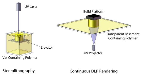
Stereolithography- and cDLP-based systems both rely on photocrosslinking for freeform fabrication. However, the methods differ as illustrated here. Stereolithography typically requires a deep vat of resin. As parts are built, they attach to an elevator which moves downward through the polymer resin as each layer is rendered at the surface by a moving laser. In contrast, cDLP systems render parts by projecting an image through a clear basement plate into a tray containing the resin, curing at the bottom surface rather than the top surface. The parts attach to a build platform which moves upward, away from the basement plate, after each layer is projected.
2.2 Liquid polymers for SLA and cDLP
Both SLA and cDLP require light polymerizable polymers. As additive manufacturing technologies, both are very different than the use of translucent molds to cure parts in a UV bath, in that the polymerization reaction must be initiated in a small, temporarily irradiated region, and by the energy emitted from the available light source. However, the photochemistry of this time- and space-delimited reaction can be similar or the same in both devices.
The UV laser in 3D Systems SLA devices generates roughly 6 orders of magnitude higher power than the lamp-based system in envisionTEC cDLP devices. SLA devices are most commonly used to render parts quickly and then post-cure them in a UV bath. On a layer to layer basis, a much longer exposure time is used in cDLP devices. Layer rendering time in our application is seconds in the former and minutes in the latter.
The production of tissue engineering scaffolds via SLA or cDLP has focused on resorbable polymers. The polymers studied to date include PPF (Dean et al. 2010) and fumaric acid monoethyl ester (FAME) end-functionalized poly(D,L-lactide) (PDLLA) oligomers and N-vinyl-2-pyrrolidone (Jansen et al. 2009). Resorption kinetics and toxicity will likely limit the list of light-polymerizable polymers that can be used for rendering tissue engineering scaffolds.
The most obvious difference between SLA and cDLP is the hardware (Figure 1). With SLA a part descends downward into the resin whereas it is pulled upward out the resin in a cDLP device. The SLA process is gentler on the forming implant than the cDLP process because, in cDLP, the part must attach much more firmly to the build platform to prevent damage when newly formed layers are peeled from the basement plate after each exposure. However SLA requires that the resin surface be uniformly flat before the exposure of each new layer, perhaps requiring the use of a “recoating” or “wiper” blade to mechanically smooth the surface. In comparison, in cDLP a new layer of resin must form underneath the scaffold on the light transmitting basement plate before the scaffold is re-positioned to render the next layer. The envisionTEC Perfactory cDLP device allows resin to spread over the basement plate passively between the rendering of each layer.
Another difference between SLA and cDLP is in the user’s ability to set the level of curing during rendering. The overall strategy with the SLA is to draw parts in relatively high molecular weight resins (i.e., high in comparison to the PPF that we use) as quickly as possible so that they can be moved to a post-curing device (e.g., a UV bath). Because we have used a dye to limit the depth of polymerization when we use the cDLP device, we have had the option of using higher levels of irradiance without losing resolution in the z direction. The use of higher levels of energy deposition may increase scaffold “green strength” (i.e., strength immediately after rendering but before post-curing). In general, increased green strength will make it easier to handle a scaffold and, more specifically, to mechanically clean unpolymerized resin from the scaffold’s internal pore space prior to post-curing (Dean et al. 2010).
2.3 System for the use of poly(propylene fumarate)
The resin that we have used for SLA or cDLP rendering of scaffolds has contained between a 1:1 and a 2:1 weight ratio of PPF to DEF and between 0.5-2.0 wt% photoinitiator. In all cases the photoinitiator used in our studies has been bis(2,4,6-trimethylbenzoyl)phenylphosphine oxide (BAPO) (Ciba Specialty Chemicals, Tarrytown, NY). Additionally, we have used a dye for cDLP rendering (see Section 2.5).
2.4 Role of solvent
There are scaffold rendering issues that SLA and cDLP share and others where they differ. Both processes are susceptible to layer set-up issues when working with a highly viscous polymer. In the SLA device, highly viscous polymer may cause mounding if a wiper blade is not used, or if that blade is unsuccessful in creating a flat resin surface of the required thickness.
In cDLP a missed layer will result if insufficient polymer recoats the basement plate or there are bubbles in that layer. We have observed that when the resin used for cDLP is too viscous, a vacuum-like seal forms between the scaffold and the basement plate. Viscous resins may require a longer pause between layers, as more time is required for the flow into void spaces left in the areas where the previous layer was cured.
Use of a solvent can alleviate these issues by reducing the resin’s viscosity. We have used the monomer precursor, diethyl fumarate (DEF), to poly(propylene fumarate) (PPF) in our work. This monomer is incorporated into the cross-linked network which forms the scaffold, but once cross-linked poses little to no toxicity risk.
2.5 Role of dye-initiator package
The relationship between depth of polymerization and exposure in SLA is determined for each resin via a calibration procedure referred to as rendering “WINDOWPANESTM” (3D Systems) (Dean et al. 2010). Once an acceptable “Z” resolution is obtained, the calibration is set for all cases. As noted in Section 2.2, the user can set the level of irradiance in cDLP. By varying irradiance versus initiator and dye concentration, one can determine curing depth. Rather than a single setting, curing depth can be experimented with until an optimal “overcure” (i.e., “stitching” between layers) is found relative to layer thickness (Figure 2). The use of dye-initiator packages has been a constant in industry (A. Siblani: Personal Experience, 14 June 2011), where toxicity issues for internal use are less prevalent. However, we expect that this topic will receive renewed interest in light of the need for biocompatible dyes and initiators for use in cDLP-based, and possibly with SLA-based, applications of additive manufacturing technologies for tissue engineering (Heller et al. 2009, Melchels et al. 2010, Seck et al. 2010).
Figure 2.

The basic steps necessary in the calibration of a cDLP system are shown here. The blue arrows indicate a logical calibration order, while the dashed arrow indicates that Steps 5 and 6 may feed back into subsequent iterations of the calibration loop.
3. Dye-Initiator Packages for Additive Manufacturing Technologies
3.1 Primary function of the dye
The primary function of the dye is to attenuate light so that as much energy as is useful can be deposited in a layer of calibrated thickness. In some cases this will be accomplished by light absorption. Thus the dye will compete with the initiator for photons. With one dye that we have studied, titanium dioxide (TiO2), light is primarily scattered rather than absorbed. The light is not only reflected directly back towards the light source, there is a possibility that there will be polymerization near the scaffold in areas which are not intentionally or directly exposed. Indeed, we have observed this, and refer to it as “lateral overcuring” (see Section 5).
We are in the process of determining how much TiO2 dye is incorporated into a scaffold and lost from the resin with each build. From our current observations it appears that it is less than 1:1 with polymer, solvent, or initiator. This was evidenced by the finding that when using a chromium azo dye (see Section 3.2), the depth of polymerization slowly decreased for a fixed exposure level each time a scaffold build process was completed, necessitating frequent recalibration. This would suggest that the dye concentration was gradually increasing as a result of unbalanced incorporation of resin components into the cured scaffolds. This phenomenon has not yet been observed for resin containing TiO2 as the dye. Since the dye is incorporated it will determine the color of the implants. A critical property of the dye is its ability to stay suspended throughout the rendering process. It may be necessary to stop the process and re-stir the resin if the dye is settling out.
3.2 Secondary Properties of a cDLP Dye
Our initial work was with a yellow azo chromium dye, which may be toxic and/or carcinogenic (Paschoal et al. 2009). As expected, it provided excellent light-blocking properties. Although we did not measure the amounts that were incorporated, we did observe that it colored the resulting scaffolds a dark orange to red color. Similarly, we did not conduct rheological studies. In our experiments we found that azo chromium dye concentrations between 1-5% were needed to reduce single PPF layer thickness to the desired value of 120 μm. This thickness would provide 70 μm of overcuring which would be useful for binding 50 μm thick layers.
Since the dye used in a dye-initiator package is likely to be incorporated into the scaffold, it may be helpful to utilize dyes that can also positively influence scaffold surface roughness, act as antibiotics, or positively affect the scaffold degradation environment (e.g., buffer the pH if it would otherwise be too acidic or basic). We have experimented with three dyes that would be both biocompatible and, we expect, would have beneficial properties during cell attachment, tissue incorporation, and/or scaffold resorption (Figure 3). Two of these dyes, doxycycline hyclate and amphotericin B, have antibiotic properties. We were unable to reach our goal of a 120 μm thick layer of PPF even when using very high concentrations of doxycycline hyclate and initiator. Amphotericin proved more effective, but the relatively high concentration needed gave us concern about the possibility of toxicity, therefore other dyes were evaluated.
Figure 3.

The relationship between cure depth (μm) and concentration (wt%) for three biocompatible dyes (amphotericin B, doxycycline hyclate, and rutile titanium dioxide). The data for an effective, but toxic, yellow azo chromium dye is also provided for comparison. Doxycycline hyclate proved ineffective for this application, while amphotericin B and titanium dioxide proved to be promising candidates for further calibration studies (see Figure 6 for a deeper investigation of titanium dioxide). The following parameters were held constant throughout these tests: BAPO concentration = 0.5 wt%; irradiance = 200mW/dm2, exposure time = 300s. Data represents mean ± standard deviation (n=3).
The third dye evaluated, titanium dioxide, is widely available in food- or pharmacologically-safe, highly pure, formulations. Small particles of TiO2 are thought to be easily metabolized. Since it is used as a food or drug coloring agent, its optical properties are well understood. It blocks light more by scattering than by absorbing photons. There are different configurations of TiO2 crystals. The rutile form with 250-305 nm sized crystals has very useful optical properties for UV attenuation.
3.3 Properties of the Initiator
We have a long experience with BAPO for UV-based photo-crosslinking of PPF for use in tissue engineering applications (Fisher et al. 2001). Most of our work using translucent molds or in stereolithography (Dean et al. 2010) has utilized 0.5-1.0% BAPO with no dye present. Upon introducing a dye we found that these levels of BAPO were too low to achieve sufficient green strength and that it was useful to increase the level to between 1.0-2.0%. As with the azo chromium and amphotericin dyes, one could determine the maximum amount of dye and initiator needed so that higher light exposures did not increase layer thickness. Being able to infuse more light allowed us to increase green strength, increasing the success rate of layer stitching and the manufacturing process in general, and potentially reducing the need for post-rendering photo-curing.
3.4 Incorporation of the Solvent (DEF)
The solvent DEF is used primarily to reduce viscosity. As with the dye, the solvent is incorporated into the resulting scaffold. Thus, without a dye present we have determined that the mechanical properties of PPF were improved by increasing the DEF concentration to a point, due to an increase in crosslinking density. However, beyond a 75:25 PPF:DEF ratio those material properties start to degrade due to the increased distance between PPF chains during the crosslinking reaction (Fisher et al. 2002). Indeed, PPF crosslinking is hindered if relative DEF solvent concentration is that high.
4. Calibration of cDLP-based Additive Manufacturing
Our goal in the calibration study was to render scaffolds with the “plate and post” geometry (Figure 4) (Anderson and Knothe Tate 2007). These cylindrical test scaffolds are 6.0 mm in diameter and 12.4 mm in length. The diameter of the large vertical channels seen in Figure 4 is 800 μm. The “plates” are 400 μm thick and 800 μm apart from each other. The “posts” running between the plates, are 600 μm in diameter.
Figure 4.

The plate-and-post test scaffold design shown from A) isometric, B) front, and C) top viewpoints. The following dimensions characterize the geometry of this design: plate thickness = 400 μm; distance between plates (or post height) = 800 μm; vertical circular pore diameter = 800 μm; post diameter = 600 μm; overall scaffold diameter = 6 mm; overall scaffold height = 12.4 mm. The height-to-diameter ratio of the scaffold approximately 2:1, which is useful for mechanical compression testing applications. The small size of the test scaffold also lends itself to small animal model testing.
4.1 Calibration of the cDLP process
Calibration of the cDLP process consists of at least six steps (Figure 2). The first step in the calibration procedure is to polymerize single layers of the cDLP resin, i.e., PPF, DEF, BAPO, and the dye (Figure 2, Step 1). There are at least three variables to study, i.e., dye concentration, initiator concentration, and irradiance duration. Other factors that could be varied would be polymer molecular weight and polydispersity as well as irradiance level (i.e., the amount and rate at which light is applied). It is not yet clear whether these variables will always interact in a linear fashion. For example, it has been reported that TiO2 can act as a catalyst (Fujishima and Honda 1972). The goal in using TiO2 is to have a layer thickness that ensures adequate overcuring between layers, yet is thin enough to allow for a desired “z” step size and the generation of accurate geometries. Resolution in x, y, and z will determine the accuracy of desired external scaffold, and internal pore, surface morphology.
The second step is to ensure that the material properties of the chosen resin configuration will provide useful scaffolds. In some cases scaffolds will be loaded with cells and/or growth factors and immediately implanted. In other cases scaffolds will be pre-cultured (e.g., in a bioreactor) prior to implantation. It may be useful to undertake mechanical tests on both bulk material samples as well as fully rendered scaffolds. It may also be useful to study the interaction between mechanical loading of the scaffold and its degradation. Finally, it may be useful to study scaffold degradation byproducts. For example, does scaffold degradation release byproducts or affect pH in a way detrimental to seeded cells, neotissue, or the host?
The third step is to study the use of the resin to form a “burn-in” patch on the build plate of the cDLP device. We have not been able to directly cure a burn-in patch on the build plate. We, therefore, begin this process by overcuring a patch of resin on the basement plate. The overcured resin patch is then transferred to the build platform and cured onto that platform using a UV bath (ProcureTM 350, 3D Systems) followed by warming with a heat gun. Heat is used to ensure that the patch center cures to the underlying build plate, as the dye content of the resin may prevent UV penetration in the patch center. Care must be taken to allow the heated layer and build plate to cool to prevent accelerated curing kinetics when the patch is reintroduced to the device. This procedure insures that scaffolds will bind to cured PPF resin directly, rather than risk that they won’t attach to the metal build plate.
The fourth step is to transfer the scaffold CAD file to the cDLP device for rendering. The CAD file will likely contain support structures spanning the space between the scaffold and the burn-in patch. The support structures must rise sufficiently above the burn-in patch to allow resin to circulate between the burn-in patch and the scaffold during rendering of the scaffold and to allow washing out of unpolymerized resin following that procedure. It is common to use pin-point supports in SLA work. We expect that, in the cDLP device, because the build plate is pulled up out of the resin, peeled off the basement plate, and subsequently pressed back down into the resin against the basement plate, there may be more force applied to the scaffold, especially to a region like a pin-point support structure, during cDLP rendering than during SLA rendering. If this susceptibility to mechanical force during scaffold rendering becomes an issue, it may be possible to counteract those forces with an increased number and density of support structures.
The fifth step is to render a multi-layer scaffold. Enough of the scaffold should be rendered to determine if a larger, more useful scaffold, can be prepared. However, it is likely that a useful test part can be rendered in 4-6 hours. This should be enough time to render a part that tests inter-layer binding and the resolution (accuracy) of scaffold geometry relative to build parameters. Inter-layer binding requires overcuring. It is useful to ensure that there is no failed lamination, or subsequent delamination. Another question to be asked is: how accurately are the varying geometries of desired features rendered, especially in directions oblique to the build plane (x and y) and inter-build plane (z) directions? Finally, one can look at how software tools, such as anti-aliasing, affect the accuracy of the shape and dimensions of designed features.
The sixth and final step is to test the scaffolds both in vitro and in vivo. As mentioned, in vitro testing could include mechanical tests, biological environments without cells or tissues, and biological environments with cells, growth factors, and/or tissues. It is possible, indeed likely, that the results of this step, as well as the fifth step, will feed back into further optimization of the first four steps.
5. Calibration Study
The PPF was synthesized and purified as per previously described methods (Kasper et al. 2009). Briefly, DEF (Acros, Pittsburgh, PA) and propylene glycol (Acros) were reacted in a 1:3 molar ratio with hydroquinone and zinc chloride as a crosslinking inhibitor and a catalyst, respectively. This reaction created the intermediate, bis(hydroxypropyl) and ethanol as a byproduct. The intermediate was then transesterified under a vacuum to produce poly(propylene fumarate) and propylene glycol as a byproduct. The PPF was then purified and gel permeation chromatography was used to calculate the number average molecular weight (Mn = 1200Da).
We used Sachtleben (White Plains, NY) R320 TiO2 which is a 320 nm crystal. Our study found that we obtained a 133 μm layer of PPF 4.8 % TiO2 (range tested: 0-4.8 %), 2% BAPO (range tested 0.5-2%), 33% DEF (range tested: 33 and 50%), and an irradiance level of 200 mW/dm2 for 300 seconds (60 s and 300 s were tested) (Figures 5 and 6). In our single layer tests we observed something we had not seen with any other dye-initiator package, a lateral spreading (i.e., in x and y) of polymerization (i.e., lateral overcuring) beyond the intended layer boundaries. This area increased most quickly at higher concentrations of TiO2, especially with increased light input at those high dye concentrations (Table 1, Figure 7). The area of lateral overcuring was not as thickly or as strongly cured as the expected area of exposure. As with overcuring in the z direction, we expected that at an appropriate setting this would not diminish the accuracy of the rendered scaffold.
Figure 5.

Depth of polymerization (μm) was characterized as a function of titanium dioxide concentration (wt%) for five different combinations of BAPO concentration (wt%) and exposure time (s). From these tests, it was determined that a 2 wt% titanium dioxide concentration with 2 wt% BAPO and a 60 s exposure time would yield an average depth of polymerization equal to 133.3 μm. These settings could therefore be used to build in 50 μm layers with 83.3 μm of overcuring. A 200 mW/dm2 irradiance was used for these tests. Data represents mean ± standard deviation (n=3).
Figure 6.

Increasing titanium dioxide concentration led to an increased amount of lateral overcuring. Testing was performed using a 200 mW/dm2 irradiance and a 300 s exposure time. Two levels of BAPO, shown above, were tested for each titanium dioxide concentration. Data shown here represents mean ± standard deviation (n=3).
Table 1.
Percent of Lateral Overcuring*
| [BAPO] = 1 wt% | [BAPO] = 2 wt% | ||||
|---|---|---|---|---|---|
|
| |||||
| [TiO2] (wt%) |
Mean % Overcure (n=3) |
Std Dev | [TiO2] (wt%) |
Mean % Overcure (n=3) |
Std Dev |
| 0 | 0 | 0 | 0 | 0 | 0 |
| 0.1 | 0 | 0 | 0.1 | 16.67 | 0 |
| 0.2 | 36.36 | 6.8E-15 | 0.2 | 26.89 | 3.28 |
| 0.3 | 42.42 | 5.25 | 0.3 | 37.88 | 2.62 |
| 0.4 | 54.55 | 0 | 0.4 | 45.46 | 0 |
| 0.8 | 63.64 | 0 | 0.8 | 54.55 | 0 |
| 1.2 | 68.18 | 7.87 | 1.2 | 60.66 | 5.25 |
| 1.6 | 74.24 | 2.62 | 1.6 | 63.64 | 0 |
| 2 | 74.24 | 2.62 | 2 | 69.70 | 5.25 |
| 2.4 | 75.76 | 5.25 | 2.4 | 69.70 | 2.62 |
| 2.8 | 72.73 | 1.4E-14 | 2.8 | 78.79 | 2.62 |
| 3.2 | 69.70 | 5.25 | 3.2 | 77.27 | 4.55 |
| 3.6 | 68.18 | 4.55 | 3.6 | 81.82 | 0 |
| 4 | 66.67 | 5.25 | 4 | 80.30 | 2.62 |
| 4.4 | 66.67 | 2.62 | 4.4 | 78.79 | 5.25 |
| 4.8 | 69.70 | 5.25 | 4.8 | 78.79 | 5.25 |
Lateral overcuring is characterized as a function of TiO2 concentration for two different BAPO levels, 1 and 2%. Three (n=3) curing tests were performed for each TiO2/BAPO combination.
Figure 7.

A curing test sample is shown. The superimposed, red, dashed line encloses the square test pattern which is projected during the test. The material outside of this boundary was not directly exposed, but rather was polymerized due the lateral overcuring caused by scattering.
In order to quantify this phenomenon, an extra step was added to the normal curing test calibration procedure. In addition to measuring cured layer thickness, i.e. the Z dimension, the XY dimensions were also measured. The curing test procedure uses a small square-shaped test pattern of UV exposure. At each TiO2 concentration increment, the length and width of the cured square-shaped thin layer were recorded. Additionally, the length and width of the total cured area, including those areas affected by lateral overcuring, were also measured. With these data, it was possible to calculate the percent overcure. The length and width, or X and Y, measurements were averaged for each part, and this process was repeated three times (n=3) for each TiO2 and BAPO concentration (Table 1).
Next we went to building 2-plate test parts like those seen in Figure 4, which are 11 plates. The 2-plate test parts also included support structures between the first plate and the burn-in patch. These test parts were successful, although we found that it was useful to decrease the thickness of the burn-in patch. We chose to do that instead of increasing the size of the supports as this reduced PPF usage.
After rendering the 2-plate scaffolds we moved on directly to the full 11-plate scaffolds. On our first experiment we found an incomplete build and a membrane of polymerized material had formed on the basement plate. This was corrected by: (1) regularly straining out polymerized resin, (2) cleaning the basement plate at set intervals, and (3) monitoring the basement plate throughout the 16 hour build cycle. We found cleaning unpolymerized polymer from both the 2- and 11-plate scaffolds from the internal pore space to be a simple procedure using an ultrasonic alcohol bath. The scaffolds rendered for this study were shown to be accurate to within 80 μm (Table 4) as measured by a micrometer. One of the resulting implants is shown in Figure 8.
Table 4.
TiO2 Dye PPF Scaffold Accuracy – 2-Plate Test Scaffold Diameter Measurements*
| Sample Number |
Plate 1 Diameter (mm) |
Plate 2 Diameter (mm) |
|---|---|---|
| 1 | 5.90 | N/A** |
| 2 | 6.02 | 5.83 |
| 3 | 5.93 | 5.92 |
| 4 | 5.97 | 5.84 |
|
| ||
| Mean | 5.92 | |
| Std Dev | 0.07 | |
Four 2-plate test scaffolds were rendered using a 150 s exposure time and a 200 mW/dm2 irradiance. The resin used for these samples contained a 2:1 PPF/DEF ratio with 2 wt% BAPO and 1 wt% TiO2. For each test scaffold, the diameter of each plate was measured using digital calipers. The expected diameter was 6.0 mm. The observed error is approximately 2 times the Perfactory device’s tolerance of 35 microns.
This plate rendered well but was damaged during post-processing.
Figure 8.

A photograph of a full plate-and-post scaffold rendered using a 1:1 PPF/DEF ratio with 1.5 wt% BAPO and 0.75 wt% TiO2. A 200 mW/dm2 irradiance and 150s exposure time were used.
As a control the same calibration study was performed using a yellow azo chromium dye, Meco Fast Yellow Y-57 (Ming Zu, Taipei, Taiwan). The plate and post diameters results of this study have been previously reported (Table 2) (Wallace et al. 2010) and we report the plate thicknesses here (Table 3). These scaffolds are depicted in Figure 9.
Table 2.
Azo-Chromium Dye PPF Scaffold Accuracy – Measurements of Plates and Posts for Single Plate Scaffolds
| Sample Number |
Plate Thickness (mm) |
Mean Post Diameter* (mm) |
|---|---|---|
| 1 | 0.45 | 0.64 |
| 2 | 0.41 | 0.66 |
| 3 | 0.42 | 0.63 |
| 4 | 0.41 | 0.62 |
| 5 | 0.41 | 0.63 |
| 6 | 0.40 | 0.61 |
| 7 | 0.43 | 0.63 |
| 8 | 0.46 | 0.63 |
| 9 | 0.41 | 0.60 |
| 10 | 0.45 | 0.64 |
|
| ||
| Mean | 0.43 | 0.63 |
| Std Dev | 0.02 | 0.01 |
For each test scaffold, four post diameter measurements were collected and averaged.
Table 3.
Azo-Chromium Dye PPF Scaffold Accuracy – Full Scaffold Diameter Measurements
| Sample Number |
Exposure Time (min) |
Mean Scaffold Diameter* (mm) |
Std Dev (mm) |
|---|---|---|---|
| 1 | 4 | 6.03 | 0.03 |
| 2 | 4 | 6.02 | 0.02 |
| 3 | 2 | 5.83 | 0.03 |
| 4 | 2 | 5.83 | 0.03 |
| 5 | 2 | 5.85 | 0.04 |
| 6 | 2 | 5.82 | 0.02 |
| 7 | 2 | 5.83 | 0.02 |
| 8 | 2 | 5.85 | 0.03 |
The diameter of each sample was measured in ten random locations (n=10) along the 12.4 mm length of the scaffold.
Figure 9.

Scaffolds rendered using an azo-chromium based dye are illustrated here in several formats. A) Scanning electron microscope (SEM) image of full scaffold (Note fish eye lens artifact); B) SEM zoomed view of Full Scaffold features. Note pixelation of surfaces (in plane); C) Top view of “plate”; D) Oblique view of scaffold features. E) Side view of scaffold features as reconstructed from μCT. E) Oblique view of the μCT data set.
6. Discussion
The creation of dye-initiator packages for cDLP rendering of tissue engineering scaffolds requires, at minimum, a dye that is biocompatible and attenuates light in the near UV (400-300 nm) and/or middle UV (300-200 nm). Since the dye is incorporated into the scaffold it may be desirable if that dye: has antibiotic properties, causes surface roughness, has a cell-signaling function, or has a chemical function (e.g., pH buffering). In choosing TiO2, we were confident in its biocompatibility and light-blocking capabilities.
We were initially concerned by what appeared to be an increased level of unintended polymerization (i.e., lateral overcuring). However, we hypothesize that polymerization is not only carried out beyond the build envelope in x and y but that it is also occurring in oblique directions in the layer of polymer that is present in the basement tray of the cDLP device. We expect that the high refractive index of TiO2 is causing light scattering. However, while this scattering is in many directions, rather than only in the “z” direction, if the amount of solid layer curing continues to occur only in the “z” direction, we see no reason to be more concerned than if one were trying to calibrate the amount of interlayer overcuring alone. There will be no interlayer overcuring in other directions as there will be no additional layers to the sides and the layers above the current location are not yet in existence.
Of greater concern was the gradual accumulation of a second membrane on the basement plate due to the lateral overcure. While we could manage this, we found that we were also straining the resin more frequently than has been our experience with an SLA device. This was a necessary step to remove cured resin floating free in the basement tray and prevent such material from interfering with proper layer curing. Unintended curing may have been enhanced because the resin chamber is not cooled, has a high degree of resin surface area exposed to warm air, and possibly there was ambient light not filtered by the device’s housing during our use of the device. Polymerization is always occurring, but given these factors and the relatively high initiator concentration, if it is possible, it might be best to have a good supply of fresh polymer during calibration procedures and to run the machine as continuously as possible at other times to reduce light and heat exposure. In addition to light blocking it may be interesting to investigate dyes that absorb light. Light absorbing dyes, initiators, or solvents might better preserve the shelf life of the resin.
Current cDLP devices can provide native accuracies of up to 13 μm in z and 42 μm in x and y, and up to 21 μm in x and y when using anti-aliasing software. Resolution has increased as newer generations of these devices have been released. This is clearly sufficient resolution to prepare patient-specific implants (Dean et al. 2003). This resolution may be sufficient to render features (e.g., surface roughness) that cells might respond to.
7. Conclusions
Our experiments with SLA rendering of PPF scaffolds did not use a dye-initiator package. In those experiments using 800 Da PPF (Dean et al. 2010), we were unable to render layers of less than 400 μm. Using 1200 Da PPF, we used a cDLP device to render layers as thin as 60 μm. The resulting highly accurate scaffolds are likely to allow improvements in the modeling, prediction, and eventual design of scaffold-specific cell attachment, proliferation, maturation, and resorption parameters.
The increase in green strength over SLA-rendered, low molecular weight, PPF scaffolds was also a significant improvement (Dean et al. 2010). We hypothesize that there are at least two reasons for the increased resolution and improved green strength over SLA-rendered scaffolds. First, the cDLP device’s software allows more user control over the build parameters and, second, we expect that the SLA controller software results in the deposition of less energy in the x, y, and z directions prior to post-curing. It is optimized to quickly draw the part to minimize build time, relying on post-curing in a UV bath to achieve complete curing and final part strength. This also reduces the use of the UV laser. Green strength is less of an issue with the relatively higher molecular weight polymers commonly used in many commercial rapid prototyping and additive manufacturing activities.
We expect that scaffold rendering resolution will continue to increase with further iterations of cDLP devices (e.g., the envisionTEC Perfactory 4). Higher resolution devices may allow the rendering of features that cells can recognize, such as pore geometries that promote tissue formation or vascular invasion or features that mimic tissue surface roughness. Part of the increase will be from refinements to cDLP technology and part of the increase may be from the use of dye-initiator packages which allow the production of highly accurate features with sufficient green strength to allow aggressive post-rendering handling, especially the removal of supports and unpolymerized resin. Finally, we expect that cDLP dye-initiator packages can be further optimized to bring about post-implantation benefits to scaffold resorption and neotissue incorporation.
Acknowledgements
This research was partially supported by the Research Foundation of the Department of Neurological Surgery, Case Western Reserve University, Cleveland, OH and by NIH grant R01-DE013740. We wish to thank Ms. Yueshuo Xu for her assistance in collecting the TiO2/BAPO dye-initiator calibration data.
Contributor Information
David Dean, Department of Neurological Surgery, Case Western Reserve University, 10900 Euclid Avenue, Cleveland, OH 44106 USA.
Jonathan Wallace, Department of Biomedical Engineering, Case Western Reserve University, 10900 Euclid Avenue, Cleveland, OH 44106 USA; Tel: (216) 844-1307; Fax: (216) 844-3336; Jonathan.Wallace@Case.Edu.
Ali Siblani, envisionTEC, Inc., 1100 Hilton Road, Ferndale, MI 48220 USA; Tel: (248) 582-0038; Fax: (248) 582-0039; asiblani@envisiontec.com.
Martha O. Wang, Fischell Dept. of Bioengineering, 3238 Jeong H. Kim Engineering Bldg (JHKEB) University of Maryland, College Park, Maryland 20742 USA; Tel: (301) 405-8782; Fax: (301) 405-0523; marthaeowang@gmail.com
Kyobum Kim, Dept. of Bioengineering, Rice University, MS 142, P.O. Box 1892, Houston, TX 77251-1892 USA; Tel: (713) 348-3009; Fax: (713) 348-4244; sallidal@gmail.com
Antonios G. Mikos, Dept. of Bioengineering, Rice University, MS 142, P.O. Box 1892, Houston, TX 77251-1892 USA; Tel: (713) 348-5355; Fax: (713) 348-4244; mikos@rice.edu
John P. Fisher, Fischell Dept. of Bioengineering, 3238 Jeong H. Kim Engineering Bldg (JHKEB) University of Maryland, College Park, Maryland 20742 USA; Tel: (301) 405-7475; Fax: (301) 405-0523; jpfisher@umd.com
References
- Alves CM, Yang Y, Marton D, Carnes DL, Ong JL, Sylvia VL, Dean DD, Reis RL, Agrawal CM. Plasma surface modification of poly(D,L-lactic acid) as a tool to enhance protein adsorption and the attachment of different cell types. J Biomed Mater Res B Appl Biomater. 2008;87(1):59–66. doi: 10.1002/jbm.b.31068. [DOI] [PubMed] [Google Scholar]
- Anderson EJ, Knothe Tate ML. Design of tissue engineering scaffolds as delivery devices for mechanical and mechanically modulated signals. Tissue Eng. 2007;13(10):2525–2538. doi: 10.1089/ten.2006.0443. [DOI] [PubMed] [Google Scholar]
- ASTM F2792–10 . Standard terminology for additive manufacturing technologies. American Society for Testing and Materials; West Conshohocken, PA: [Google Scholar]
- Cheah CM, Chua CK, Leong KF, Cheong CH, Naing MW. An Automatic Algorithm for Generating Complex Polyhedral Scaffolds for Tissue Engineering. Tissue Eng. 2004;10(3-4):595–610. doi: 10.1089/107632704323061951. [DOI] [PubMed] [Google Scholar]
- Dean D, Min K-J, Bond A. Computer aided design of large-format prefabricated cranial plates. J Craniofac Surg. 2003;14(6):819–832. doi: 10.1097/00001665-200311000-00002. [DOI] [PubMed] [Google Scholar]
- Dean D, Wallace J, Kim K, Mikos AG, Fisher JP. Stereolithographic rendering of low molecular weight polymer scaffolds for bone tissue engineering. In: da Silva Bártolo PJ, de Lemos ACS, Pereira AMH, dos Santos Mateus AJ, Mendes ALA, de Moura CSM, Capela CAB, da Silva CSG, Domingues FAC, Bártolo H.M.C.daR.T.G., Almeida H. deA., Ferreira ISC, Matias JM, Alves NMF, Rodrigues SCSF, editors. Innovative developments in design and manufacturing: advanced research in virtual and rapid prototyping. CRC Press (Taylor & Francis); Boca Raton, FL: 2010. pp. 37–43. [Google Scholar]
- Fedorovich NE, Alblas J, Hennink WE, Oner FC, Dhert WJ. Organ printing: the future of bone regeneration? Trends Biotechnol. 2011;29(12):601–606. doi: 10.1016/j.tibtech.2011.07.001. [DOI] [PubMed] [Google Scholar]
- Fielding GA, Bandyopadhyay A, Bose S. Effects of silica and zinc oxide doping on mechanical and biological properties of 3D printed tricalcium phosphate tissue engineering scaffolds. Dent Mater. 2012;28(2):113–122. doi: 10.1016/j.dental.2011.09.010. [DOI] [PMC free article] [PubMed] [Google Scholar]
- Fisher JP, Dean D, Mikos AG. Photocrosslinking characteristics and mechanical properties of diethyl fumarate/poly(propylene fumarate) biomaterials. Biomaterials. 2002;23(22):4333–4343. doi: 10.1016/s0142-9612(02)00178-3. [DOI] [PubMed] [Google Scholar]
- Fisher JP, Holland TA, Dean D, Engel PS, Mikos AG. Synthesis and properties of photocross-linked poly(propylene fumarate) scaffolds. J Biomater Sci Polym Ed. 2001;12(6):673–687. doi: 10.1163/156856201316883476. [DOI] [PubMed] [Google Scholar]
- Fujishima A, Honda K. Electrochemical photolysis of water at a semiconductor electrode. Nature. 1972;238(5358):37. doi: 10.1038/238037a0. [DOI] [PubMed] [Google Scholar]
- Heller C, Schwentenwein M, Russmueller G, Varga F, Stampfl J, Liska R. Vinyl esters: low cytotoxicity monomers for the fabrication of biocompatible 3D scaffolds by lithography based additive manufacturing. J Polym Sci A Polym Chem. 2009;47(24):6941–6954. [Google Scholar]
- Hollister SJ. Porous scaffold design for tissue engineering. Nat. Mater. 2005;4:518–524. doi: 10.1038/nmat1421. [DOI] [PubMed] [Google Scholar]
- Jansen J, Melchels FP, Grijpma DW, Feijen J. Fumaric acid monoethyl esterfunctionalized poly(D,L-lactide)/N-vinyl-2-pyrrolidone resins for the preparation of tissue engineering scaffolds by stereolithography. Biomacromolecules. 2009;10(2):214–220. doi: 10.1021/bm801001r. [DOI] [PubMed] [Google Scholar]
- Kasper FK, Tanahashi K, Fisher JP, Mikos AG. Synthesis of poly(propylene fumarate) Nat Protoc. 2009;4(4):518–525. doi: 10.1038/nprot.2009.24. [DOI] [PMC free article] [PubMed] [Google Scholar]
- Khoda AK, Ozbolat IT, Koc B. Engineered tissue scaffolds with variational porous architecture. J Biomech Eng. 2011;133(1):011001. doi: 10.1115/1.4002933. [DOI] [PubMed] [Google Scholar]
- Melchels FP, Feijen J, Grijpma DW. A review on stereolithography and its applications in biomedical engineering. Biomaterials. 2010;31(24):6121–6130. doi: 10.1016/j.biomaterials.2010.04.050. [DOI] [PubMed] [Google Scholar]
- Naing MW, Chua CK, Leong KF, Wang Y. Fabrication of Customized Scaffolds Using Computer Aided Design and Rapid Prototyping Techniques. Rapid Prototyping Journal. 2005;11(4):249–259. [Google Scholar]
- Park JS, Chu JS, Tsou AD, Diop R, Tang Z, Wang A, Li S. The effect of matrix stiffness on the differentiation of mesenchymal stem cells in response to TGF-β. Biomaterials. 2011;32(16):3921–3930. doi: 10.1016/j.biomaterials.2011.02.019. [DOI] [PMC free article] [PubMed] [Google Scholar]
- Paschoal FM, Anderson MA, Zanoni MV. Simultaneous removal of chromium and leather dye from simulated tannery effluent by photoelectrochemistry. J Hazard Mater. 2009;166(1):531–537. doi: 10.1016/j.jhazmat.2008.11.058. [DOI] [PubMed] [Google Scholar]
- Peltola SM, Melchels FP, Grijpma DW, Kellomäki M. A review of rapid prototyping techniques for tissue engineering purposes. Ann Med. 2008;40(4):268–280. doi: 10.1080/07853890701881788. [DOI] [PubMed] [Google Scholar]
- Pfister A, Landers D, Laib A, Hubner U, Schmelzeisen R, Muhaupt R. Biofunctional rapid prototyping for tissue-engineering applications: 3D bioplotting versus 3D printing. J Polym Sci A Polym Chem. 2004;42(3):624–638. [Google Scholar]
- Schek RM, Wilke EN, Hollister SJ, Krebsbach PH. Combined use of designed scaffolds and adenoviral gene therapy for skeletal tissue engineering. Biomaterials. 2006;27(7):1160–1166. doi: 10.1016/j.biomaterials.2005.07.029. [DOI] [PubMed] [Google Scholar]
- Seck T, Melchels F, Feijen J, Grijpma D. Designed biodegradable hydrogel structures prepared by stereolithography using poly(ethylene glycol)/poly(d,l-lactide)-based resins. J Control Release. 2010;148(1):34–41. doi: 10.1016/j.jconrel.2010.07.111. [DOI] [PubMed] [Google Scholar]
- Song MJ, Dean D, Knothe Tate ML. In situ spatiotemporal mapping of flow fields around seeded stem cells at the subcellular length scale. PLoS One. 2010;5(9):e12796. doi: 10.1371/journal.pone.0012796. [DOI] [PMC free article] [PubMed] [Google Scholar]
- Sun M, Lv D, Zhang C, Zhu L. Culturing functional cartilage tissue under a novel bionic mechanical condition. Med Hypotheses. 2010;75(6):657–659. doi: 10.1016/j.mehy.2010.08.011. [DOI] [PubMed] [Google Scholar]
- Vehof JW, Fisher JP, Dean D, van der Waerden JP, Spauwen PH, Mikos AG, Jansen JA. Bone formation in transforming growth factor beta-1-coated porous poly(propylene fumarate) scaffolds. J Biomed Mater Res. 2002;60(2):241–251. doi: 10.1002/jbm.10073. [DOI] [PubMed] [Google Scholar]
- Wallace JE, Siblani A, Wang M, Kim K, Fisher JP, Mikos AG, Dean D. Highly accurate rendering of tissue engineered scaffolds via continuous DLP polymerization. Abstract. Presented October 5, 2010 at the 2010 International Conference on Biofabrication; Philadelphia, PA. 2010. [Google Scholar]
- Yoo DJ. Porous scaffold design using the distance field and triply periodic minimal surface models. Biomaterials. 2011;32(31):7741–7754. doi: 10.1016/j.biomaterials.2011.07.019. [DOI] [PubMed] [Google Scholar]