

Abstract.
Intervertebral cages in the lumbar spine have been an advancement in spinal fusion to relieve low back pain. Even though initial stability is accepted as a requirement for fusion, there are other factors. The load transfer and its effect on the tissues adjacent to the cage may also play an essential role, which is not easily detectable with experimental tests. In this study the effects of an intervertebral cage insertion on a lumbar functional spinal unit were investigated using finite element analyses. The influences of cage material, cancellous bone density and spinal loading for the stresses in a functional spinal unit were evaluated. Three-dimensional (3D) finite element models of L2-L3 were developed for this purpose. An anterior approach for a monobloc, box-shaped cage was modelled. Models with cage were compared to the corresponding intact ones. The results showed that inserting a cage increased the maximum von Mises stress and changed the load transfer in the adjacent structures. Varying the cage material or the loading conditions had a much smaller influence than varying the cancellous bone density. The denser the cancellous bone, the more the stress was concentrated underneath the cage, while the remaining regions were unloaded. This study showed that the density of the underlying cancellous bone is a more important factor for the biomechanical behaviour of a motion segment stabilized with a cage, and its eventual clinical success, than the cage material or the applied load. Inserting an intervertebral cage markedly changed the load transfer. The altered stress distribution may trigger bone remodelling and explain damage of the underlying vertebrae.
Keywords. Finite element analysis, Lumbar spine, Intervertebral cage, Stress distribution
Introduction
Intervertebral cages in the lumbar spine have been a promising advancement in spinal fusion. The final goal of the procedure is to relieve low back pain, one of today's major and most expensive health care problems. A large number of cages exist, which are different in design, material and surgical implanting approach. Several clinical follow-up studies have been published, mostly reporting high fusion rates, even though the criteria for success are inconsistent [1, 5, 17, 18, 23, 25, 30, 31]. Additionally, there have been reports of mechanical failure, subsidence and migration [23, 39, 42]. The success of a cage insertion, which is regarded as fusion, and thereby stabilisation, of the spine, in addition to the biological factors, may be dependent on other parameters, including material properties of the vertebrae or the cage, geometry of the implant, and the interface between the bone and the cage [23, 25, 39, 43].
Hence, experimental and finite element studies have been carried out to investigate the influence of these factors on biomechanical behaviour, especially on initial stability. Grosland et al. [13] presented a comparative finite element investigation of multiple interbody fusion cages. The implantation of five different cage designs in a functional spinal unit was modelled, and these models were subjected to compression, flexion and extension. The results showed that various cage designs led to little variation in the resulting stiffness. Experimental studies have been done using animal and human cadaver models. The influence of implant design, additional posterior instrumentation, surgical approach and bone mineral density on stiffness, compressive strength and three-dimensional flexibility under static, quasi-static and cyclic loading have been investigated [11, 14, 15, 20, 27, 28, 29, 38, 40, 43]. Summarising their review of biomechanical cage studies on human specimens, Oxland and Lund stated that the anterior approach produced better initial stability than the posterior one, that adding a posterior fixation creates the most stable construct, and that vertebral bone density played a very important role for the compressive strength of the interface between cage and vertebra [27]. The conclusions of all these studies have shown that the density of the adjacent vertebrae was a more important factor for the stabilisation of the spine – for its compressive strength, flexibility and stiffness – than the cage design.
Several questions still remain unanswered, however, and it is not clear which mechanical and biological conditions are necessary to achieve fusion and long-term clinical success. Initial stability is regarded as one pre-requisite for fusion, and is influenced by various parameters. Examining the consequences of parameter variations on the same specimen provides better insight into the amount to which certain factors may influence the clinical outcome. This cannot be achieved in experimental studies due to the variability of cadaver specimens. In contrast, analytical approaches are able to evaluate the influence of certain parameters on one specimen. The objectives of this study were therefore to evaluate the importance of cage material, cancellous bone density and spinal loading for the distribution and magnitude of stresses in the vertebrae by means of a physiological finite element model.
Materials and methods
Three-dimensional finite element models of a functional spinal unit with a cage and without were generated (Fig. 1). To create these models, computed tomography (CT) scans of an L2-L3 motion segment of a healthy young male were obtained. The sections were automatically reconstructed to 1-mm-thick slices with a 1-mm interval by the scanner. With custom-made software the CT data were translated and the bony parts segmented. The resulting keypoints were transferred into commercial CAD-FEM software (I–DEAS, EDS, Maryland Heights, Mo., USA), and a solid model of the two vertebral bodies and the posterior elements was built.
Fig. 1.
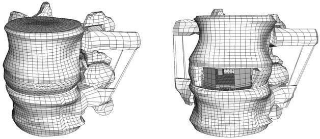
The intact finite element model (left) and the model with cage (right)
Details that were not clearly visible on the CT scans were modelled according to additional information. The shape of the inferior endplate of L2 and the superior endplate of L3 were detailed as described by Roberts et al. [32]. The initial radial bulge of the wedge-shaped intervertebral disc was modelled similar to the shape described by Brinckmann et al. [6]. The ratio between the surface areas of the nucleus pulposus and the annulus ground-substance was defined such that the area of the nucleus occupied on average 43% of the total disc area [37]. The position of the nucleus was chosen according to measurements on human specimens.
The assigned material properties were adapted from previous finite element studies and were assumed to be linear, homogeneous and isotropic. Their values and the chosen element specifications are presented in Table 1 and Table 2 . The posterior elements were modelled with material properties intermediate to those of cortical and cancellous bone as per Shirazi-Adl et al. [34]. Consistent with the published relationship between bone mineral density and elastic modulus [2, 7], the elastic modulus of cancellous bone was varied, encompassing those values of bone mineral density measured in previous studies [2, 7, 20]. The influence of others factors such as trabecular structure was, however, not considered. Cartilage layers were built on top of the bony facet joints. No cartilaginous endplates were defined on the bony ones, as their effect on load transfer was assumed to be negligible; furthermore, the cartilaginous endplate is usually removed prior to cage insertion.
Table 1.
Material properties and element specifications for the bony parts and the cartilage of the model (C3D indicates the elements are continuum three-dimensional elements; the number that follows indicates the number of nodes)
| Material | Element type | Elastic modulus (MPa) | Poisson ratio | No. of elements | References | |
|---|---|---|---|---|---|---|
| Total | L2/L3 | |||||
| Cancellous | 8-node brick C3D8 | Varied: 30, 50, 100a, 200, 500, 1000 | 0.2 | 20160 | 10,368/9792 | [2, 7, 20, 31, 34] |
| Corticalis | C3D8 | 12,000 | 0.3 | 1680 | 864/816 | [34] |
| Endplate | C3D8 | 1000 | 0.4 | 1872 | 624 each | [36] |
| Posterior elements | 6-node wedge C3D6 | 3500 | 0.25 | 4 | 1069/700 | [35] |
| 4-node tetrahedral C3D4 | 5 | |||||
| C3D8 | 1760 | |||||
| Cartilage | C3D8 | 10 | 0.4 | 96 | 2*24 each | [10, 16] |
a The 100 MPa modulus comes from Shirazi-Adl et al. [34]
Table 2.
Material properties and element specifications for the annular fibres and the ligaments (T3D2 three-dimensional two-node truss elements)
| Material | Element type | No. of elements (in cage model) | Elastic modulus (MPa) | Poisson ratio | Referencea, cross sectional area (mm2) |
|---|---|---|---|---|---|
| Annulus fibre layers | T3D2 | ||||
| Outermost | 480 (339) | 550 | 0.3 | 0.7 | |
| Second | 480 (340) | 495 | 0.3 | 0.63 | |
| Third | 480 (338) | 440 | 0.3 | 0.55 | |
| Fourth | 480 (335) | 420 | 0.3 | 0.49 | |
| Fifth | 480 (317) | 385 | 0.3 | 0.41 | |
| Innermost | 480 (0) | 360 | 0.3 | 0.30 | |
| Ligaments | T3D2 | ||||
| Lig. long. anterius | 45 (0) | 20 | 0.3 | 38 | |
| Lig. long. posterius | 35 | 70 | 0.3 | 20 | |
| Lig. flava | 13 | 50 | 0.3 | 60 | |
| Lig. intertransversia | 12 | 50 | 0.3 | 10 | |
| Lig. interspinalia | 6 | 28 | 0.3 | 35.5 | |
| Lig. supraspinalia | 6 | 28 | 0.3 | 35.5 | |
| Lig. capsulae | 20 | 20 | 0.3 | 40 |
The annulus fibrosus was modelled as a composite material comprising a series of 12 fibre bands embedded between ground-substance layers [35]. For the fibres, "tension only" three-dimensional truss elements were used and arranged in space at an average of 123.5° to each other in the outermost and 85.4° in the innermost layers in a criss-cross pattern. Those values are in agreement with the observed variety in fibre angles [22, 41]. The fibre cross-sectional areas varied along the radial direction of the annulus to reflect the unequal distribution and properties of this structure. Their material properties were adapted based on the work of Shirazi-Adl et al. [34] and Smit et al. [37] (Table 2 ). The ground-substance was constructed with 1440 three-dimensional eight-node brick elements (elastic modulus 4.2 MPa, Poisson ratio 0.45 [34]). The nucleus pulposus was built using 1680 three-dimensional eight-node hybrid elements, which are intended for use with almost incompressible material behaviour (elastic modulus 0.2 MPa, Poisson ratio 0.4999 [33]).
Seven different ligaments being active in tension only were also modelled with truss elements (Table 2 ). These elements were orientated along the respective ligament directions obtained from anatomical textbooks. The intact, ligamentous model of the functional spinal unit consisted of 31,714 elements.
Model of the intervertebral cage
Intervertebral cages inserted from anterior provide better initial stability, and a wider cage with an open frame design appears to have biological advantages [27, 39, 40]. A wide, open monobloc cage can provide more space for graft material and thereby a larger possible interface between graft material and host bone, which is thought to promote fusion [4]. Therefore, the design of our cage model was based on the Syncage (Mathys Medical Ltd., Bettlach, Switzerland), a so-called monobloc, box-shaped cage for anterior or antero-lateral insertion (Fig. 2).
Fig. 2.
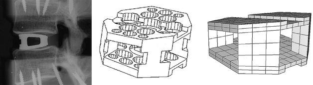
Lateral radiograph of the original cage (left), in-house computer-assisted design drawing of the cage (middle), basis for the finite element model (right)
Titanium and carbon fibre material properties were assigned to the cage model, representing the two basic material types used for interbody implants. As the focus in this part of our study was on the initial, postoperative situation, bone ingrowth was not modelled. Therefore, design details such as holes or grooves were not included. Consequently, the elastic modulus of the cage materials was reduced according to the calculated ratios between the secondary moments of area between the original cage and a corresponding solid model, to take into account the more rigid, solid faces of the model. Accordingly, a modulus of 77 GPa was defined for titanium and of 38.5 GPa for carbon fibre, both had a Poisson ratio of 0.3. Each finite element cage model consisted of 312 eight-node brick and 52 six-node wedge elements. The appropriate cage size was chosen according to the space between the vertebrae, as proposed by the manufacturer to restore lordosis and disc height.
The original implant is convex to mimic the concave contours of the endplates. This convex shape was not included in the model, as the fit between the curved endplates and a flat implant would represent a worst-case scenario, and is realistic for quite a number of existing cages. For the insertion of the cage, an anterior approach was modelled (Fig. 1) and the anterior longitudinal ligament, the nucleus pulposus and the necessary amount of fibre (Table 2 ) and annular elements were removed to fit the cage.
Contact definition
The facet joints were treated as a nonlinear three-dimensional contact problem, including friction. Finite-sliding interaction was defined, allowing any arbitrary motion of the surfaces, i.e. separation, sliding and rotation. A classical isotropic Coulomb friction model was chosen, but to the authors' knowledge no data are available regarding the value of the friction coefficient in this joint. According to the data of McCutchen [24], a relatively high friction coefficient of 0.1 was assigned as a worst-case scenario.
Because of the strong incongruency between the surfaces of the cage and the anatomically curved endplates, a surface-based contact definition was not applicable for this interface. Therefore, gap elements were introduced. The contact direction was chosen to be perpendicular to the cage surfaces. For the definition of the interaction between implant and bone, a literature search yielded few data concerning the friction coefficient [8, 21]. The reported values were related to friction between hip implants and the surrounding femur. As most intervertebral implants have small teeth or serrations on the contact surfaces that are supposed to prevent motion of the implant, a higher friction coefficient of 0.8 was defined between the cage and the adjacent endplates.
Load, boundary conditions
To homogenise the load influence, the forces were distributed to the nodes on the superior surface of the motion segment, a flat endplate on top of L2 (thickness 0.6 mm) and the uppermost nodes of the corresponding posterior elements. The following loading conditions were modelled with a resultant vertical force of 1000 N: pure compression, flexion, extension and lateral bending. To produce the latter load cases, the magnitudes of the vertical forces were varied in a ramp profile across the endplate and the posterior elements, producing a compression load superimposed with the desired moments. Depending on the varying positions of the helical axis of motion for flexion, extension and lateral bending, the loads amounted to a maximum net moment of approximately 12 Nm on the functional spinal unit.
To obtain convergence, a series of load steps was applied [26]. The inferior surface of L3 was constrained. All models with cages were compared to the corresponding intact ones. The commercially available software ABAQUS version 5.8 (HKS, Pawtucket, R.I., USA) was used as a solver for these nonlinear analyses.
Results
Inserting an intervertebral cage altered the stress distribution in the functional spinal unit. Varying the cancellous bone properties led to more pronounced changes of the load transfer than changing the cage material properties, but to smaller alterations than the implantation itself. Typical examples for the von Mises stress distribution in the cancellous bone of L3 resulting from compression load and different bone densities are presented in Fig. 3. It is clearly visible that the magnitude of the von Mises stress following cage insertion exceeds the stress in the intact case. Additionally, a distinct difference in the stress distribution and the corresponding load transfer through the cancellous bone can be seen between the two cases. A similar distribution was seen for all different densities considered, as is evident from the examples shown in Fig. 3.
Fig. 3.
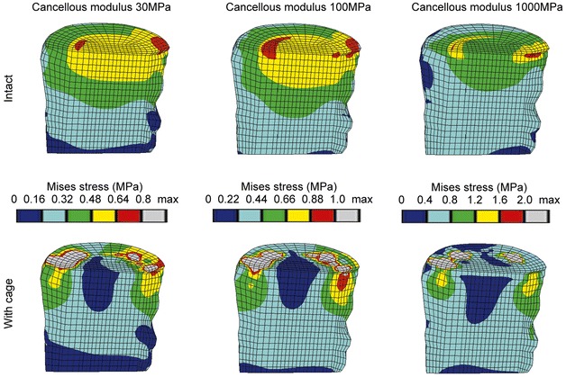
Von Mises stress distributions for intact cases (top row) and models with a titanium cage (bottom row) under uniform compression of 1000 N. A sagittal cut through the cancellous core of L3 is shown, anterior is to the left. The displayed limits for the colour bands are based on the intact case, please note that they are not identical
The denser the cancellous bone, the more the stress was concentrated in the contact areas between cage and bone, while the remaining regions were unloaded. This finding was confirmed when the magnitudes of the stresses were considered. Examples for the percentile differences of the maximum von Mises stress in the L3 vertebral body between an intact and a cage model due to varied material properties are depicted in Table 3 . Results from discrete element subsets lying in the sagittal plane at an anterior, middle and posterior position (Fig. 4) are presented. The locations below the central slot of the modelled implant were chosen to minimize possible artefacts resulting from contact force peaks. Between the intact models with different cancellous elastic moduli, the biggest difference in the maximum von Mises stress was found in the middle subset, and amounted to 99% when the modulus was increased from 30 MPa to 1000 MPa. Conversely, changing the cage material had a negligible influence on the resulting stresses. Using a carbon fibre cage instead of a titanium one altered the stress in both vertebrae by less than 2%. The insertion of a cage itself, in contrast, increased the stress in the L3 body by +217% maximum compared to the intact model, for a cancellous elastic modulus of 1000 MPa.
Table 3.
Percentages of the maximum von Mises stress in the subsets A, B, C of the lower vertebra (Fig. 4) due to varied material properties. The corresponding intact models were set to 100%. All cages were titanium, except for one carbon fibre cage
| Model with: | A | B | C |
|---|---|---|---|
| Cancellous elastic modulus 30 MPa | 187 | 33 | 107 |
| Cancellous elastic modulus 50 MPa | 192 | 29 | 117 |
| Cancellous elastic modulus 100 MPa | 207 | 32 | 134 |
| Carbon fibre cage, cancellous elastic modulus 100 MPa | 206 | 32 | 133 |
| Cancellous elastic modulus 200 MPa | 223 | 34 | 150 |
| Cancellous elastic modulus 500 MPa | 275 | 34 | 170 |
| Cancellous elastic modulus 1000 MPa | 317 | 32 | 172 |
Fig. 4.
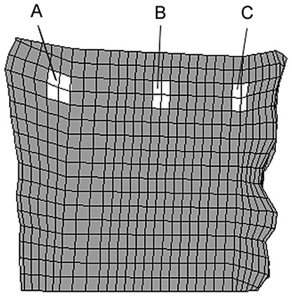
Location of the element subsets A (anterior), B (middle), C (posterior) in the vertebral body of L3. The locations below the central slot of the modelled implant were chosen to minimize possible artefacts resulting from contact force peaks
The von Mises stress distributions resulting from various loading conditions are pictured in Fig. 3 and Fig. 5. Following cage insertion, the stresses exceeded the levels of the corresponding intact models for all load cases applied. Among compression, flexion and lateral bending, the stress distribution remained relatively consistent. The biggest alterations occurred in extension. These changes indicate that varying the loading conditions altered the stress distribution to a much smaller extent than did the insertion of a cage.
Fig. 5.
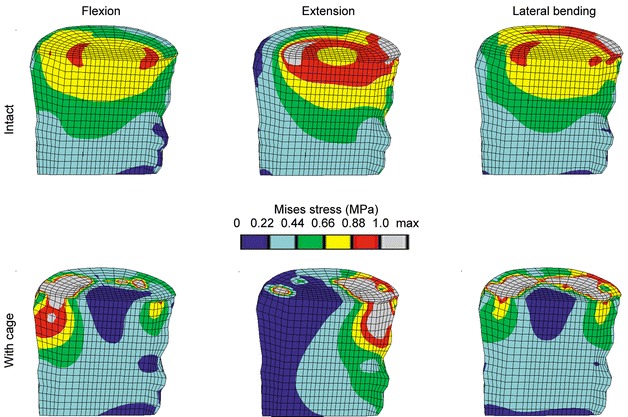
Von Mises stress distribution due to different loading conditions for the intact case (top row) and the models with cage (bottom row). The lateral bending occurs to the side shown. A sagittal cut through the cancellous bone of L3 is shown, anterior is to the left. The limits for the colour bands are based on the intact case. All models had an elastic modulus for cancellous bone of 100 MPa, and a titanium cage was used
The percentile differences of the maximum von Mises stress between an intact model and a model with cage in the element subsets of the cancellous bone of L3 for different load cases are provided in Table 4 . For flexion, the insertion of a cage had the biggest influence on the maximum stress, amounting to –80% (for the middle subset B) and +207% (for the anteriorly lying subset A) (Fig. 4), compared to the corresponding intact case. The biggest difference in the maximum stresses between the load cases was an increase of +85% at the middle position if extension was compared to compression for a model with cage.
Table 4.
Percentages of the maximum von Mises stress in the subsets A, B, C of the lower vertebra (Fig. 4) due to different load cases (values for both sides of lateral bending – denoted as 1 and 2 – are given). The corresponding intact models were set to 100%. All cages were titanium and the cancellous bone had the same elastic modulus of 100 MPa
| Loading | A | B | C |
|---|---|---|---|
| Compression | 207 | 32 | 134 |
| Flexion | 307 | 20 | 100 |
| Extension | 38 | 51 | 165 |
| Lateral bending 1 | 144 | 38 | 154 |
| Lateral bending 2 | 218 | 30 | 97 |
Discussion
Intervertebral cages have been a promising advancement in spinal fusion [1, 5, 17, 18, 30, 31]; nevertheless, the biological and mechanical requirements as well as the criteria for successful fusion are still under discussion [23, 25, 39]. This study evaluated the influence of cage insertion, cage material, cancellous bone density and spinal loading on the stress distribution in a functional spinal unit. Inserting a cage increased the stress and markedly altered the overall load transfer under all circumstances investigated. The results revealed that the density of the bone is a more important factor for the biomechanical behaviour of a cage than the cage material or the spinal loading, extending findings from experimental studies [14, 27, 28].
Although the presented finite element models were based on physiological material properties and spinal geometry, including ligaments, there were some limitations. The linear, isotropic material properties were a simplification of the real situation and non-linear definitions will be used in future studies, especially for the soft tissue. Another limitation was that for each material, the properties were homogeneous. A more physiological material distribution may have produced different stress distributions, but may also introduce numerical uncertainties. Clinically, intervertebral cages are not inserted in young healthy spines. However, in most of the experimental studies investigating the biomechanical behaviour of cages, normal functional spinal units have been used.
If intervertebral cages are implanted according to the manufacturers' instructions, the disc space is distracted, leading to tension in the annular fibres. It is believed that the contracting fibres produce compression between the cage and the vertebrae, maintaining the cage in place. Surgeons refer to this as the "distraction-compression principle" [3]. This mechanism was not modelled here, which might be considered as a limitation, but due to the viscoelastic nature of the fibres, it is unclear how long this effect would last [15].
For the investigated implant shape, contact between the cage and the endplates was concentrated at the periphery of the cage. In vivo, similar stress concentrations may overload the bone and increase the risk of subsidence. However, peripheral endplate contact was tested by Steffen et al. [38], and shown to provide similar mechanical support to that of an implant with full support. Minimizing the contact between cage and endplate provides an increased graft-host bone contact area, which enhances fusion, but may endanger the mechanical stability. The distinction between failure and success is influenced by parameters such as the size of the contact area and the endplate properties. In this study, the distribution of material properties over the endplate was considered to be homogeneous, which is not the case in reality [12]. An evaluation of the effect of endplate properties and their distribution on the initial situation of the cage-vertebrae construct is presently in process.
This study clearly showed that the insertion of a cage changes the load transfer through a functional spinal unit. The stresses were concentrated close to the contact zone and the remaining regions were unloaded. The altered stress distribution in the bony components adjacent to the inserted cage is likely to trigger biological events, leading to bone remodelling and resorption under the cage. In general this remodelling capacity is considered as a positive effect, enabling the adaptation of the bony structures to the altered loading. Nevertheless, especially if bone turnover cycles are perturbed, the bone adaptation might not be possible and these structural changes may then lead to damage of the underlying bone and subsequent subsidence of the cage.
Even though it is generally accepted that initial stability is a requirement for fusion, it has not been established how much residual segmental mobility or micromotion at the interface between implant or bone graft and host bone can be tolerated. Further studies are planned to look at the motion of the cage, with more combined loading cases and cyclic loading. In addition, material properties will be modified to represent different stages of fusion and bone ingrowth into the cage to determine how load transfer may be influenced over time. This is especially important as the long-term success of intervertebral fusion remains a matter of discussion [23, 39].
Using physiological finite element models of a functional spinal unit enabled the evaluation of cage material, cancellous bone density and spinal loading for the stresses in the vertebrae. By calculating the stress distribution for the entire motion segment, it was demonstrated how much the overall stresses are affected by various parameters, especially by bone density. These changes cannot be accessed with experimental methods except at discrete locations [9]. In addition, the variability resulting from different cadaver specimens used in experimental studies was removed. The alteration of the load transfer is likely to cause structural changes in the adjacent bone. These changes may offer an explanation for the damage occurring to the underlying bone, as well as for the subsequent subsidence of the cage.
Acknowledgements.
The authors thank Dr. Qingmao Hu for assistance with the segmentation of the CT slices.
References
- 1.Agazzi S, Reverdin A, May D (1999) Posterior lumbar interbody fusion with cages: an independent review of 71 cases. J Neurosurg 91:186–192 [DOI] [PubMed]
- 2.Augat P, Link T, Lang TF, et al (1998) Anisotropy of the elastic modulus of trabecular bone specimens from different anatomical locations. Med Eng Phys 20:124–131 [DOI] [PubMed]
- 3.Bagby G (1988) Arthrodesis by the distraction-compression method using a stainless steel implant. Orthopedics 11:931–934 [DOI] [PubMed]
- 4.Boden S, Sumner D (1995) Biologic factors affecting spinal fusion and bone regeneration. Spine [Suppl] 20:102-112 [PubMed]
- 5.Brantigan J, Steffee A, Lewis M, Quinn L, Persenaire J (2000). Lumbar interbody fusion using the Brantigan I/F cage for posterior lumbar interbody fusion and the variable pedicle screw placement system. Spine 25:1437–1446 [DOI] [PubMed]
- 6.Brinckmann P, Frobin W, Hierholzer E, Horst M (1983) Deformation of the vertebral end-plate under axial loading of the spine. Spine 8:851–856 [DOI] [PubMed]
- 7.Carter DR, Hayes WC (1976) Bone compressive strength: the influence of density and strain rate. Science 194:1174–1176 [DOI] [PubMed]
- 8.Dammak M, Shirazi-Adl A, Zukor D (1997) Analysis of cementless implants using interface nonlinear friction – experimental and finite element studies. J Biomech 30:121–129 [DOI] [PubMed]
- 9.Frei HP, Oxland TR, Rathonyi GC, Nolte LP (2001) The effect of nucleotomy on lumbar spine mechanics in compression and shear loading. Spine 26:2080–2089 [DOI] [PubMed]
- 10.Goel VK, Kong W, Han JS, Weinstein JN, Gilbertson LG (1993) A combined finite element and optimization investigation of lumbar spine mechanics with and without muscles. Spine 18:1531–1541 [PubMed]
- 11.Goh J, Wong H-K, Thambay A, Yu C-S (2000) Influence of PLIF cage size on lumbar spine stability. Spine 25:35–40 [DOI] [PubMed]
- 12.Grant J, Oxland T, Dvorak M (2001) Mapping the structural properties of the lumbosacral vertebral endplates. Spine 26:889–896 [DOI] [PubMed]
- 13.Grosland N, Goel V, Grobler L (1999) Comparative biomechanical investigation of multiple interbody fusion cages: a finite element analysis. Proceedings of the 45th Annual Meeting of the Orthopaedic Research Society, Anaheim
- 14.Jost B, Cripton P, Lund T, et al (1998) Compressive strength of interbody cages in the lumbar spine: the effect of cage shape, posterior instrumentation and bone density. Eur Spine J 7:132–141 [DOI] [PMC free article] [PubMed]
- 15.Kettler A, Wilke H-J, Dietl R, Krammer M, Lumenta C, Claes L (2000) Stabilizing effect of posterior lumbar interbody fusion cages before and after cyclic loading. J Neurosurg 92:87–92 [DOI] [PubMed]
- 16.Kumaresan S, Yoganandan N, Pintar FA (1998) Finite element modeling approaches of human cervical spine facet joint capsule. J Biomech 31:371–376 [DOI] [PubMed]
- 17.Kuslich S, Ulstrom C, Griffith S, Ahern J, Dowdle J (1998) The Bagby and Kuslich method of lumbar interbody fusion: history, techniques, and 2-year follow-up results of a United States prospective, multicenter trial. Spine 23:1267–1279 [DOI] [PubMed]
- 18.Kuslich S, Danielson G, Dowdle J, et al (2000) Four-year follow-up results of lumbar spine arthrodesis using the Bagby and Kuslich lumbar fusion cage. Spine 25:2656–2662 [DOI] [PubMed]
- 19.Lu M, Hutton WC (1996) Do bending, twisting, and diurnal fluid changes in the disc affect the propensity to prolapse? A viscoelastic finite element model. Spine 21:2570–2579 [DOI] [PubMed]
- 20.Lund T, Oxland T, Jost B, et al (1998) Interbody cage stabilisation in the lumbar spine. J Bone Joint Surg Br 80:351–359 [DOI] [PubMed]
- 21.Mann K, Bartel D, Wright T, Burstein A (1995) Coulomb frictional interfaces in modeling cemented total hip replacements: a more realistic model. J Biomech 28:1067–1078 [DOI] [PubMed]
- 22.Marchand F, Ahmed A (1990) Investigation of the laminate structure of lumbar disc anulus fibrosus. Spine 15:402–410 [DOI] [PubMed]
- 23.McAfee P (1999) Interbody fusion cages in reconstructive operations on the spine. Current concepts review. J Bone Joint Surg Am 81:859–880 [DOI] [PubMed]
- 24.McCutchen C (1962) The frictional properties of animal joints. Wear 5:1–17
- 25.Mulholland R (2000) Cages: outcome and complications. Eur Spine J 9:110-113 [DOI] [PMC free article] [PubMed]
- 26.Otto J, Callaghan J, Brown T (2001) Methods to achieve a numerically stable finite element model of a multi-contact interface rotating platform total knee. Proceedings of the 47th Annual Meeting of the Orthopaedic Research Society, San Francisco
- 27.Oxland TR, Lund T (2000) Biomechanics of stand-alone cages and cages in combination with posterior fixation: a literature review. Eur Spine J 9 [Suppl 1]:95–101 [DOI] [PMC free article] [PubMed]
- 28.Oxland T, Lund T, Jost B, et al (1996) The relative importance of vertebral bone density and disc degeneration in spinal flexibility and interbody implant performance. Spine 21:2558–2569 [DOI] [PubMed]
- 29.Oxland T, Hoffer Z, Nydegger T, Rathonyi G, Nolte L-P (2000) A comparative biomechanical investigation of anterior lumbar interbody cages: central and bilateral approaches. J Bone Joint Surg Am 82:383–393 [PubMed]
- 30.Pavlov P, Spruit M, Havinfa M, Anderson P, van Limbeek J, Jacobs W (2000) Anterior lumbar interbody fusion with threaded fusion cages and autologous bone grafts. Eur Spine J 9:224–229 [DOI] [PMC free article] [PubMed]
- 31.Ray C (1997) Threaded titanium cages for lumbar interbody fusions. Spine 22:667–680 [DOI] [PubMed]
- 32.Roberts S, McCall I, Menage J, Haddaway M, Eisenstein S (1997) Does the thickness of the vertebral subchondral bone reflect the composition of the intervertebral disc? Eur Spine J 6:385–389 [DOI] [PMC free article] [PubMed]
- 33.Sharma M, Langrana NA, Rodriguez J (1995) Role of ligaments and facets in lumbar spinal stability. Spine 20:887–900 [DOI] [PubMed]
- 34.Shirazi-Adl SA, Shrivastava SC, Ahmed AM (1984) Stress analysis of the lumbar disc-body unit in compression. A three-dimensional nonlinear finite element study. Spine 9:120–134 [DOI] [PubMed]
- 35.Shirazi-Adl A, Ahmed AM, Shrivastava SC (1986) Mechanical response of a lumbar motion segment in axial torque alone and combined with compression. Spine 11:914–927 [DOI] [PubMed]
- 36.Silva MJ, Keaveny TM, Hayes WC (1997) Load sharing between the shell and centrum in the lumbar vertebral body. Spine 22:140–150 [DOI] [PubMed]
- 37.Smit T, Odgaard A, Schneider E (1997) Structure and function of vertebral trabecular bone. Spine 22:2823–2833 [DOI] [PubMed]
- 38.Steffen T, Tsantrizos A, Aebi M (2000) Effect of implant design and endplate preparation on the compressive strength of interbody fusion constructs. Spine 25:1077–1084 [DOI] [PubMed]
- 39.Steffen T, Tsantrizos A, Fruth I, Aebi M (2000) Cages: designs and concepts. Eur Spine J 9 [Suppl 1]:89–94 [DOI] [PMC free article] [PubMed]
- 40.Tsantrizos A, Andreou A, Aebi M, Steffen T (2000) Biomechanical stability of five stand-alone anterior lumbar interbody fusion constructs. Eur Spine J 9:14–22 [DOI] [PMC free article] [PubMed]
- 41.Tsuji H, Hirano N, Ohshima H, Ishihara H, Terahata N, Motoe T (1993) Structural variation of the anterior and posterior anulus fibrosus in the development of human lumbar intervertebral disc. Spine 18:204–210 [PubMed]
- 42.Tullberg T (1998) Failure of a carbon fiber implant: a case report. Spine 23:1804–1806 [DOI] [PubMed]
- 43.Weiner K, Fraser R (1998) Spine update: lumbar interbody cages. Spine 23:634–640 [DOI] [PubMed]