Abstract
Intervertebral cages in the lumbar spine represent an advancement in spinal fusion to relieve low back pain. Different implant designs require different endplate preparations, but the question of to what extent preservation of the bony endplate might be necessary remains unanswered. In this study the effects of endplate properties and their distribution on stresses in a lumbar functional spinal unit were investigated using finite-element analyses. Three-dimensional finite-element models of L2-L3 with and without a cage were used. An anterior approach for a monobloc, box-shaped cage was modelled. The results showed that inserting a cage increased the maximum von Mises stress and changed the load distribution in the adjacent structures. A harder endplate led to increased concentration of the stress peaks and high stresses were propagated further into the vertebral body, into areas that would usually not experience such stresses. This may cause structural changes and provide an explanation for the damage occurring to the underlying bone, as well as for the subsequent subsidence of the cage. Stress distributions were similar for the two endplate preparation techniques of complete endplate preservation and partial endplate removal from the centre. It can be concluded that cages should be designed such that they rely on the strong peripheral part of the endplate for support and offer a large volume for the graft. Furthermore, the adjacent vertebrae should be assessed to ensure that they show sufficient density in the peripheral regions to tolerate the altered load transfer following cage insertion until an adequate adaptation to the new loading situation is produced by the remodelling process.
Keywords: Finite-element analysis, Lumbar spine, Intervertebral cage, Stress distribution, Endplate
Introduction
The insertion of interbody cages into the intervertebral disc space aims at providing mechanical stability through an implant made from a strong material, and at promoting fusion through the autogenous bone graft included in the cage. To enable fusion, a sufficient amount of potentially osteogenic cells is necessary [4]; therefore, bleeding bone has to be present next to the graft. Today, different cage designs require different endplate preparations. Basically, two techniques can be distinguished: one includes deliberate endplate cavitation to provide a host bed of bleeding cancellous bone; the second technique involves excision of the cartilage endplate down to the preserved, bleeding subchondral bone.
To evaluate the importance of the endplate–cage interface, the way the endplate affects the behaviour of a functional spinal unit (FSU) must be known. The shape, density and the strength of the endplate have been shown to vary across its surface, with the centre being the thinnest and weakest area [8, 11, 31, 39]. During compression testing of cages in the lumbar spine [15], the observed failure mode was fracture of the endplates. The large range of measured failure loads overlapped the potential in vivo loads, implying that failure of the endplate–implant interface may occur clinically. Questions regarding whether preservation of the bony endplate is necessary, or if partial conservation may be sufficient, or if it may not be required at all remain unanswered. Hollowell et al. [12], for instance, assessed the importance of the endplate in resisting subsidence of various constructs and reported that the endplate did not increase the resistance significantly when tested until failure. However, most of the tested constructs were made from bone, and the only metal cage investigated was evaluated exclusively on an intact endplate. Closkey et al. [6] performed destructive and non-destructive tests compressing a polymethylmethacrylate block on thoracic vertebral bodies. The bony endplate had been removed and a necessary minimum contact area to prevent subsidence at moderate loads was suggested. Steffen et al. [35] assessed the axial compressive strength of a monobloc implant with peripheral endplate contact as opposed to full surface contact. Peripheral endplate support was found to provide similar axial mechanical strength to that of a cage with full support.
However, the influence of the endplate quality on the load transfer in the lumbar spine has not been investigated previously, as has been done for cancellous bone density [29]. The aim of this study, therefore, was to evaluate the importance of endplate properties and their distribution for stresses in an FSU with and without an intervertebral cage.
Materials and methods
A previously developed [29], physiological finite-element model of a ligamentous L2-L3 FSU and a model with cage were used for this study (Fig. 1). Details of the model development have been given elsewhere [29], and are briefly summarised here. The geometry of the model was based on computed tomographic (CT) scans from a healthy young cadaver specimen. Details that were not clearly visible on the CT scans were modelled according to additional data [29]. The assigned material properties were adapted from previous finite-element studies and assumed to be linear, homogeneous and isotropic [10, 20, 32, 33, 34]. Seven different ligaments were included, being active in tension only, and the intact finite-element model consisted of 31,714 elements. An anterior approach for a monobloc, box-shaped cage, based on the Syncage (Mathys Medical Ltd., Bettlach), was modelled. The cage size was chosen according to the space between the vertebrae, as proposed by the manufacturer to restore lordosis and disc height. The original convex shape of the implant was not included in the model, as the fit between the curved endplates and a flat implant would represent the severe loading case of edge contact, and is realistic for quite a number of existing cages. To fit the cage, the anterior longitudinal ligament, the nucleus pulposus and the necessary amount of fibre and annular elements were removed.
Fig. 1.
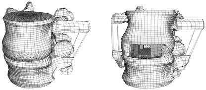
The intact finite-element model (left) and the model with cage (right)
To investigate the influence of the endplate on the load transfer, the inferior endplate of the L2 vertebra and the superior one of L3 were altered. No cartilaginous endplates were defined on the bony ones, as their effect on the load transfer was assumed to be negligible; furthermore, the cartilaginous endplate is usually removed prior to cage insertion. The shape of the bony endplates was in accordance with the reported observations [8, 31]. According to the published mean values, the endplate was modelled thicker adjacent to the annulus (0.85 mm) than in the central region (0.45 mm). The endplate material properties were varied in both models to represent a wide spectrum of bone qualities, ranging from the stiffness of the underlying cancellous bone up to that of cortical bone, i.e. 100, 600, 1000, 6000 and 12,000 MPa. Furthermore, alterations to the properties of the endplate correspond indirectly to the different techniques of endplate preparation. For example, setting the endplate modulus equal to that of the underlying cancellous bone (100 MPa) would be mechanically equivalent to surgical removal of the endplate. As, additionally, the strength has been shown to vary across the endplate [11], two non-homogeneous distributions of endplate properties were modelled: a rough distribution with four different moduli defined across the surface (Fig. 2), and a fine distribution for which the outer three "rings" of the rough distribution were further divided such that each ring of elements had a different property assigned.
Fig. 2.
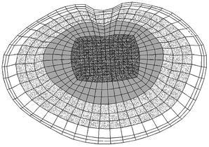
Rough distribution of endplate properties; each grey shade indicates another elastic modulus
Failure load and strength of endplates have been determined experimentally [11], but their relation to the elastic modulus of the structure is unknown. Therefore, two different variations were modelled, using the values of the moduli assigned in the homogeneous cases. For the "soft endplate", the modulus in the middle area (darkly shaded in Fig. 2) was the same as for cancellous bone—100 MPa—and roughly or finely increased to 1000 MPa—the endplate property of the "normal" model—in the outermost ring. This model may be considered equivalent to the case of partial endplate excision in the middle of the vertebra. In the model with a "hard endplate" a modulus of 1000 MPa was assigned to the middle area, and increased up to 12,000 MPa—similar to the cortical shell modulus—in the outermost ring. This model would probably represent the physiological situation most precisely. Nine different definitions of endplate properties were thus evaluated in the intact finite-element model and nine in the model with cage.
Gap elements were used for the contact interfaces between the cage and the endplate, with the contact direction being perpendicular to the cage surfaces. As most intervertebral implants have small teeth or serrations on the contact surfaces, a friction coefficient of 0.8 was defined between the cage and the adjacent endplates. The three possible translation components of the inferior surface of the L3 vertebra were fixed in space. As the loading conditions and the cage material were shown to have a minor influence on the load transfer compared to a cage insertion [29], a titanium implant was modelled and exclusively pure compression of 1000 N was applied to all models.
Results
Increasing the endplate modulus changed the von Mises stress distribution in the adjacent structures. The altered stress distribution in the cancellous bone of L3 for the intact models is shown in Fig. 3. Stress alterations mainly occurred in the regions directly adjacent to the endplate. The harder the endplate, the smaller the maximum stress in the trabecular bone was, as can be seen in the decreasing amount and size of black areas in Fig. 3 and in Fig. 4. Whether the elastic moduli were varied roughly or finely across the endplate had a negligible influence on the stress distribution in the cancellous bone; a similar result was seen. With a stiffer endplate, load is shifted from the cancellous core to the vertebral cortex.
Fig. 3.

Von Mises stress distributions for intact models under axial compression. A sagittal cut through the cancellous core of L3 is shown, anterior is to the left. The assigned endplate modulus is given in the bottom row
Fig. 4.
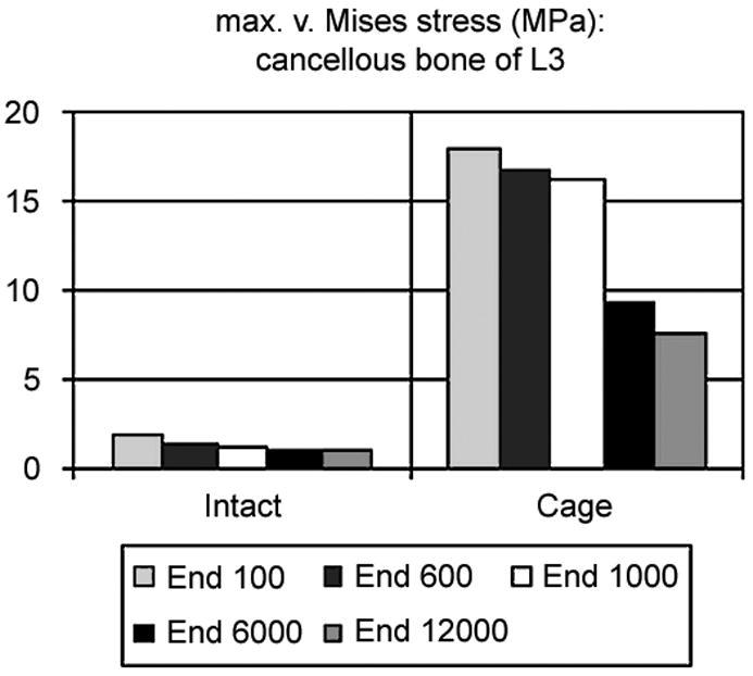
Maximum von Mises stress in the cancellous core of L3: on the left side in the intact case, on the right side in the models with cage. The corresponding endplate modulus is given in the legend
Due to the above-described findings, a representative subset of all solved models for the comparison of the intact case to the model with cage is presented to facilitate understanding. The results of models with a uniform endplate modulus of 100 MPa, i.e. similar to cancellous bone, 1000 MPa, the "normal" one, and 12,000 MPa, similar to cortical bone, are therefore presented along with the results of models with soft and hard endplates derived from the fine distribution of the moduli.
The maximum von Mises stress in the cancellous bone of L3 decreased with increasing endplate stiffness (Fig. 4). That was true in the intact cases as well as in the models with cage, but to a different degree. It is also clearly visible that the magnitude of the stress following cage insertion exceeded the stress in the intact case.
Inserting a cage altered the stress distribution in the FSU more than did the variation of the endplate modulus (Fig. 5, Fig. 6). The harder the endplate, the more the stress was concentrated in the contact areas between cage and bone. Whereas in the intact models the stress was slightly concentrated in the centre if the modulus was increased, it progressed deeper into the bodies in the peripheral areas if a cage was inserted.
Fig. 5.
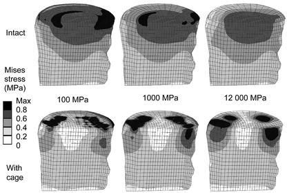
Von Mises stress distributions for intact cases (upper row) and models with a titanium cage (bottom row). A sagittal cut through the cancellous core of L3 is shown, anterior is to the left. The corresponding endplate modulus is given in the middle
Fig. 6.
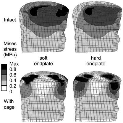
Von Mises stress distributions for intact cases (upper row) and models with a titanium cage (bottom row). A sagittal cut through the cancellous core of L3 is shown; anterior is to the left. The corresponding endplate definition is denoted in the middle, obtained with a fine distribution of the moduli
This finding was confirmed when the stress magnitudes were considered. Examples for the percentile differences of the stress maxima in the L3 vertebral body between an intact and a cage model due to varied endplate properties are depicted in Table 1. Results from discrete element subsets are presented. These element subsets A (anterior), B (middle), C (posterior) were lying in the sagittal plane of the vertebral body of L3. The locations below the central slot of the modelled implant, two element layers away from the endplate, were chosen to minimize possible artefacts resulting from contact force peaks. The redistribution of stresses towards the peripheral regions after cage insertion is apparent for all cases.
Table 1.
Percentages of the maximum von Mises stress in the subsets A (anterior), B (middle), C (posterior) in the sagittal plane of the lower vertebra due to varied endplate properties. The corresponding intact models were set to 100%
| Model with: | A | B | C |
|---|---|---|---|
| Endplate elastic modulus 100 MPa | 155 | 36 | 90 |
| Endplate elastic modulus 1000 MPa | 207 | 32 | 134 |
| Endplate elastic modulus 12,000 MPa | 212 | 36 | 165 |
| Soft endplate (100–1000 MPa) | 203 | 29 | 116 |
| Hard endplate (1000–12,000 MPa) | 214 | 33 | 150 |
The stress distribution in the endplate itself was altered due to the definition of a non-homogeneous material distribution, but these differences did not propagate further. Comparing the resulting stress distribution in the cancellous bone (Fig. 5, 6), for example, only minor differences could be detected that might be caused by this variation of the endplate properties. In all cases, increasing the endplate modulus led to more prominent changes in the stress values and distribution after cage insertion as compared to the intact case.
Discussion
The introduction of intervertebral cages for spinal fusion has been a promising innovation [1, 5, 18, 19, 28, 30]; nevertheless, there is ongoing debate regarding the necessary conditions as well as the criteria for successful fusion [21, 25, 36]. The presented work evaluated the influence of endplate material properties on the stress distribution in a lumbar FSU. Inserting a cage increased the stress and markedly altered the overall load transfer under all circumstances investigated. A harder endplate led to increased concentration of the stress peaks, and high stresses were propagated further into the vertebral body, into areas that would usually not experience similar stresses.
Although the presented finite-element models were based on physiological material properties and accurate spinal geometry, including ligaments, there were some limitations. For most materials, the corresponding property definitions were homogeneous. A more physiological material distribution in all structures may have produced different stress distributions. Nevertheless, non-uniform material distribution in finite-element models may also introduce numerical uncertainties.
The vertebral endplate and the underlying cancellous bone are known as preferential fracture locations in the vertebral body [8, 13, 14, 37], and subsidence of interbody fusion constructs in adjacent endplates is a frequent mode of failure [7, 11, 15, 16, 21, 35]. Nevertheless, whereas the cancellous bone of the vertebra has been the subject of numerous studies [17, 22, 23, 24, 26, 27], the literature concerning the vertebral endplate is comparatively sparse. Wenger et al. [38] evaluated the mechanical properties of the osseous endplate in bending and tension, reporting differences in material properties between normal and diseased specimens. This variation could not be attributed to differences in bone mineral density (BMD) [39]. In the frontal plane the BMD was described to be higher at the periphery and lowest in the middle of the endplate. Variation of endplate thickness has been reported, with the anterior and the posterior regions being thicker than the central part [8, 31]. Grant et al. [11] determined highly significant regional strength and stiffness differences in the lumbar and sacral endplates, with the centre of the endplate being the weakest region. These variations were included in some of the presented models, but the varied endplate properties only altered the stress distribution in the endplate itself. It did not cause observable changes in the adjacent structures. Therefore, the definition of a single elastic modulus for the entire endplate seems to be justified for general analyses concerning the behaviour of a complete FSU. Investigations of fracture patterns in the endplate and the vertebral body, for example, would in contrast require a more detailed and appropriate definition.
The consequences of complete and partial endplate excision, as well as endplate preservation, can be inferred from these finite-element models. For the flat-interface monobloc cage type investigated, contact pressure was found to be concentrated around the edges of the implant, producing stress concentrations that could probably be tolerated by this strong part of the endplate. In contrast, reliance of this implant on cancellous bone, after endplate removal, may present an increased risk of cage subsidence. The strength of the vertebra–cage interface is not influenced by the endplate alone, but also by the properties of the underlying bone. It has been assumed that the centre of the vertebral body is weaker than the periphery, which is supported by the fact that the distance between trabeculae increases in the vertebral centre [11]. Nevertheless, only a few biomechanical studies have been conducted to evaluate the regional differences in the vertebral body and their influence on its strength. Antonacci et al. [2] showed the bone density in the anterior region of the vertebral body to be higher than in other regions, regardless of overall density. In contrast, Banse et al. [3] reported the cancellous bone density to be higher in core samples from the posterior region than in those obtained anteriorly or laterally. The central area of the vertebral body was not explicitly evaluated in either study; however, Edwards et al. have reported the centre of the endplate to be more porous [8]. In this study, a second continuous layer of dense bone was observed adjacent to the endplate in many lumbar vertebrae examined in the midsagittal plane. It is unclear why this structural feature was not seen in all vertebrae, or how it might affect stiffness and strength. In general, more literature concerning structural variations can be found than studies assessing the regional differences of strength and stiffness. This makes it difficult if not impossible to provide a complete picture of the dangers and failure probabilities due to cage insertions. Nevertheless, it can be concluded that placement of implants in the central area of the vertebral body could cause early failure. For the investigated implant shape, in contrast, contact between the cage and the endplates was concentrated at the periphery of the cage.
Using physiological finite-element models of an FSU enabled the assessment of the influence of endplate material and its distribution on the stresses in the vertebrae. By calculating the stress distribution for the entire motion segment, it was demonstrated how much the overall stresses are affected by cage insertion. These changes cannot be assessed with experimental methods except at discrete locations [9]. In addition, the variability resulting from different cadaver specimens used in experimental studies was removed. The alteration of the load transfer is likely to cause structural changes in the adjacent bone. These changes may offer an explanation for the damage occurring to the underlying bone, as well as for the subsequent subsidence of the cage. Nevertheless, they also offer the possibility of adaptation to the new loading pattern.
Conclusion
The distinction between failure and success of fusion is influenced by a number of different parameters. Cage insertion was shown to change the overall load transfer under static loads, whereby the material properties of the cancellous bone and the endplate were found to be more important factors for the resulting stress than the cage material or the loading conditions [29]. Summarising our previous work in this area, it can be concluded that cages should be designed such that they rely on the strong peripheral part of the endplate to reduce the risk of subsidence, and additionally offer a large volume for the bone graft and a big area for the interface between the graft and the bleeding bone in the middle. Furthermore, care should be taken to confirm that the neighbouring vertebral bodies show sufficient bone density in the peripheral regions, so that the altered load transfer following cage insertion can be supported until the remodelling process produces an adequate adaptation to the new loading situation.
Acknowledgements
The authors thank Dr. Qingmao Hu for assistance with the segmentation of the CT slices.
References
- 1.Agazzi J Neurosurg. 1999;91:186. doi: 10.3171/spi.1999.91.2.0186. [DOI] [PubMed] [Google Scholar]
- 2.Antonacci Spine. 1997;22:2393. doi: 10.1097/00007632-199710150-00014. [DOI] [PubMed] [Google Scholar]
- 3.Banse Bone. 2001;28:563. doi: 10.1016/S8756-3282(01)00425-2. [DOI] [PubMed] [Google Scholar]
- 4.Boden Spine. 1995;20:102S. [PubMed] [Google Scholar]
- 5.Brantigan Spine. 2000;25:1437. doi: 10.1097/00007632-200006010-00017. [DOI] [PubMed] [Google Scholar]
- 6.Closkey Spine. 1993;18:1011. doi: 10.1097/00007632-199306150-00010. [DOI] [PubMed] [Google Scholar]
- 7.Diedrich J Spinal Disord. 2001;14:522. doi: 10.1097/00002517-200112000-00012. [DOI] [PubMed] [Google Scholar]
- 8.Edwards Spine. 2001;26:218. doi: 10.1097/00007632-200101150-00019. [DOI] [PubMed] [Google Scholar]
- 9.Frei Spine. 2001;26:2080. doi: 10.1097/00007632-200110010-00007. [DOI] [PubMed] [Google Scholar]
- 10.Goel Spine. 1993;18:1531. [PubMed] [Google Scholar]
- 11.GrantSpine 20012688911317111 [Google Scholar]
- 12.Hollowell J, Vollmer D, Wilson C, Pintar F, Yoganandan N (1996) Biomechanical analysis of thoracolumbar interbody constructs. How important is the endplate? Spine 21:1032–1036 [DOI] [PubMed]
- 13.HolmesSpine 1993181288434313 [Google Scholar]
- 14.Ikeuchi J Orthop Sci. 2001;6:39. doi: 10.1007/s007760170023. [DOI] [PubMed] [Google Scholar]
- 15.JostEur Spine J 199871329629937 [Google Scholar]
- 16.Kettler J Neurosurg. 2000;92:87. doi: 10.3171/spi.2000.92.1.0087. [DOI] [PubMed] [Google Scholar]
- 17.Kothari Bone. 1998;22:437. doi: 10.1016/S8756-3282(98)00031-3. [DOI] [PubMed] [Google Scholar]
- 18.Kuslich Spine. 1998;23:1267. doi: 10.1097/00007632-199806010-00019. [DOI] [PubMed] [Google Scholar]
- 19.Kuslich Spine. 2000;25:2656. doi: 10.1097/00007632-200010150-00018. [DOI] [PubMed] [Google Scholar]
- 20.Lu Spine. 1996;21:2570. doi: 10.1097/00007632-199611150-00006. [DOI] [PubMed] [Google Scholar]
- 21.McAfee J Bone Joint Surg Am. 1999;81:859. doi: 10.2106/00004623-199906000-00014. [DOI] [PubMed] [Google Scholar]
- 22.Millard Calcif Tissue Int. 1998;63:482. doi: 10.1007/s002239900562. [DOI] [PubMed] [Google Scholar]
- 23.Mosekilde Calcif Tissue Int. 1993;53:S121. doi: 10.1007/BF01673420. [DOI] [PubMed] [Google Scholar]
- 24.Mosekilde Bone. 1987;8:79. doi: 10.1016/8756-3282(87)90074-3. [DOI] [PubMed] [Google Scholar]
- 25.Mulholland Eur Spine J. 2000;9:S110. doi: 10.1007/PL00008314. [DOI] [PMC free article] [PubMed] [Google Scholar]
- 26.Odgaard Bone. 1997;20:315. doi: 10.1016/S8756-3282(97)00007-0. [DOI] [PubMed] [Google Scholar]
- 27.Overaker J Biomech Eng. 1999;121:542. doi: 10.1115/1.2835085. [DOI] [PubMed] [Google Scholar]
- 28.PavlovEur Spine J 2000922410905441 [Google Scholar]
- 29.Polikeit Factors influencing stresses in the lumbar spine after the insertion of intervertebral. 2002;cages:finite. doi: 10.1007/s00586-002-0505-8. [DOI] [PMC free article] [PubMed] [Google Scholar]
- 30.Ray Spine. 1997;22:667. doi: 10.1097/00007632-199703150-00019. [DOI] [PubMed] [Google Scholar]
- 31.Roberts S, McCall I, Menage J, Haddaway M, Eisenstein S (1997) Does the thickness of the vertebral subchondral bone reflect the composition of the intervertebral disc? Eur Spine J 6:385–389 [DOI] [PMC free article] [PubMed]
- 32.Shirazi-Adl Spine. 1984;9:120. doi: 10.1097/00007632-198403000-00003. [DOI] [PubMed] [Google Scholar]
- 33.Shirazi-Adl Spine. 1986;11:914. doi: 10.1097/00007632-198611000-00012. [DOI] [PubMed] [Google Scholar]
- 34.Silva Spine. 1997;22:140. doi: 10.1097/00007632-199701150-00004. [DOI] [PubMed] [Google Scholar]
- 35.Steffen Spine. 2000;25:1077. doi: 10.1097/00007632-200005010-00007. [DOI] [PubMed] [Google Scholar]
- 36.Steffen T, Tsantrizos A, Fruth I, Aebi M (2000) Cages: designs and concepts. Eur Spine J 9 [Suppl 1]:S89–S94 [DOI] [PMC free article] [PubMed]
- 37.van Clin Biomech. 2001;16:S135. doi: 10.1016/S0268-0033(00)00105-4. [DOI] [PubMed] [Google Scholar]
- 38.Wenger KH, Wilke H-J, Pross A, Claes LE (1997) Mechanical and ultrastructural properties of the osseous vertebral endplate. Annual report of the Institut für Unfallchirurgische Forschung und Biomechanik, Ulm
- 39.Wenger Bone mineral density of the vertebral. 1999;endplate:an. [Google Scholar]


