Abstract
We present an adaptive optics spectral domain optical coherence tomography (AO-SDOCT) with a long focal range by active phase modulation of the pupil. A long focal range is achieved by introducing AO-controlled third-order spherical aberration (SA). The property of SA and its effects on focal range are investigated in detail using the Huygens-Fresnel principle, beam profile measurement and OCT imaging of a phantom. The results indicate that the focal range is extended by applying SA, and the direction of extension can be controlled by the sign of applied SA. Finally, we demonstrated in vivo human retinal imaging by altering the applied SA.
OCIS codes: (170.4500) Optical coherence tomography, (110.1080) Active or adaptive optics, (170.4470) Ophthalmology
1. Introduction
Optical coherence tomography (OCT) provides cross-sectional imaging of the internal microstructures of biological tissues [1]. It is a powerful imaging technique, especially in ophthalmology [2–6]. Among several implementations of OCT, spectral domain OCT (SDOCT) provides high resolution, high sensitivity and high speed imaging [7–10]. Such implementations enable visualization of the microstructures of the human eye by non-invasive and non-contact measurement. High sensitivity of OCT detection enables imaging of structures with very low optical scattering, such as the retina. The high axial and lateral resolution enables the precise morphological investigation of retinal pathologies. Axial resolution is proportional to with being the center wavelength and being the spectral bandwidth of the light source. However, lateral resolution is linked to the focusing property of the illumination on the sample. The lateral resolution at the focal plane is proportional to the inverse of numerical aperture (NA) if there is no aberration.
For high-resolution retinal imaging, the lateral resolution can be improved by using higher NA illumination, which is typically realized by enlarging the probe beam diameter on the cornea. However, the aberrations of the anterior part of the eye increase with the incident beam diameter. Ocular aberration deteriorates lateral resolution and leads to reduced image quality [11,12], so it is not possible to achieve diffraction limited resolution of a few micrometers without correction of ocular aberrations. Therefore, correction of ocular aberration is essential for cellular level retinal imaging.
Adaptive optics (AO) technology has been used to solve this problem. Ocular aberration can be corrected dynamically by using AO [13–16]. AO has been combined with several type of ophthalmic imaging modalities such as a flood-illumination camera [13,15,17,18], a scanning laser ophthalmoscope (SLO) [19–21], and an OCT [22–27]. By using these techniques, in vivo cellular level investigation of retinal disorders and functions has also been demonstrated [28,29]. Thus, these AO retinal imaging devices have provided improved lateral resolution.
However, a larger probe beam diameter leads to rapid degradation of lateral resolution in the axial direction because the depth of focus (DOF) shortens with the square of NA. There is a trade-off between lateral resolution and DOF, and a short DOF is problematic for in vivo AO-OCT imaging of human retina. For instance, there is temporal wavefront instability in the form of micro-fluctuations of accommodation [16,30], tear films, a point scanning system aberration, involuntary eye motion, and some other factors. Regardless of AO dynamic aberration correction, the temporal fluctuations remain due to the limited closed-loop bandwidth up to 1–2 Hz [16]. These variations make it difficult to maintain perfectly in-focus imaging conditions during measurement and deteriorate retinal image quality. Hence, AO retinal imaging necessitates the precise defocus adjustment by monitoring the en face projections or optimized post-processing. In addition, especially for the OCT retinal imaging, the retina and choroid have thick multi-layered structures with a thickness of around 0.6 mm, and hence a long focal range is required. In practice, the DOF of typical AO system is less than 100 µm, this is too narrow to image all of retinal and choroidal layers. Hence, it is important to achieve a long focal range while preserving high lateral resolution.
The extended DOF while preserving the lateral resolution and energy efficiency have been studied in the fields of vision and optical imaging [31]. For instance, in the field of vision, the extended DOF is a common topic for the correction of presbyopia. Specifically, the multifocal lenses have been used to have a long focal range. Although some technical or physiological issues are still remained, the improvement of near vision to monofocal lenses has been observed [31–34]. On the other hands, in the field of microscopy, three-dimensional scanning method and the point spread function engineering by using wavefront coding [35], axicon lenses [36], and annular illumination [37] have been proposed to extend the DOF more efficiently. Similarly, in the field of OCT, dynamic focusing during T-scan OCT detection has been presented and has successfully shown retinal microstructures [38]. Another approach is the Bessel illumination method which uses an axicon lens [39,40]. Although the image quality of this method is excellent, Bessel illumination has low light efficiency, which makes it inappropriate for retinal imaging.
It is noteworthy that the axicon can be considered to generate extremely high-order spherical aberration (SA) [41]. Several authors have shown the effect of extension of DOF by SA in the field of laser applications [42–44]. And hence, we hypothesize that the SA of standard orders would extend the DOF of AO-OCT imaging.
In this paper, we demonstrate high-resolution volumetric imaging of retinal microstructures by means of extended DOF, which is achieved by introducing a controlled SA. A custom-built AO-SDOCT is utilized for the imaging. In this system, eye aberration is dynamically corrected by AO, and additional controlled SA is introduced also by AO in order to achieve the extended DOF. Namely, by using AO, we create phase distribution of SA on the pupil plane in addition to cancelation of ocular aberration. The imaging properties of this method are also investigated in detail, applying the Huygens-Fresnel principle, beam profile measurement, and OCT imaging of a phantom.
2. System
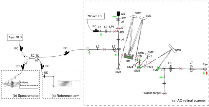
The schematic diagram of AO-SDOCT is shown in Fig. 1 . The system is based on our previously published custom-built AO-SDOCT [27]. This AO-SDOCT consists of two subsystems of SDOCT and AO. The details of these subsystems are described in the following sections.
Fig. 1.
The schematic diagram of the optical setup of AO-SDOCT. PC: Polarization controller, FC: Fiber coupler, (a) The optical setup of the AO retinal scanner, L#: Lenses, LP#: Linear polarizers, D: Dichroic mirror, Ach: Achromatizer, ST: Stop, SM#: Spherical mirrors, FM#: Flat mirrors, WS: Wavefront sensor, DM: Deformable mirror, VS: Vertical galvanometric scanner, HS: Horizontal galvanometric scanner. (b) Spectrometer. (c) Reference arm, ND: neutral density filter. The green bars and arrows indicate the optical conjugate planes of the pupil, and the red crosses and arrow indicate the optical conjugate planes of the retina.
2.1. Spectral domain optical coherence tomography
The SDOCT subsystem uses an SLD light source (Superlum diode, Ireland) with 1.02-µm center wavelength and a spectral bandwidth (FWHM) of 106 nm. The theoretical axial resolution is 4.7 µm in air and 3.4 µm in tissue. Light from the source is divided and delivered to a sample arm and a reference arm by a 50/50 fiber coupler. In the sample arm, light is delivered to the retina via an AO retinal scanner. Backscattered light from the retina is recoupled into the fiber and sent back to the fiber coupler, where the backscattered sample beam is recombined with the light from the reference arm. The recombined light is delivered to the spectrometer, in which the light is collimated by an achromatic lens (AC254-050-B, Thorlabs Inc., NJ), diffracted by a reflective grating (GR50-1210, 1200 lp/mm, Thorlabs) and focused by a lens pair (AC508-050-B and AC508-150-B, Thorlabs) on an InGaAs 1024-pixel line-scan camera driven at a line rate of 91,911 lines/s (SUI1024LDH, Sensors Unlimited Inc., NJ).
The sensitivity of the system was measured to be 81.5 dB with a sample power of 1.26 mW. Sensitivity was measured with a cat's eye consisting of an achromatic doublet (AC254-060-B, Thorlabs) and a mirror at an optical conjugated plane of the retina. Note that during this measurement the deformable mirror of the AO retinal scanner was flattened and system aberration was not corrected. Because we put the mirror (reflector) as a sample, it is impossible to correct the system aberrations with this double pass configuration. This could result in underestimation of the sensitivity. Alternatively, we also measured the sensitivity with aberration correction by an indirect method as follows. First, the system aberration was corrected with a model eye using a paper (scattering target) as a retina. Second, we replace the paper to a mirror (reflector) and realigned it. The defocus and tilts were adjusted to have the maximum re-coupling efficiency to the optical fiber of the interferometer. Finally, the sensitivity was measured. As a result, the sensitivity with aberration correction was 85.9 dB, which is 4.4 dB larger than the sensitivity without the aberration correction.
The optical design of the system ensures a beam diameter of 7.4 mm on the cornea, and it results in a transform limited 1/e2 beam width of 2.9 µm on the retina. The DOF, which is defined by 2-times Rayleigh length, was 48 µm.
2.2. Adaptive optics
2.2.1. Adaptive optics retinal scanner
The AO subsystem is based on our previously built AO retinal scanner [45]. In this paper we used it for canceling ocular aberration and creating SA. First, a large defocus was corrected by a Badal optometer which is placed before the eye pupil (L6 and L7). Then, the residual aberrations are measured by a Shack-Hartmann wavefront sensor (HASO32, Imagine Eyes, Orsay, France) using a laser diode with a 700-nm center wavelength as a beacon. A magnetic deformable mirror (Mirao52, Imagine Eyes) corrects the measured aberrations. An eye pupil, a deformable mirror, a wavefront sensor and two scanners are optically conjugated to each other by the off-axis reflective telescopes and Badal optometer.
To cancel longitudinal chromatic aberrations of human eye, a custom-designed broadband achromatizer is used. The general concept of an achromatizer is described by Fernández et al. [46]. With this achromatizer, the axial chromatic focal shift was controlled to be less than 3 µm in the wavelength band of 970 to 1070 nm. The achromatizer is located between the input collimator and a dichroic mirror which splits a back-scattered sample beam to the fiber tip and to a wavefront sensor. This configuration prevents surface reflections from the achromatizer.
The AO control software was implemented using LabVIEW SDK (Imagine Eyes). The influence matrix is obtained by placing a single mode fiber at the optical conjugate plane of the retina. The iteration frequency of the AO closed loop was around 10 Hz.
The retina is scanned with a vertical-fast raster scanning protocol using two galvanometric scanners in which the slow scan is in the horizontal plane and the fast scan is in the vertical plane. The optical loss of the AO retinal scanner is 2.8 dB for a single pass.
2.2.2. Adaptive optics-control with arbitrary target aberration
For dynamic ocular aberration correction, a deformable mirror applies counter aberration to the illumination wavefront based on the measured wavefront. The closed loop control algorithm is the vital link between these two components; the measured wavefront and the wavefront created by the deformable mirror. In AO closed loop operation, integral controller is applied. A command vector, a set of control voltages to the electrodes of the deformable mirror, at the time point of t + T was obtained as [47]
| (1) |
where t is time, T is a time period of a single cycle of the AO closed loop, and is a command vector of the one-previous cycle. is a slope vector obtained by the Shack-Hartmann wavefront sensor and A is the Moore-Penrose pseudo inverse matrix of the influence matrix of the AO-setup A, and α represent a closed-loop gain. To add an arbitrary aberration to the target of AO closed-loop control, Eq. (1) is extended and we subtract the target slope vector from the measured slope vector,
| (2) |
where is a target slope vector defined from the target aberration as . is a vector of the Zernike coefficients of the target aberration and Z is a conversion matrix from the Zernike coefficient vector to a slope vector. In this paper, we used root mean square (RMS) value to represent the Zernike coefficients, which are normalized by a pupil diameter, 7.4 mm.
Since our AO control algorithm defines the command vector by Eq. (2), the wavefront at the pupil converges to the target aberration by the closed-loop operation. In this study, we set a proper amount of SA as the target.
3. Pseudo focal shift by introducing spherical aberration
3.1. Theory
In this study, we introduced SA to extend the focal range of AO-SDOCT. In the presence of SA, a paraxial focal point and a marginal focal point are no longer identical, i.e., SA generates longitudinal aberration (LA). This LA results in not only the axial extension of the focus but also the shifting of the pseudo focal plane as discussed below. LA is given using the following equation [48]:
| (3) |
where f/# is the f-number, and is the third-order SA coefficient of Seidel aberration. Conversion from Zernike to Seidel representation is given by [49]
| (4) |
where is the third-order SA coefficient of Zernike aberration.
In addition to the focus extension, the LA also shifts the depth position of the focus. Namely, under the presence of LA, the highest lateral resolution is no longer obtained at the paraxial focal plane. According to geometrical optics, the depth location of a minimum circle, where the marginal ray crosses a caustic, is regarded as one of the best image plane. The minimum circle position is located at the position distant from the paraxial focus point for 0.75 LA, in the direction of the marginal focus point [48]. However, in a numerical simulation based on the Huygens-Fresnel principle in Zemax, we found that the minimum circle was no longer located at 0.75 LA, and it was located at 0.25 LA.
Here, we defined positive and negative SAs as follows. If the marginal rays are more highly refracted than the paraxial rays, we denote it positive SA, and vice versa. Thus, positive SA shifts the depth position of the minimum circle to get closer to the lens, while negative SA shifts the minimum circle position to get away from the lens. In this study, an additional defocus is added to the target aberration in order to cancel this pseudo focal shift incurred by the shift of the minimum circle. In this paper, we call this additional defocus “counter defocus.”
Aside from this counter defocus, we have to apply the defocus to cancel a longitudinal chromatic aberration (LCA) between the 1-µm probe and 700-nm beacon beam. In practice, we canceled the LCA by adjusting the distance between the relay lens in front of the wavefront sensor (L4 and L5). However, this cancellation could not be perfect because of practical implementation issues. The amount of defocus needed to cancel the residual LCA is about –0.2 µm. In this study, we applied the sum of the counter defocus and the defocus to cancel the residual LCA.
3.2. Estimation of counter defocus
The counter defocus was estimated and the relevance of the estimation was confirmed by an experiment.
We set arbitrarily and the corresponding pseudo focal shift was obtained by the numerical simulation using Zemax (Radiant Zemax, WA). Subsequently, the theoretical prediction of the counter defocus was calculated by the following equation [49]:
| (5) |
where is the pseudo focal shift from the focal plane, c is dioptric power, n is the refractive index, R is pupil radius, and is the Zernike coefficient of defocus. Here, corresponds to 0.25 LA.
In practical estimation, a lens with a 16-mm focal length was assumed as a model of a human eye. A beam radius of 3.7 mm is assumed. The SA under consideration ranged from –1.0 µm to 1.0 µm with a 0.1-µm step.
3.3. Experimental validation
The experiment was done by using a model eye, comprised of a lens with a focal length of 16 mm and a paper target which mimicked the refractive optics of the eye (cornea and crystalline lens) and retina. In this experiment, the counter defocus was defined as the defocus which maximized the OCT intensity of the paper of the model eye. Then, the counter defocus was estimated for each SA by controlling the target wavefront in the AO closed loop.
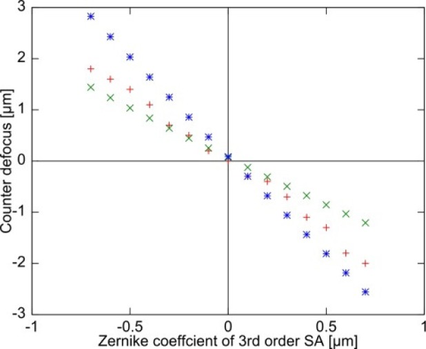
Figure 2 shows the counter defocus as a function of SA. It should be noted that the defocus offset incurred by LCA has been corrected in this plot.
Fig. 2.
The counter defocus of ray tracing simulation and experiment are plotted as a function of Zernike coefficient of third-order SA where + is for experiment, × is for simulation-1, and * is for simulation-2.
The results of simulation-1 were obtained by the numerical simulation and indicate the amount of counter defocus required to shift the position of the minimum circle to the focal plane, which corresponds to the distance of 0.25 LA. Contrastingly, simulation-2 is the amount of defocus required to shift the paraxial focus position to the focal plane.
This experiment and the two simulation results indicate that the actual best image plane is located between the paraxial focus position and the position of the minimum circle. A small discrepancy between simulation-1 and the experiment can be considered to come from a difference between the actual beam intensity distribution on the pupil plane and that assumed in the simulation. Here, we assumed a Gaussian distribution.
4. System performance
Theoretically, the peak signals will decrease as a function of applied SA. At the same time, residual RMS wavefront error will increase because of an inevitable property of our AO-control algorithm; large target aberration results in unavoidable large RMS error (see Appendix A).
In order to evaluate the performance, we measured the maximum OCT signals and the RMS wavefront error as altering the applied SA. The counter defocus and LCA cancelation was done based on the strategy described in Section 3. The same model eye used in the Subsection 3.3 was employed, and the backscattered light from the thin paper target was recorded by OCT. The maximum OCT signal was defined as the average of maximum signals of 100 A-lines. The residual RMS wavefront errors were recorded by the wavefront sensor. The SA under consideration ranged from –1 µm to +1 µm with 0.1-µm step.
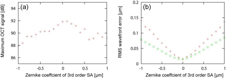
The maximum OCT signals are plotted as a function of applied SA, as shown in Fig. 3(a) . The maximum OCT signal was found at SA of around 0.0 to 0.1 µm. The possible reason of the tiny positive shift would be the system induced spherical aberration originated from the detection path and/or wavelength differences between the probe and beacon beams.
Fig. 3.
The maximum OCT singals for each SA is shown in (a). The RMS wavefront errors for each SA is shown in (b). The‘+ and × indicate the experimental and simulation results, respectively.
The residual RMS error was increased as a function of the amount of applied SA, as shown in Fig. 3(b). Numerical simulation results showed the similar tendency with the experimental results. The discrepancy between the experiment and simulation would be explained by measurement error which did not take into account in the simulation (see Appendix A).
5. Extension of depth-of-focus by introducing controlled aberration
In order to quantitatively investigate the effect of third-order SA on extension of focal range, we evaluated the lateral resolution along the depth. The lateral resolution and DOF were evaluated based on the depth-resolved point spread function (PSF) obtained by a numerical simulation and beam profiler measurement in an experiment.
5.1. Methods
A scanning slit optical beam profiler (BP104-IR: Thorlabs) was employed in this study. However, the slit size is 2.5 µm, and the minimum measureable diameter for this beam profiler is 10 µm, which is significantly larger than the transform limited spot size of our standard model eye, 6.6 µm. Hence, we utilized another eye model with a lens with 30-mm focal length (AC127-030-B: Thorlabs) as an alternative. This model eye was also utilized for the ray tracing and experiment.
We numerically simulated the PSFs for SA = +0.7, 0.0, and –0.7 µm by using Zemax. The counter defocus was defined by Eq. (5) in Section 3. We calculated the theoretical depth-resolved PSF at each depth over ±1000 µm, where the beam diameter reaches a minimum at the depth of 0 µm. PSF was calculated based on the Huygens-Fresnel principle in Zemax. We set the pupil and image sampling sizes at 256 pix × 256 pix. The lateral spacing of the simulation was set at 0.5 µm, and the result was binned to have the same resolution with the experiment of 1.2 µm. We calculated the incoherent sum of the PSF at 5 different wavelengths of 967 nm, 993 nm, 1020 nm, 1046 nm and 1073 nm which were adopted as representative wavelengths of the broad band light source of a probe beam. The PSFs were not normalized. The lateral resolution of the system was defined by 1/e2 beam width. The DOF was defined by the FWHM of central peak intensity profile along the depth.
In the experiment, we measured the intensity profile by the beam profiler at each depth. We set a target resolution at 1.2 µm. Note that intensity profile represents the integrated profile over the entire slit, and it is different from the simulation. After the acquisition, the measured intensity profiles were normalized at each depth location by the maximum intensity. This is because there was a significant intensity fluctuation by a rotational slit profiler at each depth. Then, we plotted the entire profiles for SA = +0.7, 0.0, and –0.7 µm. The measurement range was ±1000 µm with a 20-µm step, and the 0-µm depth was set so that the beam diameter reaches a minimum at this depth. The counter defocus obtained by another experiment similar to Section 3 was also added for this measurement. Note that, although the counter defocus utilized in the simulation and the experiment are not perfectly identical due to the difference of intensity distribution on the pupil plane as mentioned in Section 3, this only results in a difference in the depth-offset and has no significant effect on the results. The lateral resolution was defined by beam width. The variation of the lateral resolution as a function of the depth was then fitted to the following function [50] which is parameterized by , and :
| (6) |
where is the minimum lateral resolution, z is depth position, is depth position with the minimum lateral resolution, and is the Rayleigh length. is used as a parameter to assess the focal range.
5.2. Results
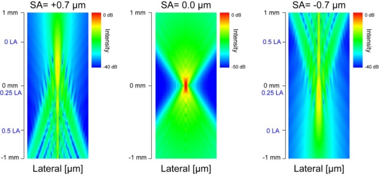
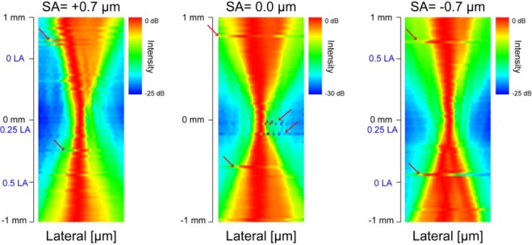
The depth-resolved PSFs for SA = +0.7, 0.0, and –0.7 µm obtained by Zemax are shown in Fig. 4 . The profile of PSF of the case of SA = 0.0 µm (without SA) was almost symmetric with respect to the focal plane. However, the depth profile of the PSF becomes asymmetric when SA was applied. When positive SA was applied, the transversal width of PSF was smaller at closer to the lens than farer from the lens, although some side peaks appeared. When negative SA was applied, the transversal width of PSF became smaller at farer from the lens than closer to the lens, and at the same time side peaks appeared. The DOFs are 515 µm, 125 µm, and 489 µm for SA = +0.7, 0.0, and –0.7 µm, respectively. The DOF was extended 4 times with SAs. The 1/e2 beam widths are 12.6 µm, 7.66 µm, and 12.4 µm for SA = +0.7, 0.0, and –0.7 µm, respectively. The lateral resolution becomes worse 1.6 times with SAs.
Fig. 4.
Theoretical PSFs for SA = +0.7, 0.0, and –0.7 µm. The depth positions of LA are indicated by blue-letters.
If we simply reduce the beam diameter to have an m-times longer DOF, we should shrink the beam diameter in times. And hence, the lateral resolution is reduced in m times worse. Here, to have the same 4 times longer DOF, the lateral resolution should decrease in 2 times. It means that the lateral resolution is 1.25 times better with SA with the same DOF.
The measured intensity profiles for SA = +0.7, 0.0, and –0.7 µm are shown in Fig. 5 . For all SA values, the intensity profile was deteriorated and transversal width became larger as a function of depth with respect to the focal plane. The intensity profiles were not cylindrically symmetric although applied SA and defocus were symmetric. The possible reasons for this asymmetry are residual aberrations and the heterogeneity of the Gaussian distribution of the beam intensity on the pupil plane. Note that the abrupt translation of the beam indicated by the red arrows comes from the instability of the rotational slits of the beam profiler. Hence it is an artifact and can be safely ignored.
Fig. 5.
Normalized intensity profiles for SA = +0.7, 0.0, and –0.7 µm, which were obtained by the scanning slit optical beam profiler. Red arrows indicate the profile translations caused by instability of rotation scanning slits. The depth positions of LA are indicated by blue-letters.
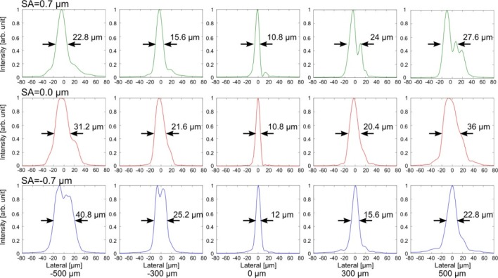
In order to see more clear differences, we compared the transversal intensity profiles in cross section at several depths, as shown in Fig. 6 . When positive SA was applied, the transversal width of intensity profile was smaller at closer to the lens. When negative SA was applied, the transversal width of intensity profile was smaller at father from the lens. The estimated were 172 µm, 126 µm, and 173 µm for SA = +0.7, 0.0, and –0.7 µm, respectively. The DOF was extended 1.4 times with SAs. Both of positive and negative SAs showed the extension of focal range. The minimum lateral resolutions were 16.6 µm, 14.2 µm, and 16.2 µm for SA = +0.7, 0.0, and –0.7 µm, respectively. The lateral resolution would become worse 1.2 times with SAs.
Fig. 6.
Normalized intensity profiles for SA = +0.7, 0.0, and –0.7 µm in linear scale. The Black arrows and numbers indicate the full width at half-maximum (FWHM).
These results indicate first that the effective focal range can be extended by applying SA. Second, lateral resolution was well preserved with SAs.
6. Phantom imaging
In this section, the extended focal range induced by SA is quantitatively evaluated by imaging a phantom. The OCT signal intensity, the lateral resolution and DOF were evaluated by an OCT phantom images and the numerical simulation.
6.1. Methods
In this experiment, a custom made phantom is imaged by AO-SDOCT. The phantom predominantly consists of agar gel. Polystyrene micro-beads with a 1-µm diameter (Polybead Polystyrene Microsphere 1.00 µm, Polysciences Inc.) are dispersed in the gel with a concentration of 91 million-beads/ml. The phantom is put on a paper and set at the retinal position of our model eye with its lens of 16-mm focal length. The paper is used as a reference plane in order to provide sufficient backscattering for wavefront sensing.
Phantom imaging was performed with a 0.8 degree (1024 A-line) scanning size, and 64 OCT B-scans were obtained at the same location on the phantom. The lateral resolution was estimated by measuring the bead size of the OCT B-scan images, as demonstrated by Leitgeb et al. [40] or Ralston et al. [51]. Applied SA was from –1.0 µm to 1.0 µm with a 0.1-µm step. For the defocus correction, we applied the sum of counter defocus and the defocus to cancel residual LCA, where the counter defocus was estimated by the method which is described in Subsection 3.3. In addition, we applied an additional 2.0-µm defocus. This was in order to shift the minimum circle from the paper plane, which is the reference plane of the wavefront sensing, to the inside of phantom. The applied SA and defocus are summarized in Table 1 .
Table1. Applied SA and defocus in phantom imaging.
| SA (µm) | –1.0 | –0.9 | –0.8 | –0.7 | –0.6 | –0.5 | –0.4 | –0.3 | –0.2 | –0.1 | |
| Defocus (µm) | 4.3 | 4.0 | 3.8 | 3.6 | 3.4 | 3.2 | 2.9 | 2.5 | 2.3 | 2.0 | |
| SA (µm) | 0 | 0.1 | 0.2 | 0.3 | 0.4 | 0.5 | 0.6 | 0.7 | 0.8 | 0.9 | 1.0 |
| Defocus (µm) | 1.8 | 1.5 | 1.4 | 1.1 | 0.7 | 0.5 | 0 | –0.2 | –0.34 | –0.6 | –0.86 |
After taking OCT images, each micro-bead was selected from 64 OCT B-scan images which have a maximum SNR of larger than 17 dB, and the lateral image size of the micro-bead was estimated. By selecting the micro-bead with large SNR, we excluded the micro-beads which were illuminated only at their periphery and were causing the error in the subsequent analysis. The lateral profile of micro-bead was fitted to a Gaussian function, and 1/e2 width of the Gaussian is calculated for all 64 OCT B-scan images. The average of 64 1/e2 widths was utilized to define the lateral resolution. To assess the DOF, the variation of the averaged width as a function of the depth was then fitted to Eq. (6), which is parameterized by , , and
In the numerical simulation, we calculated the PSFs by using Zemax. The method is similar to Section 5. The model eye with its lens of 16-mm focal length was used. Then, the theoretical DOF and the lateral resolution were estimated.
6.2. Results
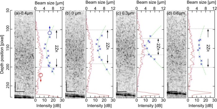
The OCT images of the phantom with several SAs are shown in Fig. 7 . It was found that, the tightest focus appeared at the SA of +0.3 µm. The reason of this positive shift is discussed in Subsection 8.1. Note that images with SA of from –0.5 µm to –1.0 µm were not correctly obtained because of vignetting at a spatial filter in the wavefront sensing arm.
Fig. 7.
Phantom images. The numbers in each images are the Zernike coefficients of applied SA. Reference planes for wavefront sensing are shown in the bottom side of the images. The black bars indicate 100 µm.
The variation of the lateral resolution and OCT signal intensity as functions of depth is shown in Fig. 8(a) (with –0.4-µm SA), (b) (without SA), (c) (with +0.3-µm SA), and (d) (with +0.6-µm SA). In addition, the averaged intensity profile, micro beads size and the fitting curve is shown for each SA. The variation of lateral resolution along the depth was the sharpest in the case of 0.3-µm SA.
Fig. 8.
Variation of bead size, fitting curves and averaged intensity profiles along the depth are shown with their representative B-scan images in (a) with –0.4 µm-SA, (b) without SA, (c) with +0.3 µm-SA, and (d) with +0.6 µm-SA, respectively. The black bars indicate 100 µm. The blue dots indicate the size of micro-beads, the green dashed line indicate the fitting curve. The red lines and red dashed lines indicate the averaged intensity profiles and their envelopes. The gray dashed lines and arrows indicate the fitting parameter, ZR.
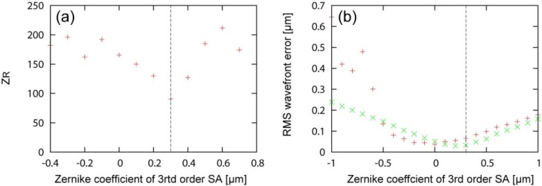
The Rayleigh length for each SA is shown in Fig. 9(a) . The Rayleigh length was the shortest when +0.3-µm SA was applied. was approximately 2 times longer with –0.4-µm SA ( = 182 µm) than with +0.3-µm SA ( = 90.5 µm). The minimum lateral resolutions were reduced in 1.2 times with –0.4-µm SA ( = 4.9 µm) than with +0.3-µm SA ( = 4.2 µm).
Fig. 9.
ZR for each SA are shown in (a). RMS wavefront errors for each SA are shown in (b). The + and × indicate the experimental and the simulation results, respectively.
On the other hands, the numerical simulation results obtained by Zemax showed that the DOF, which is defined by the FWHM of central peak intensity profile along the depth, was extended 3.5 times with ± 0.7-µm SAs. Specifically, the estimated DOFs were 148 µm, 42.7 µm and 146 µm for SA = –0.7, 0.0, and +0.7 µm. The lateral resolution, which is defined by beam width, was degraded 1.5 times with ± 0.7-µm SAs (6.4 µm for both SAs) from that without SA (4.2 µm).
Figure 9 shows the RMS wavefront error during the phantom measurement as a function of SA. Here the RMS error is defined as the RMS error between the measured wavefront and the target wavefront which includes the controlled SA, the counter defocus and LCA cancelation. It was found that the RMS error increases as SA increases as same as Subsection 3.2. This is because of an inevitable property of our AO-control algorithm (see Appendix A). Note that the RMS errors with SA varying from –0.5 µm to –1.0 µm are unreliable.
7. Retinal imaging
According to the results of preceding sections, proper parameters for in vivo eye imaging can be selected. In this section, we demonstrate high-resolution human retinal imaging with extended DOF. We investigated the effect of SA by imaging several eyes and the numerical simulation.
7.1. Method
7.1.1. Human retinal imaging for three healthy eyes
Three eyes of 3 normal subjects were involved in this study. The demographics of the subjects are summarized in Table 2 . The imaging region was set to 5 degree superior to the fovea. The imaged region on the retina was controlled by a fixation target placed on an optical conjugate of the retina. For the stability of fixation, the dominant eye of each subject was measured. Before the measurement, two drops of 0.5% tropicamide and 0.5% phenylephrine hydrochloride were applied for pupil dilation.
Table 2. Subjects’ characteristics. Sph and Cyl: spherical and cylindrical powers in diopters.
| Subject ID | Refractive error | Sph (D) | Cyl (D) | Eye (L/R) | Age |
|---|---|---|---|---|---|
| 1 | Myopia | –7.3 | –0.3 | R | 25 |
| 2 | Emmetropia | –1.7 | –0.1 | R | 31 |
| 3 | Myopia | –6.6 | –0.4 | R | 24 |
In our case, the maximum applicable SA was ± 0.4 µm. In other words, AO-closed loop cannot converge with a target aberration larger than this maximum. Because there is the inevitable residual wavefront error discussed in Section 4 and Fig. 3. In this study, we applied SA of ± 0.4 µm and its associated counter defocus. Optical power on the cornea was 1.28 mW for a probing beam and 96 µW for an AO beacon. These optical powers respect the safety limit defined by the American National Standard Institute [52]. Volumetric measurements were performed at dimensions of 0.8 degree × 0.8 degree (128 × 128) A-lines. Nine sequential volumes were acquired at a speed of 5.6 volumes/s in a single measurement session.
For the image comparison, we generated en face averaged projection images of the photoreceptor layer (PRL) with a projection thickness of 52 µm (21 pixels). The representative volumes which appeared with less involuntary eye motion artifacts are selected from the volumes taken at several measurement sessions. Because the most severe reason for blurring image was the involuntary eye motion artifacts, the manual selection process was necessary. For the quantitative assessment of the image quality, we calculated the RMS value of en face projection image of PRL. The reason why we selected this value is because of the higher correlation with the manual assessment than the others: sharpness metric, information entropy and Haralick features.
7.1.2. Intra-subject variability
In order to assess the intra-subject variability of the method, we examined an eye of subject-1 sequentially by altering the SA in order of –0.4-µm SA, 0.0-µm SA and +0.4-µm SA. In total, ten measurement sessions (30 volumes) were obtained for each SA. Then, the RMS values of the en face projection images of PRL, which were the mean signal intensity of the image, were obtained.
7.1.3. Numerical simulation for human retinal imaging
We numerically simulated the PSFs for human retinal imaging by using Zemax. The method is similar to Section 5. We used the human eye model by Liou and Brennan [53]. Then, the theoretical DOF and the lateral resolution were estimated.
7.2. Results
7.2.1. Human retinal imaging for three healthy eyes
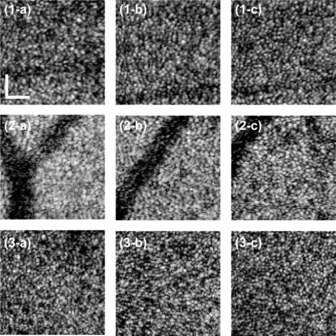
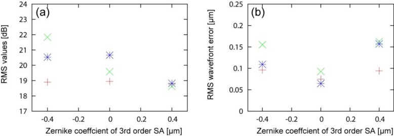
Figure 10 shows en face projection images of the photoreceptor layer (PRL). We qualitatively observed better image quality with –0.4-µm SA for all subjects than 0-µm or +0.4-µm SA. To more quantify the image, RMS of the image, i.e. the mean signal energy of the image was obtained. Comparable or higher RMS values were found with –0.4-µm SA than without SA as shown in Fig. 11(a) . The image quality with +0.4-µm SA was worse than the others.
Fig. 10.
En face projection images on PRL of subject-1 are shown in (1-a) with +0.4 µm SA, (1-b) without SA and (1-c) with –0.4-µm SA. Those of Subject-2 are shown in (2-a) with +0.4-µm SA, (2-b) without SA and (2-c) with –0.4-µm SA. Those of Subject-3 are shown in (3-a) with +0.4-µm SA, (3-b) without SA and (3-c) with –0.4-µm SA. Field of view of cropped images was 0.64 degree × 0.64 degree (102 pixels × 102 pixels). The white bar indicates 50 µm on the retina.
Fig. 11.
RMS values of en face projection images for SA = +0.4, 0.0 and –0.4 µm are shown in (a). Residual RMS wavefront errors for = +0.4, 0.0 and –0.4 µm are shown in (b). The +, ×, and * indicate subject-1, −2, and-3, respectively.
The residual RMS wavefront errors for each SA are shown in Fig. 11(b). Without SA, RMS wavefront errors were less than 0.1 µm for all subjects. Introduction of SA increases the RMS error up to around 0.16 µm (results ranged from 0.1 µm to 0.16 µm). Despite this increasing RMS error, we also found that the image quality for all subjects was better or comparable with –0.4-µm SA than without SA.
In order to see the more details, representative B-scan images of subject-1 for each SA are shown in Fig. 12 . The nerve fiber layer (NFL) was more brightly appeared with –0.4-µm SA than other SAs. However, the evident improved signal strength of NFL at –0.4-µm such as the case of Fig. 12 was found not for all cases, and there were large fluctuations of the OCT signal intensity. It was difficult to discriminate between the effects of SA from the other factors. More details analysis of the effect of SA apart from other factors based on larger population would be a future study. The details are discussed in Subsection 8.2.
Fig. 12.

Representative B-scan images for SA = +0.4, 0.0 and –0.4 µm. The color bar indicates the SNR range in which the averaged intensity at the vitreous is set to be 0 dB. The black bar indicates 100 µm.
7.2.2. Intra-subject variability
To assess the inter-session variability of the method, 30 volumes are obtained with each of –0.4-µm, 0-µm, and +0.4-µm SAs. The RMS values of en face projection images were obtained as a measure of image quality. Nine volumes were excluded from the analysis because of evident eye motion. The mean values of RMS were 16.7, 16.4, and 16.2 for –0.4-µm SA, 0.0-µm SA and +0.4-µm SA, respectively. The median values of RMS were 16.9, 16.4 and 16.2 for –0.4-µm SA, 0.0-µm SA and +0.4-µm SA, respectively. The largest mean and median values were found with –0.4-µm SA. This indicates the better image quality with –0.4-µm SA than the others.
The interquartile ranges (IQRs) of the RMS values are 1.5, 1.9, and 1.7 for –0.4-µm SA, 0.0-µm SA and +0.4-µm SA, respectively. The largest IQR was found with 0.0-µm SA. Since larger IQR value indicates higher variability of the image quality and lower stability of the imaging, –0.4-µm SA shows the highest stability and 0.0-µm SA shows the lowest stability.
7.2.3. Numerical simulation for human retinal imaging
The numerical simulation results obtained by Zemax showed that the DOF was extended 3 times with ± 0.4-µm SA. Specifically, the estimated DOFs were 156 µm, 52.7 µm, and 157 µm for SA = –0.7, 0.0, and +0.7 µm. The lateral resolution was degraded in 1.4 times with ± 0.4-µm SA. Specifically, 5.8 µm, 4.3 µm, and 6.4 µm for SA = –0.7, 0.0, and +0.7 µm. If we achieved 3 times longer DOF by shrinking the beam diameter on the cornea, the lateral resolution is degraded in 1.7 times. Namely, 1.2 times better resolution is obtained with 0.4-µm SA than by simply reducing the beam diameter with the identical DOF.
8. Discussion
8.1. Sample induced spherical aberrations
In Section 5, the tightest focus was found with SA = +0.3 µm not with SA = 0.0 µm. The sample induced aberrations could explain this issue. Specifically, the refractive index mismatch between the air and the irregular gel surface induces depth dependent spherical aberrations [54,55]. We infer that the sample induced SA was canceled by the above mentioned SA of +0.3 µm. This assumption is derived from the following reasons. First, the system induced spherical aberrations is significantly small as mentioned in Section 4. Second, the most probable source of such amount of aberration is the irregular shape of gel surface. Because if we assumed the 3-mm thickness of a homogenous sample and the gel surface was flat, the expected sample induced spherical aberrations is approximately –0.03 µm, which is much smaller than the counter +0.3-µm SA.
8.2. Extension of DOF
According to the B-scan images of a phantom shown in Fig. 7, negative SA (less than +0.3-µm SA) elongates the focal range and shifts it farther away from the lens. This property is consistent with the theoretical prediction. However, in the case of positive SA (more than +0.3-µm SA), no evident directionality was found in the phantom imaging. This is because of the increase of RMS wavefront error as shown in Fig. 9(b). According to Fig. 9(b), the RMS wavefront errors were kept relatively low when negative SA was applied, while they monotonically increased when positive SA was applied. Therefore, the phantom imaging also indicates the extension of DOF and their directionality as confirmed in Section 5. In addition, the averaged intensity profiles were useful to find the OCT signal intensity enhancement with SA, and it was round 1–2 dB.
For the retinal imaging, the slight differences of image contrast were observed among several SA values as mentioned in Subsections 7.2.1 and 7.2.2. Through the measurement, we qualitatively and quantitatively observed the equivalent or higher contrast of cone mosaic with –0.4-µm SA than without SA. However, there were no statistically significant differences. The reasons would be explained by the larger fluctuation of the OCT signal intensity than the effect of SA. For instance, the OCT signal intensity gain with SA was found only 1–2 dB in the phantom imaging. However, for the human retinal imaging, there are large fluctuations from the other factors: involuntary motion artifacts, structural changes, and OCT signal decay.
8.3. Other benefits for retinal imaging
For the retinal imaging, the involuntary eye motion artifacts were the most severe problem. Secondly, proper alignment of the depth position of the focus is essential for high contrast imaging. There are several uncontrollable factors in this alignment. For instance, multi-layer structures in the retina cause a relatively large depth scattered field of a wavefront sensor images, hence the exact depth position of wavefront sensing is not predictable. In addition, micro-fluctuations of the accommodation also result in fluctuations in the depth position of the reference of the wavefront measurement [16,30]. Involuntary eye motion could also be a cause of turbulence. In AO retinal imaging, the depth position of the focus is aligned based on an en face image. This maneuver is easy and practical for AOSLO and a flood illumination AO fundus camera. However, it is not totally compatible with AOOCT because AOOCT, with the exception of T-scan time domain AOOCT, required a full volumetric acquisition to obtain an en face image. In this circumstance, a long focal range obtained by intentionally induced SA becomes beneficial. This benefit might be resulted in the high contrast photoreceptor imaging with –0.4-µm SA in Subsections 7.2.1 and 7.2.2, and it also results in smaller IQRs with SAs in Subsection 7.2.2.
9. Conclusion
In conclusion, an extended DOF system using SA was implemented to extend focal range while preserving lateral resolution. The extension of the focal range was theoretically, numerically, and experimentally confirmed. Finally, we demonstrated in vivo human retinal imaging by altering SAs.
Acknowledgments
This study was supported in part by the Japan Science and Technology Agency through a program of Development of Systems and Technology for Advanced Measurement and Analysis and by Japan Society for Promotion of Science (JSPS) under contract KAKENHI 11J01983. Kazuhiro Kurokawa was supported by JSPS through a program of Research Fellowship for Young Scientist.
Appendix A
The achievable smallest residual wavefront error increases by introducing a target slope. The residual wavefront error, or so-called target reconstruction error, increases roughly in proportion to the difference of the shapes of deformable mirror at the initial state and the state which perfectly generates the target wavefront. This theoretical limit on the target reconstruction error is discussed in this appendix. The theoretical limit is important because the practically applicable amount of SA of our method was limited by this factor.
Assume the AO closed loop is driven by an integral controller. The measured slope vector at the nth iteration of the closed loop se will be given by
| (A1) |
where t is time, n is the number of iterations of the AO closed loop, is a constant slope vector which represents the static total aberration of the system and the aberration of a sample when the deformable mirror is flattened, and is a reconstructed slope vector which is defined as
| (A2) |
where A is an influence matrix of the AO-setup, A+ is the Moore-Penrose pseudo inverse matrix of A, and α represents a closed-loop gain. is a target slope vector.
As described in Subsection 2.2.2, a command vector at the time of with the target slope vector is defined as
| (A3) |
From Eqs. (A1)-(A3), the expected slope vector can be rewritten as
| (A4) |
Here, the expected slope vector after subtraction of the target slope vector is defined as residual error
| (A5) |
In Eq. (A5), if n is sufficiently large and the sample is static, residual error can expressed as
| (A6) |
where the following relation was used
| (A7) |
Equation (A6) indicates that if AA+ is unity, the target reconstruction error is always zero. However, in practice, . Under this practical condition, residual aberration becomes larger as the change of the deformable mirror from its initial state is larger.
This means when we start the closed loop with a flattened deformable mirror, a larger target slope raises a larger minimally achievable residual error.
As shown in the model eye experiment (Section 4) and phantom experiment (Subsection 6.2), residual error increased with the amount of applied SA, i.e., the target slope. The numerical simulation results based on the parameters and influence matrices of the experiment are plotted in Fig. 3(b) and Fig. 9 (green plots). It was found the theory explained the experiment well except for the sample induced aberration.
Note that this discussion is based on an assumption that the sample has a constant aberration in time. If the sample has a dynamic aberration, this effect becomes more severe, which can be modeled by converting to in the Eq. (A1), although is not predictable.
References and links
- 1.Huang D., Swanson E. A., Lin C. P., Schuman J. S., Stinson W. G., Chang W., Hee M. R., Flotte T., Gregory K., Puliafito C. A., Fujimoto J. G., “Optical coherence tomography,” Science 254(5035), 1178–1181 (1991). 10.1126/science.1957169 [DOI] [PMC free article] [PubMed] [Google Scholar]
- 2.Fercher A. F., Hitzenberger C. K., Kamp G., El-Zaiat S. Y., “Measurement of intraocular distances by backscattering spectral interferometry,” Opt. Commun. 117(1-2), 43–48 (1995). 10.1016/0030-4018(95)00119-S [DOI] [Google Scholar]
- 3.Costa R. A., Skaf M., Melo L. A. S., Jr, Calucci D., Cardillo J. A., Castro J. C., Huang D., Wojtkowski M., “Retinal assessment using optical coherence tomography,” Prog. Retin. Eye Res. 25(3), 325–353 (2006). 10.1016/j.preteyeres.2006.03.001 [DOI] [PubMed] [Google Scholar]
- 4.Alam S., Zawadzki R. J., Choi S., Gerth C., Park S. S., Morse L., Werner J. S., “Clinical application of rapid serial fourier-domain optical coherence tomography for macular imaging,” Ophthalmology 113(8), 1425–1431 (2006). 10.1016/j.ophtha.2006.03.020 [DOI] [PMC free article] [PubMed] [Google Scholar]
- 5.Chen T. C., Zeng A., Sun W., Mujat M., de Boer J. F., “Spectral domain optical coherence tomography and glaucoma,” Int. Ophthalmol. Clin. 48(4), 29–45 (2008). 10.1097/IIO.0b013e318187e801 [DOI] [PMC free article] [PubMed] [Google Scholar]
- 6.Sakata L. M., Deleon-Ortega J., Sakata V., Girkin C. A., “Optical coherence tomography of the retina and optic nerve - a review,” Clin. Experiment. Ophthalmol. 37(1), 90–99 (2009). 10.1111/j.1442-9071.2009.02015.x [DOI] [PubMed] [Google Scholar]
- 7.Häusler G., “’Coherence radar’ and ‘spectral radar’—new tools for dermatological diagnosis,” J. Biomed. Opt. 3(1), 21 (1998). 10.1117/1.429899 [DOI] [PubMed] [Google Scholar]
- 8.de Boer J. F., Cense B., Park B. H., Pierce M. C., Tearney G. J., Bouma B. E., “Improved signal-to-noise ratio in spectral-domain compared with time-domain optical coherence tomography,” Opt. Lett. 28(21), 2067–2069 (2003). 10.1364/OL.28.002067 [DOI] [PubMed] [Google Scholar]
- 9.Leitgeb R., Hitzenberger C. K., Fercher A. F., “Performance of fourier domain vs. time domain optical coherence tomography,” Opt. Express 11(8), 889–894 (2003). 10.1364/OE.11.000889 [DOI] [PubMed] [Google Scholar]
- 10.Nassif N., Cense B., Park B., Pierce M., Yun S., Bouma B., Tearney G., Chen T., de Boer J., “In vivo high-resolution video-rate spectral-domain optical coherence tomography of the human retina and optic nerve,” Opt. Express 12(3), 367–376 (2004). 10.1364/OPEX.12.000367 [DOI] [PubMed] [Google Scholar]
- 11.Liang J., Williams D. R., “Aberrations and retinal image quality of the normal human eye,” J. Opt. Soc. Am. A 14(11), 2873–2883 (1997). 10.1364/JOSAA.14.002873 [DOI] [PubMed] [Google Scholar]
- 12.Donnelly W. J., 3rd, Roorda A., “Optimal pupil size in the human eye for axial resolution,” J. Opt. Soc. Am. A 20(11), 2010–2015 (2003). 10.1364/JOSAA.20.002010 [DOI] [PubMed] [Google Scholar]
- 13.Liang J., Williams D. R., Miller D. T., “Supernormal vision and high-resolution retinal imaging through adaptive optics,” J. Opt. Soc. Am. A 14(11), 2884–2892 (1997). 10.1364/JOSAA.14.002884 [DOI] [PubMed] [Google Scholar]
- 14.Fernández E. J., Iglesias I., Artal P., “Closed-loop adaptive optics in the human eye,” Opt. Lett. 26(10), 746–748 (2001). 10.1364/OL.26.000746 [DOI] [PubMed] [Google Scholar]
- 15.Hofer H., Chen L., Yoon G.-Y., Singer B., Yamauchi Y., Williams D. R., “Improvement in retinal image quality with dynamic correction of the eye’s aberrations,” Opt. Express 8(11), 631–643 (2001). 10.1364/OE.8.000631 [DOI] [PubMed] [Google Scholar]
- 16.Hofer H., Artal P., Singer B., Aragón J. L., Williams D. R., “Dynamics of the eye’s wave aberration,” J. Opt. Soc. Am. A 18(3), 497–506 (2001). 10.1364/JOSAA.18.000497 [DOI] [PubMed] [Google Scholar]
- 17.Rha J., Jonnal R. S., Thorn K. E., Qu J., Zhang Y., Miller D. T., “Adaptive optics flood-illumination camera for high speed retinal imaging,” Opt. Express 14(10), 4552–4569 (2006). 10.1364/OE.14.004552 [DOI] [PubMed] [Google Scholar]
- 18.Larichev A. V., Ivanov P. V., Iroshnikov N. G., Shmalgauzen V. I., Otten L. J., “Adaptive system for eye-fundus imaging,” Quantum Electron. 32(10), 902–908 (2002). 10.1070/QE2002v032n10ABEH002314 [DOI] [Google Scholar]
- 19.Roorda A., Romero-Borja F., Donnelly Iii W., Queener H., Hebert T., Campbell M., “Adaptive optics scanning laser ophthalmoscopy,” Opt. Express 10(9), 405–412 (2002). [DOI] [PubMed] [Google Scholar]
- 20.Burns S. A., Tumbar R., Elsner A. E., Ferguson D., Hammer D. X., “Large-field-of-view, modular, stabilized, adaptive-optics-based scanning laser ophthalmoscope,” J. Opt. Soc. Am. A 24(5), 1313–1326 (2007). 10.1364/JOSAA.24.001313 [DOI] [PMC free article] [PubMed] [Google Scholar]
- 21.Ferguson R. D., Zhong Z., Hammer D. X., Mujat M., Patel A. H., Deng C., Zou W., Burns S. A., “Adaptive optics scanning laser ophthalmoscope with integrated wide-field retinal imaging and tracking,” J. Opt. Soc. Am. A 27(11), A265–A277 (2010). 10.1364/JOSAA.27.00A265 [DOI] [PMC free article] [PubMed] [Google Scholar]
- 22.Hermann B., Fernández E. J., Unterhuber A., Sattmann H., Fercher A. F., Drexler W., Prieto P. M., Artal P., “Adaptive-optics ultrahigh-resolution optical coherence tomography,” Opt. Lett. 29(18), 2142–2144 (2004). 10.1364/OL.29.002142 [DOI] [PubMed] [Google Scholar]
- 23.Zhang Y., Rha J., Jonnal R., Miller D., “Adaptive optics parallel spectral domain optical coherence tomography for imaging the living retina,” Opt. Express 13(12), 4792–4811 (2005). 10.1364/OPEX.13.004792 [DOI] [PubMed] [Google Scholar]
- 24.Zawadzki R. J., Jones S. M., Olivier S. S., Zhao M., Bower B. A., Izatt J. A., Choi S., Laut S., Werner J. S., “Adaptive-optics optical coherence tomography for high-resolution and high-speed 3D retinal in vivo imaging,” Opt. Express 13(21), 8532–8546 (2005). 10.1364/OPEX.13.008532 [DOI] [PMC free article] [PubMed] [Google Scholar]
- 25.Zawadzki R. J., Cense B., Zhang Y., Choi S. S., Miller D. T., Werner J. S., “Ultrahigh-resolution optical coherence tomography with monochromatic and chromatic aberration correction,” Opt. Express 16(11), 8126–8143 (2008). 10.1364/OE.16.008126 [DOI] [PMC free article] [PubMed] [Google Scholar]
- 26.Cense B., Gao W., Brown J. M., Jones S. M., Jonnal R. S., Mujat M., Park B. H., de Boer J. F., Miller D. T., “Retinal imaging with polarization-sensitive optical coherence tomography and adaptive optics,” Opt. Express 17(24), 21634–21651 (2009). 10.1364/OE.17.021634 [DOI] [PMC free article] [PubMed] [Google Scholar]
- 27.Kurokawa K., Sasaki K., Makita S., Yamanari M., Cense B., Yasuno Y., “Simultaneous high-resolution retinal imaging and high-penetration choroidal imaging by one-micrometer adaptive optics optical coherence tomography,” Opt. Express 18(8), 8515–8527 (2010). 10.1364/OE.18.008515 [DOI] [PubMed] [Google Scholar]
- 28.Zacharria M., Lamory B., Chateau N., “Biomedical imaging: New view of the eye,” Nat. Photonics 5(1), 24–26 (2011). 10.1038/nphoton.2010.298 [DOI] [Google Scholar]
- 29.Godara P., Dubis A. M., Roorda A., Duncan J. L., Carroll J., “Adaptive optics retinal imaging: emerging clinical applications,” Optom. Vis. Sci. 87(12), 930–941 (2010). 10.1097/OPX.0b013e3181ff9a8b [DOI] [PMC free article] [PubMed] [Google Scholar]
- 30.Leahy C., Leroux C., Dainty C., Diaz-Santana L., “Temporal dynamics and statistical characteristics of the microfluctuations of accommodation: dependence on the mean accommodative effort,” Opt. Express 18(3), 2668–2681 (2010). 10.1364/OE.18.002668 [DOI] [PubMed] [Google Scholar]
- 31.Zalevsky Z., “Extended depth of focus imaging: a review,” SPIE Rev. 1(1), 018001 (2010). 10.1117/6.0000001 [DOI] [Google Scholar]
- 32.Richdale K., Mitchell G. L., Zadnik K., “Comparison of multifocal and monovision soft contact lens corrections in patients with low-astigmatic presbyopia,” Optom. Vis. Sci. 83(5), 266–273 (2006). 10.1097/01.opx.0000216098.62165.34 [DOI] [PubMed] [Google Scholar]
- 33.Javitt J. C., Steinert R. F., “Cataract extraction with multifocal intraocular lens implantation: a multinational clinical trial evaluating clinical, functional, and quality-of-life outcomes,” Ophthalmology 107(11), 2040–2048 (2000). 10.1016/S0161-6420(00)00368-7 [DOI] [PubMed] [Google Scholar]
- 34.Kim M. J., Zheleznyak L., Macrae S., Tchah H., Yoon G., “Objective evaluation of through-focus optical performance of presbyopia-correcting intraocular lenses using an optical bench system,” J. Cataract Refract. Surg. 37(7), 1305–1312 (2011). 10.1016/j.jcrs.2011.03.033 [DOI] [PMC free article] [PubMed] [Google Scholar]
- 35.Dowski E. R., Jr, Cathey W. T., “Extended depth of field through wave-front coding,” Appl. Opt. 34(11), 1859–1866 (1995). 10.1364/AO.34.001859 [DOI] [PubMed] [Google Scholar]
- 36.Dufour P., Piché M., De Koninck Y., McCarthy N., “Two-photon excitation fluorescence microscopy with a high depth of field using an axicon,” Appl. Opt. 45(36), 9246–9252 (2006). 10.1364/AO.45.009246 [DOI] [PubMed] [Google Scholar]
- 37.Botcherby E. J., Juškaitis R., Wilson T., “Scanning two photon fluorescence microscopy with extended depth of field,” Opt. Commun. 268(2), 253–260 (2006). 10.1016/j.optcom.2006.07.026 [DOI] [Google Scholar]
- 38.Pircher M., Götzinger E., Hitzenberger C. K., “Dynamic focus in optical coherence tomography for retinal imaging,” J. Biomed. Opt. 11(5), 054013 (2006). 10.1117/1.2358960 [DOI] [PubMed] [Google Scholar]
- 39.Ding Z., Ren H., Zhao Y., Nelson J. S., Chen Z., “High-resolution optical coherence tomography over a large depth range with an axicon lens,” Opt. Lett. 27(4), 243–245 (2002). 10.1364/OL.27.000243 [DOI] [PubMed] [Google Scholar]
- 40.Leitgeb R. A., Villiger M., Bachmann A. H., Steinmann L., Lasser T., “Extended focus depth for Fourier domain optical coherence microscopy,” Opt. Lett. 31(16), 2450–2452 (2006). 10.1364/OL.31.002450 [DOI] [PubMed] [Google Scholar]
- 41.Burvall A., Kołacz K., Jaroszewicz Z., Friberg A. T., “Simple lens axicon,” Appl. Opt. 43(25), 4838–4844 (2004). 10.1364/AO.43.004838 [DOI] [PubMed] [Google Scholar]
- 42.Yoshida A., “Spherical aberration in beam optical systems,” Appl. Opt. 21(10), 1812–1816 (1982). 10.1364/AO.21.001812 [DOI] [PubMed] [Google Scholar]
- 43.Rivolta C., “Depth of focus of optical systems with a small amount of spherical aberration,” Appl. Opt. 29(22), 3249–3254 (1990). 10.1364/AO.29.003249 [DOI] [PubMed] [Google Scholar]
- 44.Alkelly A. A., “Spot size and radial intensity distribution of focused Gaussian beams in spherical and non-spherical aberration lenses,” Opt. Commun. 277(2), 397–405 (2007). 10.1016/j.optcom.2007.05.031 [DOI] [Google Scholar]
- 45.Kurokawa K., Tamada D., Makita S., Yasuno Y., “Adaptive optics retinal scanner for one-micrometer light source,” Opt. Express 18(2), 1406–1418 (2010). 10.1364/OE.18.001406 [DOI] [PubMed] [Google Scholar]
- 46.Fernández E. J., Unterhuber A., Povazay B., Hermann B., Artal P., Drexler W., “Chromatic aberration correction of the human eye for retinal imaging in the near infrared,” Opt. Express 14(13), 6213–6225 (2006). 10.1364/OE.14.006213 [DOI] [PubMed] [Google Scholar]
- 47.L. Chen, “Control algorithms,” in Adaptive Optics for Vision Science: Principles, Practices, Design and Applications, J. Porter, H. Queener, J. Lin, K. Thorn, and A. A. S. Awwal, eds. (Wiley-Interscience, 2006). [Google Scholar]
- 48.J. E. Greivenkamp, “Spherical aberration and defocus,” in Field Guide to Geometrical Optics (SPIE, 2003), pp. 119–130. [Google Scholar]
- 49.G. Dai, “Ocular wavefront conversion,” in Wavefront Optics for Vision Correction, illustrated ed. (SPIE, 2008), pp. 132–137. [Google Scholar]
- 50.E. Hecht, “Modern optics: lasers and other topics,” in Optics, 4th ed. (Addison Wesley, 2001). [Google Scholar]
- 51.Ralston T. S., Marks D. L., Carney P. S., Boppart S. A., “Interferometric synthetic aperture microscopy,” Nat. Phys. 3(2), 129–134 (2007). 10.1038/nphys514 [DOI] [PMC free article] [PubMed] [Google Scholar]
- 52.American National Standards Institute, “American National Standard for the Safe Use of Lasers,” ANSI Z136.1-2000 (ANSI, New York, 2000).
- 53.Liou H.-L., Brennan N. A., “Anatomically accurate, finite model eye for optical modeling,” J. Opt. Soc. Am. A 14(8), 1684–1695 (1997). 10.1364/JOSAA.14.001684 [DOI] [PubMed] [Google Scholar]
- 54.Sheppard C. J. R., Gu M., “Aberration compensation in confocal microscopy,” Appl. Opt. 30(25), 3563–3568 (1991). 10.1364/AO.30.003563 [DOI] [PubMed] [Google Scholar]
- 55.Hell S., Reiner G., Cremer C., Stelzer E. H. K., “Aberrations in confocal fluorescence microscopy induced by mismatches in refractive index,” J. Microsc. 169(3), 391–405 (1993). 10.1111/j.1365-2818.1993.tb03315.x [DOI] [Google Scholar]


