Abstract
Digital holographic microscopy (DHM) has been applied extensively to in vitro studies of different living cells. In this paper, we present a novel application of an off-axis DHM system to in vivo study of the development of zebrafish embryos. Even with low magnification microscope objectives, the morphological structures and individual cell types inside developing zebrafish embryos can be clearly observed from reconstructed amplitude images. We further study the dynamic process of blood flow in zebrafish embryos. A calibration routine and post-processing procedures are developed to quantify physiological parameters at different developmental stages. We measure quantitatively the blood flow as well as the heart rate to study the effects of elevated D-glucose (abnormal condition) on circulatory and cardiovascular systems of zebrafish embryos. To enhance our ability to use DHM as a quantitative tool for potential high throughput screening application, the calibration and post-processing algorithms are incorporated into an automated processing software. Our results show that DHM is an excellent non-invasive imaging technique for visualizing the cellular dynamics of organogenesis of zebrafish embryos in vivo.
OCIS codes: (090.1995) Digital holography, (170.3880) Medical and biological imaging, (180.0180) Microscopy
1. Introduction
Since the last decade, zebrafish (Danio rerio) has become an important vertebrate model system for a wide range of basic and medical research [1–4]. Its popularity as a research model system can be attributed to a number of factors that include small size, rapid development, large clutch size, optical transparency and development outside of their mothers. These features of zebrafish highlight the advantages of zebrafish system over other vertebrate systems. Most importantly, gene functions and developmental pathways are well conserved between zebrafish and human, indicating that zebrafish can be used to model human diseases [5–10]. Due to the optical transparency and rapid development, zebrafish has also been widely used for in vivo imaging for examining the cellular dynamics of organogenesis under normal and abnormal conditions [11–14]. Different types of imaging techniques have been used and developed for high-resolution in vivo visualization of different biological processes of zebrafish, including the most commonly used laser scanning confocal, two-photon and spinning disk microscopy [11, 15–17]. The ability to directly observe the morphogenetic cell behaviors in vivo during embryogenesis, organogenesis and pathogenesis has greatly enhanced our ability to understand the molecular and genetic causes for varieties of human defects and diseases.
Recent reports have shown the potential application of DHM for life science research, offering high resolution and real-time observation capabilities without the need for fluorescence labeling of samples as required by the commonly used fluorescence microscopy [18, 19]. In DHM, a microscope objective (MO) is introduced in the path of the object wave to obtain a magnification. Since the complex amplitude of the optical field can be analyzed numerically during holographic reconstruction, the phase information of the object wave, which relates to optical path length linearly when unwrapped, is accessible with phase aberration corrected [20–22]. Therefore, DHM has been applied to microstructure characterization in reflection imaging [23, 24] and topography measurement of live cells in transmission imaging [25–30]. DHM can provide diffraction-limited lateral resolution comparable to common optical microscopy, and is capable of measuring optical path or thickness with sub-wavelength accuracy [25,31]. In addition, the temporal resolution of the DHM system is simply determined by the frame rate of the digital camera used for hologram recording. Consequently, DHM is also well suited for quantitative observation of dynamic processes [30–32]. Since the object wave can be reconstructed at any desired plane from a single hologram, DHM also offers the feature of digital focusing, which enables auto-focusing at different target plane to facilitate the observation of the desired characteristics of the sample [33, 34]. Because DHM is commonly used to implement quantitative phase imaging [35], it is limited to in vitro imaging of individual cells and there are few applications of DHM on in vivo imaging of vertebrate animal systems. Recently, a low-coherence phase-shifting DHM system in reflection mode is developed to conduct the optical sectioning of the zebrafish in vivo [36]. A coherence gate is used to select the imaging depth and mechanical scanning is required to image different depths of the sample. Additionally, four phase-shifted holograms are needed to obtain one hologram. Consequently, this technique is not suitable for imaging dynamic processes.
In this paper, we report our investigation on the capability of a typical transmission DHM system to image the embryonic development and to analyze the blood flow of zebrafish embryos. Initially, we examine the capability of the system by capturing images of live zebrafish embryos at various stages of development under different magnifications. The reconstructed amplitude images are of good quality even when a simple low magnification MO is used. The capability of our DHM system is further tested for the quantification and characterization of specific physiological parameters of different organs of developing zebrafish embryos under normal and abnormal conditions. To do this, we generate zebrafish embryos with elevated D-glucose exposure as previously described [37]. The treatment of elevated D-glucose causes zebrafish embryos to exhibit cardiac defects that are similar to human hyperglycemia. It is shown that our DHM system is capable of detecting quantitative differences in the blood flow rate between the D-glucose treated and wild-type embryos. In addition, we determine a strong correlation between the elevated D-glucose and the elevated heart rate of treated embryos. More importantly, DHM, with additional automated features, can be used as an excellent alternative to the established fluorescence microscopy for life science research, in particular, for potential high throughput screening applications.
2. Materials and methods
2.1. DHM technique
Gabor [38] first introduced the concept of holography, where two steps are needed: recording and reconstruction. In the recording step, the interference pattern between the object wave and the reference wave is recorded on an imaging media. In the reconstruction step, the phase and amplitude information of the object wave are retrieved. The interference pattern on the hologram can be expressed as
| (1) |
when the hologram plane is within x − y plane. Er(x, y) and Eo(x, y) are the complex amplitudes of reference wave and object wave, respectively. In the reconstruction step, the original reference wave is used to illuminate the hologram and the object wave, which depicts the original object, emerges and propagates. This reconstructed object wave can be described mathematically by [39],
| (2) |
where d is the propagation distance from the hologram, ⊗ represents convolution operation, h(x, y, d) is the Rayleigh-Sommerfeld diffraction kernel
| (3) |
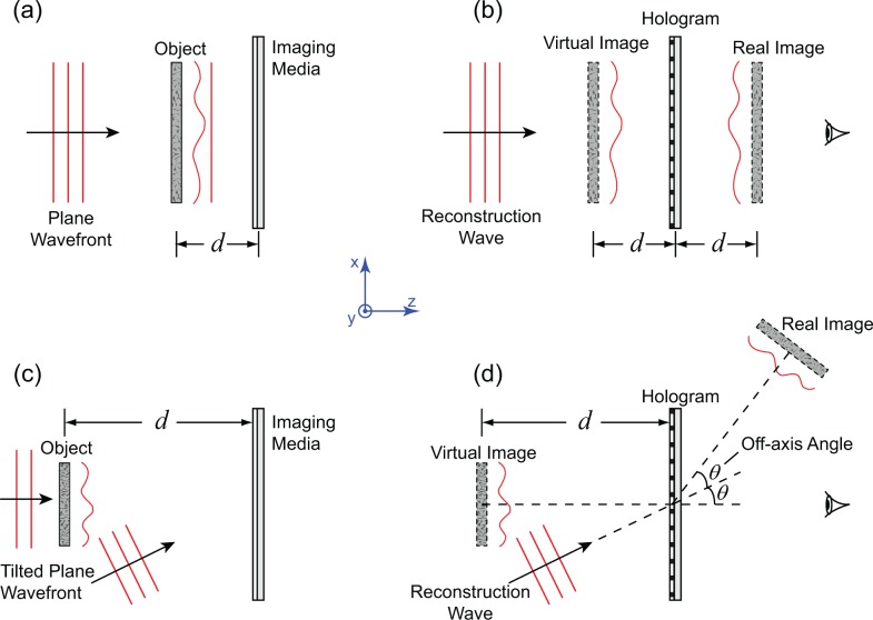
λ is the wavelength, and k is the wave number. The implementation of holography can be further categorized into in-line setup and off-axis setup, as shown in Fig. 1. In optical holography, the interference pattern is recorded by a holographic film that, after chemically processed, produces a hologram. The hologram is set up in middle of the reconstruction optics for obtaining the reconstructed images. Recent development of digital image recording technique enables an easy implementation of holography (termed digital holography), in which the hologram is recorded by sensors, e.g., CCD, and stored digitally, whereas the reconstruction can be fulfilled numerically. In particular, Eq. (2) can be evaluated numerically. Digital holography eliminates wet-processing of holograms in optical holography. Its numerical reconstruction process enables focusing different portions of the object digitally instead of mechanical focusing. However, in digital holography, the comparatively large pixel size of imaging sensors puts a stringent requirement on the angle between the reference wave and the object wave when the off-axis setup is used [40].
Fig. 1.
Schematic illustration of the principle of holography. (a) In-line recording. (b) In-line reconstruction. (c) Off-axis recording. (d) Off-axis reconstruction.
In DHM, a MO is introduced in the path of the object wave to obtain a magnified view of the object in the recording step. A digital camera records the hologram as a grayscale image. In the digital reconstruction step, by varying the depth d in the reconstruction routine, the complex amplitude of the object wave can be reconstructed at different planes, enabling DHM to focus at different depth planes digitally. Both the amplitude and phase information of the 3D optical field can be obtained from reconstructed complex amplitude. In addition, undesired terms recorded on the hologram can be filtered digitally before reconstruction.
2.2. Experimental setup
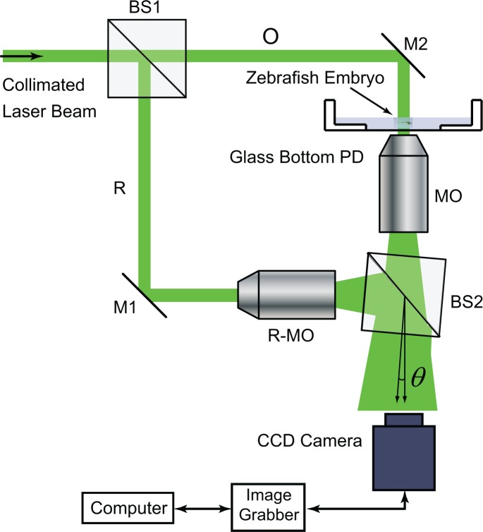
An off-axis transmission DHM system is developed, as shown in Fig. 2, to demonstrate the application of DHM for in vivo imaging of developing zebrafish embryos at various stages. In this DHM system, a collimated beam from a continuous-wave laser at 532 nm is split into the object beam and the reference beam. The object beam illuminates the zebrafish embryo sample whose magnified transmission image is then produced by the MO. By choosing different MOs, different magnifications of the imaging sample can be achieved. The plane reference beam is converted into the spherical wave by another MO, denoted as R-MO in Fig. 2, to match the wavefront of the object wave so that interference fringes can be easily resolved by the CCD camera. The MOs used in this study are 3.5X (Spencer, NA 0.09), 10X (Spencer, NA 0.25) and 40X (Olympus, UPLFLN40X, NA 0.75). The sensor size of the CCD camera (Imperx ICL-B4020) is 4008 × 2672 with 9 μm pixels, while another CCD camera (PCO2000, 7.4 μm pixels, 2048 × 2048) is used to image blood flow because of its higher frame rate (14 Hz). A translation stage adjusts the distance between the sample and the front lens of the MO by changing the vertical position of the sample.
Fig. 2.
Schematic illustration of the DHM system. BS, beam splitter; O, object beam; R, reference beam; M, mirror; PD, petri dish; R-MO, reference MO; θ, off-axis angle.
2.3. Numerical reconstruction
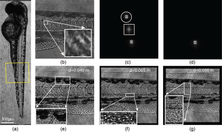
We adopt the angular spectrum method [41] to reconstruct the hologram numerically where the resolution of the reconstructed image is a constant, which is the physical size of one imaging pixel of the CCD camera. The reconstructed amplitude image is used to study the zebrafish embryos. The pre-processing of holograms includes zero-padding [42] and the filtering of the DC term and the twin image term by masking the Fourier spectrum of the hologram [43]. An example of hologram is shown in Fig. 3, together with its Fourier spectrum before and after masking, as well as reconstruction at different depths. Structures of the zebrafish embryo at different depth are observed, i.e., displaying a sharp image (in focus), by varying the values of d in Eq. (2).
Fig. 3.
Processing of zebrafish embryo holograms. (a) Reconstructed amplitude image of a 54 hour-post-fertilization (hpf) zebrafish embryo. The hologram is obtained using a 3.5X MO. Because of the limited field of view (FOV), two reconstructed image are combined to form the entire zebrafish embryo image. The square encloses the region of interest in subplots (b)–(g). (b) A hologram that records the trunk of the zebrafish, recorded using a 10X MO. Inset gives a zoom-in view of the recorded interference pattern. (c) The 2D Fourier spectrum of the hologram in (b). The twin image term (circled) and DC term (squared) are identified in a pre-processing step. (d) The Fourier spectrum with twin image term and DC term filtered digitally. (e) Reconstructed image at depth location d = 0.040 m. The spots on the body are in focus (inset). (f) Reconstruction at d = 0.065 m. The blood cells (white dots, inset) are in focus. (g) Reconstruction at d = 0.080 m. The gaps between somites and nodal cords are in focus (inset).
2.4. Calibration
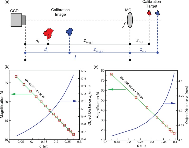
Zebrafish embryo is a three-dimensional object, thus reconstruction at different depth using DHM brings into focus of structures and tissues at different layers of the zebrafish (Figs. 3(e)–(g)). The physical dimensions of the images in Figs. 3(e)–(g) are all 1864Δ×1852Δ where Δ = 7.4 μm is the size of an individual CCD pixel. The obtained reconstruction images display different magnifications when d is different. This can be explained by the lens imaging model (Fig. 4(a)). In particular, the distance between the CCD sensor and the MO (l in Fig. 4(a) where the MO is simplified as a thin lens with focal length f) cannot be accurately measured or predetermined. Therefore, even when f is known, the magnification calculated using the thin lens equation is not accurate. In Fig. 4(a), zimg is the image distance and zo is the object distance.
Fig. 4.
Calibration method. (a) Schematic diagram of the calibration process. (b) A representative of calibration results for the 10X MO. (c) A representative of calibration results for the 40X MO.
To correct this, we design a calibration procedure so that the achieved magnification Mi at different depth location di can be determined without knowing l and f (subscript i denotes different target locations). From Fig. 4(a) and the thin lens equation, we have
| (4) |
from which a linear relationship can be found between Mi and di
| (5) |
In the calibration step, a USAF resolution target is set to a sequence of object distances zo,i by using the translation stage. The corresponding reconstruction depths di, at which the bars of the calibration target are in focus in the reconstructed images, are determined by maximizing the sharpness of the image. The corresponding magnification Mi is also measured by computing the size ratios of the images and targets. In this way, a sequence of di − Mi combinations can be obtained. The constants in Eq. (5), 1/f and l/f, are determined by curve fitting the experimental data. The calibration results (dependences of M and zo on d) are shown in Figs. 4(b) and (c), for two of the chosen MOs (10X and 40X. The 3.5X MO result is not shown). For example, for the 10X MO, the relationships are
| (6) |
and
| (7) |
In this way, the achieved magnification M can be calculated at each d using the calibration equation. The physical dimension of the experimental object can be evaluated by M and the size from the reconstructed image. The plots in Fig. 4 also justify the capacity of DHM for achieving a wide range of magnifications by using one MO.
2.5. Blood flow measurement
We develop an automated method to extract blood flow rate of the zebrafish embryo as an index to quantitatively characterize its cardiovascular function using the DHM system. This automated method is described below:
- Constant magnification in volume reconstruction is achieved to facilitate the forthcoming processing. If we consider a hologram recorded with a spherical reference wave that originates from (xr, yr, zr) (i.e., focal point of the R-MO), and the reconstruction is conducted at d2 and d1, the magnification ratio between the two reconstructed images is M2/M1. If a digital spherical wave originating from a shifted location (xr, yr, z′r) is used to reconstruct the hologram, the original reconstructed image at d2 appears at d′2 with a magnification M′ [41] where,
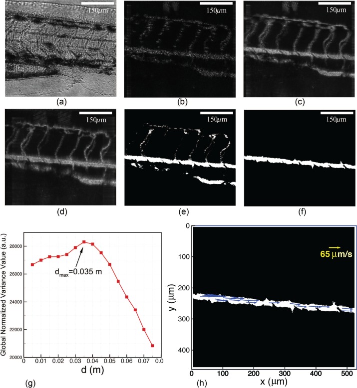
Accordingly, the varying size of the reconstructed image can be compensated to remain constant by introducing an appropriate z′r into reconstruction so that M′ = M1/M2 and thus the size of the reconstructed image at d′2 becomes the same as that of the reconstructed image at d1.(8) The geometries of the blood vessels are extracted from the reconstructed images by eliminating the background using sequential images. A video of the blood flow obtained from reconstructed images can be found in Fig. 5(a). Subtracting neighbor images in the sequence gives the difference image. The accumulation of such difference images fills the blood flow path leading to raw images of the blood vessel network. Raw images of blood vessels at different reconstruction depth d are thresholded separately. The multiplication of the resulting binary images gives a raw binary image of the blood vessels, from which the blood vessel (dorsal aorta) of interest is picked by morphological image processing. The diameter of the dorsal aorta can be extracted from this binary image of the blood vessel. The aforementioned procedures are illustrated in Figs. 5(b)–(f).
The focusing depth of blood cells is determined by maximizing the global normalized variance value through the reconstruction volume [44]. The searching is confined inside the blood vessel using the binary image of the blood vessel. A sample normalized variance profile is shown in Fig. 5(g). Then, the holograms are reconstructed at d = 0.035 m where the reconstruction gives focused image of blood cells.
The blood flow in the dorsal aorta is quantitatively evaluated by examining the motion of blood cells. Particle image velocimetry (PIV) [45] algorithm is applied to measure local flow velocity by treating blood cells as seeding particles that follow the blood flow. A resultant spatial distribution of velocity vectors is shown in Fig. 5(h). The averaged velocity V(t) is used to characterize the instantaneous blood flow. In addition, the volumetric flow rate in the blood vessel can be computed using Q(t) = V (t) · A, where A is the cross-section area of the blood vessel if we assume the blood vessel is of a circular shape.
Fig. 5.
Illustration of the auto-focusing and velocity extraction procedure. All images are recorded using the 10X MO. (a) Blood flow video made from reconstructed images ( Media 1 (2.2MB, MOV) ). (b) A difference image. (c) A raw image of the blood vessel reconstructed at d = 0.025 m. (d) A raw image of the blood vessel reconstructed at d = 0.06 m. (e) A raw binary image of the blood vessel. (f) The binary image of the blood vessel of interest. (g) A sample normalized variance profile. (h) Velocities of blood cell (shown as blue arrows) extracted by PIV algorithms.
This procedure is coded into an in-house developed software using LabVIEW. Thus it can be easily adopted into an automated processing routine for batch processing of large quantities of images.
2.6. Zebrafish embryo preparation
In the work done for this paper, adult zebrafish are raised and maintained at 28.5°C in system water. Embryos are obtained by natural spawning of adult wild-type AB strain fish. At the desired stages, embryos are collected and dechorionated for in vivo imaging. Before imaging, embryos are treated with tricaine to prevent from moving and then placed in the well of a glass-bottom petri dish (well depth 1.5 mm, glass thickness 0.1 mm) covered with a micro cover glass (thickness 0.14 mm) for imaging.
The D-glucose treatment is performed as described in [37]. Briefly, embryos are collected and allowed to develop to 6 hpf. We then separate zebrafish embryos at 6 hpf into three groups. One is used as normal control (wild-type) without any treatment. The other two groups are treated with 450 mg/dl D-glucose. The solution is renewed every 8 hrs. At the end of D-glucose treatment, embryos are prepared for imaging.
3. Results and discussion
3.1. Live imaging of developmental stages of zebrafish embryo by DHM
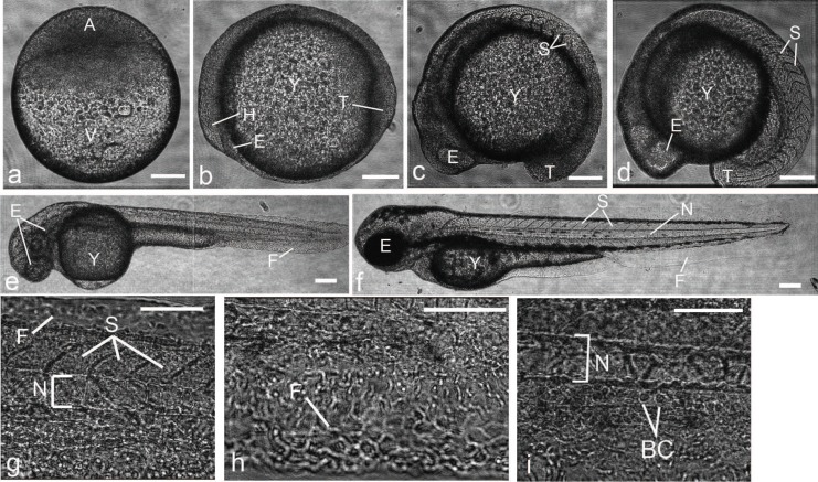
Using our DHM system, we collect holograms of zebrafish embryos at various stages of development with MOs of different magnifications (3.5X, 10X and 40X) and then process them as described earlier. The final reconstructed images of zebrafish embryos at various developmental stages are shown in Fig. 6. Using a 10X MO, we obtain different images of zebrafish embryos between 4 and 17 hpf. The early image of zebrafish embryo at 4 hpf is reconstructed at d = 0.03 m with calibrated magnification of 26.62, showing multipotent blastomeres developing over the yolk and without any defined morphological structures (Fig. 6(a)). The images of zebrafish embryos at 12 hpf (Fig. 6(b)) and 17 hpf (Fig. 6(c)) are reconstructed at d = 0.04 m with calibrated magnification of 26.00, showing structures of the eye at the head region, somites in the body and morphology of the tail region. At later stages of development, we use 3.5X MO to record whole images of zebrafish embryos. The image of the zebrafish embryo at 24 hpf is reconstructed at d = 0.06 m with calibrated magnification of 10.98. At 48 hpf, the image of the zebrafish is reconstructed at d = 0.04 m with calibrated magnification of 11.63. The lateral resolution of DHM is sufficiently high so that individual cells can be resolved even using the 3.5X MO. To examine the capability of DHM to visualize the developing tissue and cell morphologies of zebrafish embryo, the 40X MO is used to zoom into different regions of the developing zebrafish embryo (Figs. 6(g)–(i)). We reconstruct images from the mid-body section of zebrafish embryo at 48 hpf at d = 0.03 m with calibrated magnification of 97.05, showing structures of somites and notochord (Fig. 6(g)). The morphologies of individual cells within the tail fin (Fig. 6(h)) and individual blood cells in the dorsal aorta (Fig. 6(i)) are also observed from these reconstructed images. Our data show that DHM can be effectively used to record high resolution in vivo images with different magnifications using simple MOs.
Fig. 6.
Reconstructed amplitude images of developing whole zebrafish embryos and tissue structures. (a) Lateral view of an early zebrafish embryo at 4 hpf with animal pole to the top. (b)–(f) Side views with head (anterior) region to the left and back(dorsal) region to the top. Normal morphology of zebrafish embryos at 12 (b), 15 (c), 17 (d), 24 (e) and 48 (d) hpf. (g)–(i) Lateral views with anterior to the left. Higher magnification of the mid-body section of the developing zebrafish embryo at 48 hpf. A, animal pole; BC, blood cells; E, eye; F, fin; H, head; N, notochord; S, somites; T, tail; V, vegetal pole and Y, yolk. The scale bars are 150 μm in (a)–(f) and 75 μm in (g)–(i), respectively.
3.2. Quantitative analysis of the effects of elevated D-glucose on cardiovascular functions of zebrafish embryos by DHM
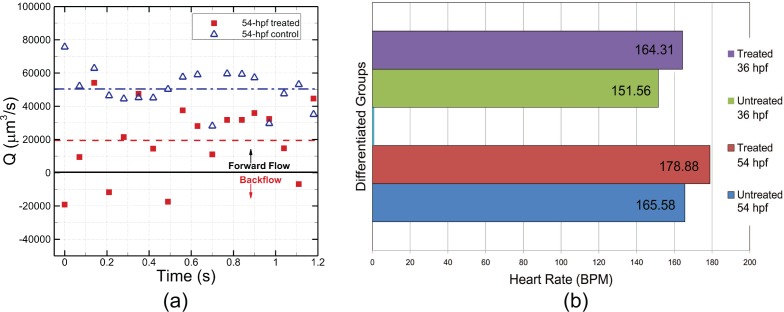
To demonstrate the imaging capability of DHM to detect and quantify different physiological parameters of developing zebrafish embryos under normal and abnormal conditions, we recreate zebrafish embryos with cardiovascular defects using D-glucose treatment as described in previous study in which they show that elevated D-glucose treatment can cause a range of cardiovascular defects in zebrafish embryos, from mild to severe that include abnormal cardiac looping [37]. A total of 20 zebrafish embryos are treated with 450 mg/dl of D-glucose at 6 hpf, and then allowed to develop in the presence of D-glucose until 54 hpf. A time sequence of blood flow holograms is taken from each of the D-glucose treated zebrafish and the time-resolved blood flow rate is determined by the processing approach as described in section 2.3.3. For comparison, we have taken a temporal sequence of holograms from same number of wild-type zebrafish embryos at 54 hpf to image the blood flow. One sample comparison is shown in Fig. 7(a). The heart beat period of a zebrafish is approximately 0.3 sec, thus the time range in the horizontal axis of Fig. 7(a) is about 4 times of the heart beat period. Significant variations of flow rate in accordance with the heart beat can be seen from the treated zebrafish. Negative velocities are also observed indicating the occurrence of backflow which is a strong evidence of cardiac defects of the treated zebrafish embryo. In contrast, blood flow rate of the untreated zebrafish shows much less time variances with a higher mean flow rate. The diverse cardiac malfunctions due to elevated D-glucose cause an adverse impact on the circulatory system of zebrafish embryos in terms of blood flow rate.
Fig. 7.
Effects of elevated D-glucose on cardiovascular function of zebrafish embryos. (a) Comparison of time-resolved blood flow rate between D-glucose treated and untreated wild-type zebrafish embryos. (b) Comparison of mean heart rate between D-glucose treated and untreated wild-type zebrafish embryo at 36 hpf and 54 hpf.
The heart rate is measured by analyzing the heart beat video obtained by reconstruction of sequential holograms taken of the heart region (data not shown). The heart rate of each zebrafish embryo in treated and control groups are measured. There are 20 zebrafish embryos in the treated 36-hpf group, 10 in the untreated 36-hpf group, 34 in the treated 54-hpf group and 16 in the untreated 54-hpf group. For both 36-hpf and 54-hpf groups, the mean heart rate of treated zebrafish embryos is slightly higher than that of untreated ones, as shown in Fig. 7(b). Due to the small difference of heart rate between treated and untreated groups as well as the variation of heart rate among individual zebrafish embryos, the paired t-test is applied to exam the significance of the heart rate difference. The difference is found to be significant, 0.01 < P < 0.025 for both 36-hpf and 54-hpf groups. Statistical analysis shows that it is highly possible that the higher heart rate is due to the treatment using elevated D-glucose.
4. Conclusion
Unlike fluorescence microscopy, DHM does not require imaging samples to be labeled with fluorescent probe. Although many established fluorescence imaging techniques offer high resolution capability, their effectiveness depends on photobleaching rates and signal-to-noise ratio. In addition, fluorescent molecules have a tendency to generate reactive chemical species under illumination of short wavelength light, resulting in greater susceptibility of live tissues and cells to phototoxicity. Because of these limitations, most conventional fluorescence microscopies suffer in their ability to observe fluorescent labeled live tissues or cells in vivo over long period of time.
DHM is an ideal technique for non-invasive in vivo imaging of biological structures and quantitative analysis of cellular dynamics of zebrafish embryos. Imaging sample does not need to be labeled with fluorescent probe, thus no concerns regarding to photobleaching rates and phototoxicity for the DHM system. We show that the DHM system can be used to obtain high quality images of zebrafish embryos at different developmental stages, which are comparable to those of common optical microscopy. From a single hologram, we are able to obtain transmission images at different depths of a zebrafish embryo by varying the reconstruction distance, bringing into focus of structures and tissues at different layers of zebrafish embryos, including eye, somites, notochord, vasculature and blood cells. Also, a calibration procedure is developed to enable us to use DHM as a quantitative tool for analyzing distinct physiological parameters of zebrafish during embryonic development. An automated algorithm is developed for tracking and measuring the movement of cells without the need for manual focusing as required by many traditional microscopies. We show that the automated algorithm software and DHM system can be used together to detect and quantify the blood flow and heart rates of developing zebrafish embryos under normal (wild-type) and abnormal (D-glucose treated) conditions. Using wild-type embryos as control, we detect the abnormal blood flow of D-glucose treated zebrafish embryos. A strong correlation is observed between the increased heart rate of treated zebrafish and exposure to elevated D-glucose. In summary, our data show that DHM can be used for measuring the biological functions and sizes of different tissues and structures of zebrafish embryos, without requiring fluorescent labeled sample. The further development of DHM will provide researchers a new imaging option to obtain high resolution images and capability of real-time observation. The volumetric and quantitative capabilities of DHM can be served as the basis for the future advancement of a high-throughput drug and mutation screening application for zebrafish, who is a very important model organism for studying developmental biology, toxicology, teratology, etc.
Different from confocal microscopy or optical coherence tomography, the DHM technique used in the present study can not reject out of focus light. Therefore, the in vivo appellation of transmission DHM is limited to organisms with good optical transparency, e.g., zebrafish embryos, C. elegans, etc. In addition, the automatic processing in high-throughput screening requires that zebrafish embryo maintains an identical pose in hologram recording step. A multi-well plate specifically developed for DHM diagnosis can ensure the right poses of zebrafish embryos. Finally, parallel computation by Graphics Processing Unit (GPU) is a promising resource to expedite the high-throughput analysis toward a real-time processing.
References and links
- 1.Stainier D. Y., Fishman M. C., “The zebrafish as a model system to study cardiovascular development,” Trends. Cardiovas. Med. 4, 207 – 212 (1994). 10.1016/1050-1738(94)90036-1 [DOI] [PubMed] [Google Scholar]
- 2.Lele Z., Krone P., “The zebrafish as a model system in developmental, toxicological and transgenic research,” Biotechnol. Adv. 14, 57 – 72 (1996). 10.1016/0734-9750(96)00004-3 [DOI] [PubMed] [Google Scholar]
- 3.Traver D., Hebomel P., Patton E., Murphey R. D., Yoder J. A., Litman G. W., Catic A., Amemiya C. T., Zon L. I., Trede N. S., “The zebrafish as a model organism to study development of the immune system,” Adv. Immunol. 81, 254 – 330 (2003). 10.1016/S0065-2776(03)81007-6 [DOI] [PubMed] [Google Scholar]
- 4.Glass A. S., Dahm R., “The zebrafish as a model organism for eye development.” Ophthalmic. Res. 36, 4–24 (2004). 10.1159/000076105 [DOI] [PubMed] [Google Scholar]
- 5.Dooley K., Zon L. I., “Zebrafish: a model system for the study of human disease,” Curr. Opin. Genet. Dev. 10, 252 – 256 (2000). 10.1016/S0959-437X(00)00074-5 [DOI] [PubMed] [Google Scholar]
- 6.Amatruda J. F., Shepard J. L., Stern H. M., Zon L. I., “Zebrafish as a cancer model system,” Cancer Cell 1, 229 – 231 (2002). 10.1016/S1535-6108(02)00052-1 [DOI] [PubMed] [Google Scholar]
- 7.Berman J., Hsu K., Look A. T., “Zebrafish as a model organism for blood diseases,” Brit. J. Haematol. 123, 568–576 (2003). 10.1046/j.1365-2141.2003.04682.x [DOI] [PubMed] [Google Scholar]
- 8.Lieschke G. J., Currie P. D., “Animal models of human disease: zebrafish swim into view,” Nat. Rev. Genet. 8, 353–367 (2007). 10.1038/nrg2091 [DOI] [PubMed] [Google Scholar]
- 9.Ali S., Champagne D. L., Spaink H. P., Richardson M. K., “Zebrafish embryos and larvae: A new generation of disease models and drug screens,” Birth Defects Res. C 93, 115–133 (2011). 10.1002/bdrc.20206 [DOI] [PubMed] [Google Scholar]
- 10.Jing L., Zon L. I., “Zebrafish as a model for normal and malignant hematopoiesis,” Dis. Model Mech. 4, 433–438 (2011). 10.1242/dmm.006791 [DOI] [PMC free article] [PubMed] [Google Scholar]
- 11.Cooper M. S., D’Amico L. A., Henry C. A., “Confocal microscopic analysis of morphogenetic movements,” Method Cell Biol. 59, 179–204 (1999). 10.1016/S0091-679X(08)61826-9 [DOI] [PubMed] [Google Scholar]
- 12.Jayachandran P., Hong E., Brewster R., “Labeling and imaging cells in the zebrafish hindbrain,” J. Vis. Exp. 41, e1976 (2010). [DOI] [PMC free article] [PubMed] [Google Scholar]
- 13.Kamei M., Isogai S., Pan W., Weinstein B. M., “Imaging blood vessels in the zebrafish,” Method Cell Biol. 100, 27 – 54 (2010). 10.1016/B978-0-12-384892-5.00002-5 [DOI] [PubMed] [Google Scholar]
- 14.Kettunen P., “Calcium imaging in the zebrafish,” Method Cell Biol. 740, 1039–1071 (2012). [DOI] [PubMed] [Google Scholar]
- 15.Combs C. A., Fluorescence Microscopy: A Concise Guide to Current Imaging Methods (John Wiley and Sons, Inc., 2010). [DOI] [PMC free article] [PubMed] [Google Scholar]
- 16.Yanik M. F., Rohde C. B., Pardo-Martin C., “Technologies for micromanipulating, imaging, and phenotyping small invertebrates and vertebrates,” Annu. Rev. Biomed. Eng. 13, 185–217 (2011). 10.1146/annurev-bioeng-071910-124703 [DOI] [PubMed] [Google Scholar]
- 17.Ball G., Parton R. M., Hamilton R. S., Davis I., “A cell biologist’s guide to high resolution imaging,” Method Enzymol. 504, 29 – 55 (2012). 10.1016/B978-0-12-391857-4.00002-1 [DOI] [PubMed] [Google Scholar]
- 18.Mann C., Yu L., Kim M., “Movies of cellular and sub-cellular motion by digital holographic microscopy,” Biomed. Eng. Online 5, 21 (2006). 10.1186/1475-925X-5-21 [DOI] [PMC free article] [PubMed] [Google Scholar]
- 19.Depeursinge C., Colomb T., Emery Y., Kuhn J., Charriere F., Rappaz B., Marquet P., “Digital holographic microscopy applied to life sciences,” Proc. IEEE Eng. Med. Biol. Soc. 2007, 6244–6247 (2007). [DOI] [PubMed] [Google Scholar]
- 20.Cuche E., Marquet P., Depeursinge C., “Simultaneous amplitude-contrast and quantitative phase-contrast microscopy by numerical reconstruction of Fresnel off-axis holograms,” Appl. Opt. 38, 6994–7001 (1999). 10.1364/AO.38.006994 [DOI] [PubMed] [Google Scholar]
- 21.Ferraro P., Nicola S. D., Finizio A., Coppola G., Grilli S., Magro C., Pierattini G., “Compensation of the inherent wave front curvature in digital holographic coherent microscopy for quantitative phase-contrast imaging,” Appl. Opt. 42, 1938–1946 (2003). 10.1364/AO.42.001938 [DOI] [PubMed] [Google Scholar]
- 22.Colomb T., Kühn J., Charrière F., Depeursinge C., Marquet P., Aspert N., “Total aberrations compensation in digital holographic microscopy with a reference conjugated hologram,” Opt. Express 14, 4300–4306 (2006). 10.1364/OE.14.004300 [DOI] [PubMed] [Google Scholar]
- 23.Xu L., Peng X., Miao J., Asundi A. K., “Studies of digital microscopic holography with applications to microstructure testing,” Appl. Opt. 40, 5046–5051 (2001). 10.1364/AO.40.005046 [DOI] [PubMed] [Google Scholar]
- 24.Coppola G., Ferraro P., Iodice M., Nicola S. D., Finizio A., Grilli S., “A digital holographic microscope for complete characterization of microelectromechanical systems,” Meas. Sci. Technol. 15, 529–539 (2004). 10.1088/0957-0233/15/3/005 [DOI] [Google Scholar]
- 25.Mann C., Yu L., Lo C.-M., Kim M., “High-resolution quantitative phase-contrast microscopy by digital holography,” Opt. Express 13, 8693–8698 (2005). 10.1364/OPEX.13.008693 [DOI] [PubMed] [Google Scholar]
- 26.Charrière F., Pavillon N., Colomb T., Depeursinge C., Heger T. J., Mitchell E. A. D., Marquet P., Rappaz B., “Living specimen tomography by digital holographic microscopy: morphometry of testate amoeba,” Opt. Express 14, 7005–7013 (2006). 10.1364/OE.14.007005 [DOI] [PubMed] [Google Scholar]
- 27.Kemper B., Carl D., Schnekenburger J., Bredebusch I., Schäfer M., Domschke W., von Bally G., “Investigation of living pancreas tumor cells by digital holographic microscopy,” J. Biomed. Opt. 11, 034005 (2006). 10.1117/1.2204609 [DOI] [PubMed] [Google Scholar]
- 28.Debailleul M., Simon B., Georges V., Haeberl O., Lauer V., “Holographic microscopy and diffractive microtomography of transparent samples,” Meas. Sci. Technol. 19, 074009 (2008). 10.1088/0957-0233/19/7/074009 [DOI] [Google Scholar]
- 29.Rappaz B., Barbul A., Hoffmann A., Boss D., Korenstein R., Depeursinge C., Magistretti P. J., Marquet P., “Spatial analysis of erythrocyte membrane fluctuations by digital holographic microscopy,” Blood Cell Mol. Dis. 42, 228 – 232 (2009). 10.1016/j.bcmd.2009.01.018 [DOI] [PubMed] [Google Scholar]
- 30.Yu L., Mohanty S., Zhang J., Genc S., Kim M. K., Berns M. W., Chen Z., “Digital holographic microscopy for quantitative cell dynamic evaluation during laser microsurgery,” Opt. Express 17, 12031–12038 (2009). 10.1364/OE.17.012031 [DOI] [PMC free article] [PubMed] [Google Scholar]
- 31.Rappaz B., Marquet P., Cuche E., Emery Y., Depeursinge C., Magistretti P., “Measurement of the integral refractive index and dynamic cell morphometry of living cells with digital holographic microscopy,” Opt. Express 13, 9361–9373 (2005). 10.1364/OPEX.13.009361 [DOI] [PubMed] [Google Scholar]
- 32.Antkowiak M., Torres-Mapa M. L., Dholakia K., Gunn-Moore F. J., “Quantitative phase study of the dynamic cellular response in femtosecond laser photoporation,” Biomed. Opt. Express 1, 414–424 (2010). 10.1364/BOE.1.000414 [DOI] [PMC free article] [PubMed] [Google Scholar]
- 33.Lee S. J., Seo K. W., Choi Y. S., Sohn M. H., “Three-dimensional motion measurements of free-swimming microorganisms using digital holographic microscopy,” Meas. Sci. Technol. 22, 064004 (2011). 10.1088/0957-0233/22/6/064004 [DOI] [Google Scholar]
- 34.Toy M. F., Richard S., Kühn J., Franco-Obregón A., Egli M., Depeursinge C., “Enhanced robustness digital holographic microscopy for demanding environment of space biology,” Biomed. Opt. Express 3, 313–326 (2012). 10.1364/BOE.3.000313 [DOI] [PMC free article] [PubMed] [Google Scholar]
- 35.Popescu G., Quantitative Phase Imaging of Cells and Tissues (McGraw-Hill, 2011). [Google Scholar]
- 36.Lin Y. C., Cheng C. J., Poon T. C., “Optical sectioning with a low-coherence phase-shifting digital holographic microscope,” Appl. Opt. 50, B25–B30 (2011). 10.1364/AO.50.000B25 [DOI] [PubMed] [Google Scholar]
- 37.Liang J., Gui Y., Wang W., Gao S., Li J., Song H., “Elevated glucose induces congenital heart defects by altering the expression of tbx5, tbx20, and has2 in developing zebrafish embryos,” Birth Defects Res. A 88, 480–486 (2010). 10.1002/bdra.20654 [DOI] [PubMed] [Google Scholar]
- 38.Gabor D., “A new microscopic principle,” Nature 161, 777–778 (1948). 10.1038/161777a0 [DOI] [PubMed] [Google Scholar]
- 39.Goodman J. W., Introduction to Fourier Optics (McGraw-Hill, 1996). [Google Scholar]
- 40.Schnars U., Jueptner W., Digital Holography: Digital Hologram Recording, Numerical Reconstruction, and Related Techniques (Springer, 2005). [Google Scholar]
- 41.Kim M. K., “Principles and techniques of digital holographic microscopy,” SPIE Rev. 1, 018005 (2010). 10.1117/6.0000006 [DOI] [Google Scholar]
- 42.Kreis T. M., Adams M., Jueptner W. P. O., “Methods of digital holography: a comparison,” Proc. SPIE, 3098, 224–233 (1997). 10.1117/12.281164 [DOI] [Google Scholar]
- 43.Cuche E., Marquet P., Depeursinge C., “Spatial filtering for zero-order and twin-image elimination in digital off-axis holography,” Appl. Opt. 39, 4070–4075 (2000). 10.1364/AO.39.004070 [DOI] [PubMed] [Google Scholar]
- 44.Groen F. C. A., Young I. T., Ligthart G., “A comparison of different focus functions for use in autofocus algorithms,” Cytometry 6, 81–91 (1985). 10.1002/cyto.990060202 [DOI] [PubMed] [Google Scholar]
- 45.Raffel M., Willert C. E., Wereley S. T., Kompenhans J., Particle Image Velocimetry: A Practical Guide (Springer, 2007). [Google Scholar]


