Abstract
The combination of high power laser beams with microfluidic delivery of cells is at the heart of high-throughput, single-cell analysis and disease diagnosis with an optical stretcher. So far, the challenges arising from this combination have been addressed by externally aligning optical fibres with microfluidic glass capillaries, which has a limited potential for integration into lab-on-a-chip environments. Here we demonstrate the successful production and use of a monolithic glass chip for optical stretching of white blood cells, featuring microfluidic channels and optical waveguides directly written into bulk glass by femtosecond laser pulses. The performance of this novel chip is compared to the standard capillary configuration. The robustness, durability and potential for intricate flow patterns provided by this monolithic optical stretcher chip suggest its use for future diagnostic and biotechnological applications.
OCIS codes: (170.4520) Optical confinement and manipulation, (170.1530) Cell analysis, (350.3390) Laser materials processing
1. Introduction
Methods for single cell analysis are gaining increasing importance in unravelling biological complexity due to the well-recognized diversity in cell populations [1]. Towards this end, optical stretching is a powerful technique to monitor the mechanical properties of single suspended cells as inherent functional cell marker by means of the application of optical forces [2]. In contrast to other cell mechanics measurement techniques [3,4] optical stretching is contactless, avoiding probe-induced artefacts, and high-throughput and its potential has been already demonstrated in several scientific reports [5–9]. Evidence has been given on how cell deformability can provide important insights, for example, into the ability of cancer cells to migrate and metastasize [5,9] or into the differentiation of stem cells [7,8].
At present, an optical stretcher is usually composed of two optical fibres placed such that the fibre ends face each other, so as to emit two counter-propagating laser beams that create a dual-beam optical trap. Delivery of the cells into the trapping region is accomplished through a microfluidic channel able to guarantee a controlled flow [2,6,10]. The cells are trapped by the laser beams and then stretched by increasing the laser power. The measurement of the cell mechanical properties is accomplished by evaluating the cell elongation as a function of the applied optical force [11].
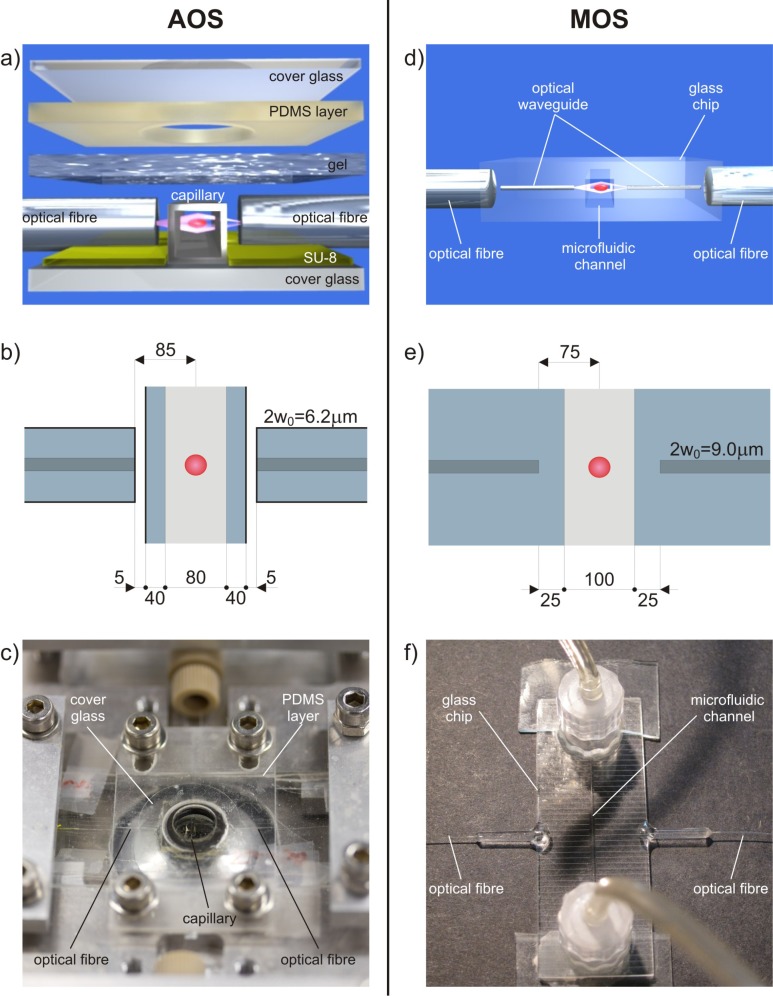
The setup alignment is usually guaranteed by assembling discrete optical and fluidic components on glass or polymeric substrates with the help of lithographically produced grooves [Figs. 1(a) –1(c)] [6]. Although the effectiveness of this approach has been widely demonstrated, it presents a few drawbacks. The presence of small discrete elements, which must be accurately mounted and aligned, makes the assembly difficult and cumbersome. In addition, this implementation is limited since it consists of only one straight microchannel and therefore it is not suitable for introducing additional valuable functions, e.g., mixing or sorting of the samples under test.
Fig. 1.
Comparison of experimental setups. (a) 3D rendering, (b) 2D schematic diagram of the optical trapping region including relevant dimensions in µm, and (c) picture of the assembled optical stretcher (AOS). (d-f) Corresponding panels for the monolithic optical stretcher (MOS). 2w0 indicates the mode field diameter of the fibre (b) and waveguide (e).
Combination on the same substrate of optical waveguides and microchannels for integrated lab-on-a-chip analysis is an extremely relevant research topic and several fabrication technologies have been proposed [12–16]. Recently, a handy, miniaturized and low-cost integrated chip has been demonstrated [17,18], in which microfluidic circuits and optical waveguides for cell trapping and stretching are fabricated in the same glass substrate by femtosecond laser micromachining [19]. Femtosecond laser technology [20] can provide direct writing of both optical waveguides [21] and microfluidic channels if combined with chemical etching [22,23], thus enabling the fabrication of optofluidic devices with novel layouts and functions [24,25]. The main advantages are extreme flexibility, three-dimensional capabilities and reliable, permanent alignment of optical and fluidic components with a precision better than 100 nm. At present the main limitation of these monolithic optical stretchers is due to a residual roughness [26] of the channel walls that induces optical distortions thus reducing the cell imaging quality. In addition, up to now, femtosecond laser fabricated optical stretchers have been tested only on red blood cells [17,18], which are easy to handle but represent only a limited niche of all the samples that can be analysed through an optical stretcher (in particular they are significantly smaller than most cells, and much more deformable).
In this work we present a new monolithic optical stretcher in which optical waveguides are fabricated by femtosecond laser micromachining in a commercial glass microfluidic chip [Figs. 1(d)–1(f)]. The imaging quality of the cells is greatly improved and reliable measurements of their deformation can be accomplished. Device validation has been performed on a biologically relevant leukaemia cell line, with typical size and stiffness for eukaryotic cells. The deformation results are compared with those obtained by means of a standard optical stretcher based on optical fibres aligned external to a microfluidic capillary. The analysis of the results obtained with the two alternative approaches allows us to confirm that the monolithic optofluidic chip is a valuable and reliable tool for optical stretching measurements and at the same time it provides significant data that can be used to improve its efficiency.
The validation of the monolithic chip fabricated by femtosecond lasers paves the way to the use of the unique versatility and 3D capability of this technology to develop the next generation of integrated optical manipulation devices, able to combine measurements of mechanical properties with other functions such as cell sorting or spectroscopic analyses.
2. Experiments
2.1. Fabrication of an assembled optical stretcher
The fabrication procedure of an assembled optical stretcher (AOS) is reported in detail elsewhere [6]. In summary, the optical and fluidic components to create the trap are aligned on a single SU-8 coated glass substrate [Fig. 1(a)]. A square glass capillary (with inner side lengths of 80 µm and outer lengths of 160 µm) is used to transport the cell suspension, while two optical fibres, single mode at a wavelength of about 1 µm (Hi-1060, Corning), are used to create the dual-beam optical trap. The glass substrate is patterned with an SU-8 photoresist structure using standard photolithographic techniques. This forms perpendicular gaps to align and hold in place the capillary and the two optical fibres. Fibres are outside of and perpendicular to the square capillary flow channel and they are placed in such a way as to shine the light in the lower part of the capillary section, since cells quickly settle at the channel bottom due to gravity. A thin slab of poly(dimethylsiloxane) (PDMS) with a 1.5 mm hole is placed over the setup so that the trap region is centred within the hole. The hole, which generously encompasses the trap region, is filled with index matching gel to reduce reflection of the laser beams and the imaging light. A glass coverslip is secured over the PDMS piece. A typical AOS is shown in Fig. 1(c). Such a system is considered the standard setup for cell optical stretching since it ensures high quality imaging and reliable flow control [6–9].
2.2. Fabrication of a monolithic optical stretcher
As previously mentioned, femtosecond laser micromachining (FLM) was already used for the fabrication of a monolithic optical stretcher (MOS) in a fused silica substrate [17,18]; microfluidic channel and optical waveguides were fabricated by the same femtosecond laser, with a subsequent step of chemical etching for the microchannel formation. This technique guarantees an almost perfect alignment between different optical and fluidic elements, enhanced robustness, portability and high flexibility for the implementation of further functionalities. Such systems have been demonstrated to be effective for trapping and stretching single red blood cells [17]. In addition, FLM capabilities enabled the fabrication of a square cross-section channel that strongly reduced the distortion of the trapping beams and of the cell imaging [18] with respect to channels with a circular cross-section obtained in the first demonstration of this chip [17]. However, the microchannel inner wall roughness (measured to be ~200 nm rms) still caused a difficult contour recognition when very small elongations of the cells were to be observed.
In recent years, the roughness issue in microchannels fabricated by femtosecond laser irradiation followed by chemical etching (FLICE) was addressed by using thermal post-treatments [26,27]. Work is in progress to validate this approach for our application.
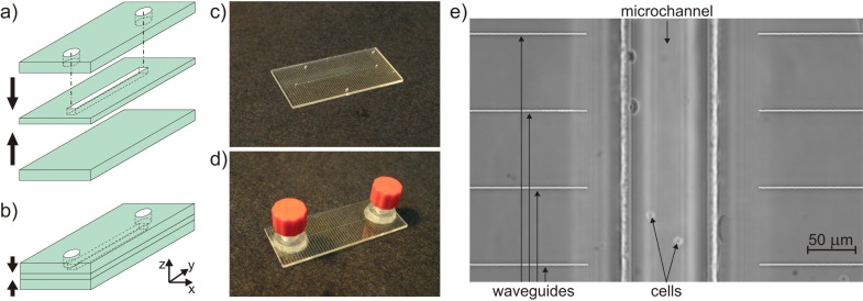
As an alternative, we explored the possibility of starting from commercial microfluidic devices made of glass. Standard photolithographic technologies for microchannel production lead to the fabrication of channels with a rounded trapezoidal cross-section; this is due to the etching process that starts at the surface and isotropically enlarges the access zone. Such a rounded shape is not optimal for the optical stretcher configuration since the two counter-propagating laser beams would encounter curved microchannel walls and would be refracted in different directions. For this reason, the channel cross-section must have a square/rectangular shape in order to avoid any lensing effect in imaging and any refraction effect of the two trapping beams. Such a square/rectangular shape is achievable with standard techniques only through deep reactive ion etching (DRIE) in fused silica. One of the drawbacks of this technology is that the channel depth is limited to ~50 µm due to technological constraints [28]; for red blood cells this would be acceptable but for most of the cells studied with the optical stretcher, e.g., cancer cells (~25-µm size), such a channel could lead to clogging by occasional cell clusters. Quite recently, a different technique, also based on femtosecond laser micromachining, was commercially introduced to produce channels with rectangular cross-section and allowing good imaging quality (Translume Inc.). A fused silica glass slide with a thickness of 250 µm is machined with the FLICE technique to obtain a through slot with vertical walls and arbitrary layout. Once the through slot is fabricated, it has to be sealed on both sides [Fig. 2(a) ]. For this purpose, two polished fused silica glass slides, with a thickness of 500 µm, are used as top and bottom covers; thermal bonding is performed to seal the channel. The top layer has two through holes aligned with the slot terminations to form the top access holes of the microchannel [Fig. 2(b)]. With such a fabrication technology the channel cross-section results perfectly rectangular with vertical side walls that present the same roughness previously mentioned (~200 nm rms), as they are obtained through the same FLICE process; however, in the optical stretcher configuration, the effect of this roughness is negligible for the waveguide mode quality [17]. In contrast, the top and bottom walls are of optical quality, thus allowing reliable cell imaging. The commercial microfluidic chip we used here is composed of a single straight channel: the channel has a 250-µm height (z-axis), determined by the middle glass thickness; it has a length of 40 mm (y-axis) and a width of 100 µm (x-axis). The external size of the chip is 50.8 mm × 25.4 mm × 1.3 mm [Fig. 2(c)]. In addition, the microchip can be equipped with two connectors at the channel reservoirs in order to easily plug in the external fluidic circuit [Fig. 2(d)].
Fig. 2.
Schematic representation of the microfluidic chip fabrication technique: a) three-layer technology with the central fused silica glass slide machined by femtosecond lasers and b) sealing of the channel with two polished glass slides. Image of the microfluidic chip c) without and d) with fluidic connections to the straight microchannel. e) Phase contrast microscope picture of femtosecond-laser-written optical waveguides integrated in the microfluidic chip facing the channel to create the MOS.
The microfluidic chip (already sealed and commercially available) can be upgraded to a MOS device, by the subsequent fabrication of pairs of opposite waveguides orthogonal to the channel through femtosecond laser micromachining; the waveguides deliver the laser light for cell trapping and stretching. The use of this commercial microfluidic chip on the one hand solves the surface quality issue, but, on the other hand, requires writing the optical waveguides at the considerable depth of ~730 µm below the chip surface. For this reason, waveguide writing has been specifically optimized. Optical waveguides of good quality and single-mode at 1-µm wavelength have been fabricated, with mode field diameter (at 1/e) of 9.0 µm, fibre-to-waveguide coupling losses of ~1.1 dB, and propagation losses of ~1.5 dB/cm. Several pairs of waveguides have been fabricated with different gaps between the waveguide end-faces and at different depth with respect to the channel. The waveguides chosen to perform trapping and stretching experiments are separated by 150 µm and are placed at about 18 µm from the channel bottom floor [Fig. 2(e)]. The chip edges are polished in order to achieve a good waveguide coupling to the optical fibre. The final waveguide length is 9.4 mm at each side.
To ensure stability, repeatability and portability of the MOS, we pigtailed two optical fibres to the chip edge [Fig. 1(f)]: the fibre is permanently glued to the waveguide following the standard procedure developed for photonic devices in telecommunications (typical additional losses ~0.5 dB) [29]. The pigtails have been tested with an input power up to 2 W per side for several minutes without showing any damage, thus proving to be suitable for cell stretching experiments at high optical power.
We indicate the power emitted by the optical fibre per side with PF and the power in the centre of the channel emitted by the waveguide per side with PC; PF is directly measurable knowing the laser power by a preliminary calibration of the experimental setup, while PC can be estimated from the characterized losses. The ratio between PC and PF is the so-called fibre-to-channel loss that represents the total insertion loss introduced by the waveguide between the optical fibre output and the centre of the channel where the cell will be trapped. We calculate the overall fibre-to-channel loss to be about 3 dB, taking into account also pigtailing losses.
2.3. Sample under investigation
HL60 cells are used to test the MOS. The HL60 is a myeloid cell line of human promyelocytic leukaemia cells. Promyelocytes are a neutrophil granulocyte precursor; granulocytes are a category of white blood cells. HL60 cells, and similar NB4 cells, are considered as reference sample in this study since they have extensively been studied by using the AOS [7,30], therefore their viscoelastic properties are very well characterized. For this reason, the experimental test on HL60 cells will allow us comparing the new MOS with the AOS. HL60 cells are measured in a phosphate buffer solution (PBS).
2.4. Experimental setup
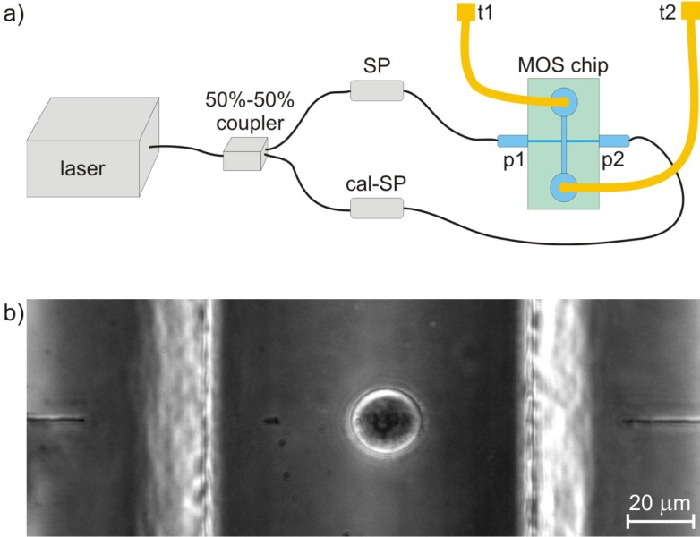
Thanks to the compactness of the MOS, the experimental setup is very simple [Fig. 3(a) ]. It includes an Yb-doped fibre laser (YLD-10-1064, IPG Photonics) giving an optical power up to 5.5 W at 1064 nm wavelength. The laser power is split through a 50%-50% fibre coupler and the two branches are directly spliced to the pigtailed fibres of the MOS chip. The losses of one of the fused splices are calibrated in order to balance the power in the middle of the fluidic channel from the two waveguides. The calibration is done by setting the trapping position of HL60 cells at the centre of the channel [Fig. 3(b)]. All the optical fibres used in such a setup are single mode at 1-µm wavelength (Hi-1060, Corning). The microfluidic channel reservoirs of the MOS are connected to poly(etheretherketone) (PEEK) tubing for driving the cell suspension. The optical stretcher is placed on an inverted transmission optical microscope equipped for phase contrast microscopy (TE2000-U, Nikon). Image capture is accomplished by a CCD camera. The flow control is accomplished by hydrodynamic pressure adjustments; this is done either by varying the relative heights at the tube terminations or by using a precise pressure pump (MFCS-8, Fluigent) connected to the PEEK tubes. Dedicated LabVIEW (National Instruments) software has been developed to perform several functions: (i) automatic recovery of the cell contour based on image analysis; (ii) elaboration of the collected data from trapping and stretching experiments; (iii) control of the laser power; (iv) control of the pump pressure in different channels.
Fig. 3.
(a) Schematic representation of the experimental setup for the MOS device: ‘SP’ indicates the fused splice, while ‘cal-SP’ indicates the splice used for trap calibration; ‘t1’ and ‘t2’ indicate the two PEEK tubing terminations; ‘p1’ and ‘p2’ are the two fibre pigtails. (b) Phase contrast microscope image of an HL60 cell trapped in the MOS; optical waveguides are also visible at the two sides.
Compactness and portability of the MOS device is clearly superior to that of the AOS [as also evident from Fig. 1(f)]. This is further demonstrated by the fact that the same device was shipped and reliably operated in all our three laboratory locations with highly reproducible results.
3. Results and discussion
3.1. Experimental results
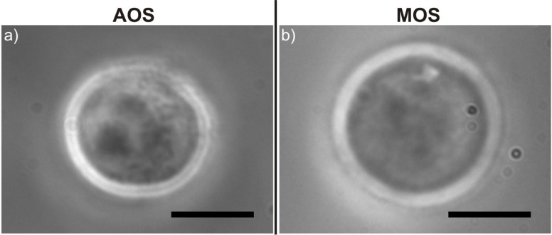
Once the HL60 cells are introduced into the MOS, the first analysis consists in a visual characterization. Cell imaging is clear and of very good quality: the MOS seems to provide at least as high quality images as the AOS; the contour is indeed more defined all along the cell membrane (Fig. 4 ). This effect can be explained by considering that the MOS has fewer interfaces in the imaging light path and therefore less distortion is introduced; in addition, the AOS has a top gel layer and likely slightly curved inner surfaces which are probably responsible for the small reduction in image quality.
Fig. 4.
Comparison between phase contrast microscope images of HL60 cells trapped using (a) the AOS and (b) the MOS device. Scale bars correspond to 10 µm.
HL60 cells have a diameter in the 16–23 µm range, and all the cells passing in the MOS device are efficiently trapped; this means that the optical waveguides are situated at the correct position with respect to the channel bottom floor.
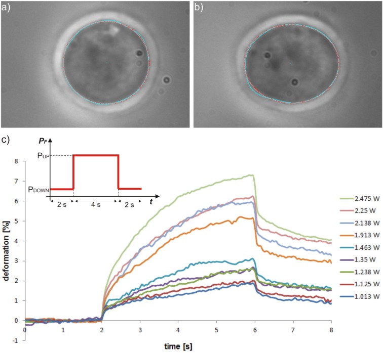
Stretching experiments are performed [Figs. 5(a) and 5(b)] by applying a step-like laser light power increase to the HL60 cells: the cell is trapped with a power PF equal to PDOWN = 180 mW applied for 2 s, then the step-like stimulus increases the power PF to a value PUP for 4 s, finally the power PF is decreased to the same initial PDOWN for other 2 s, and then the cell is released. Stretching experiments are performed for different PUP values in order to study the cell deformation properties for step stresses of different amplitude. For each value of PUP about 40–60 HL60 cells are stretched to collect enough data for a statistical analysis. Moreover, for each value of PUP the cell response is analysed in terms of deformation as a function of time. Cell deformation, or strain, ε(t) is defined as follows:
Fig. 5.
Phase contrast microscope images of (a) trapped and (b) stretched HL60 cell in a MOS stretching experiment with automatic contour recognition. (c) HL60 response to step-like increase in applied optical stress for different stretching power values. The inset represents the temporal shape of the step-like optical stimulus applied at the fibre output PF. The plot represents the average deformation of about 40–60 cells each as a function of time for different values of PUP of the step stimulus.
| (1) |
where l0 is the initial size along the beam axis of the trapped cell and l(t) is the cell size during the stretching process as a function of time. As shown in Fig. 5(c), the cell response has the typical behaviour given by a stretched viscoelastic body. From the analysis of such a curve many data can be derived, like rise time constant, maximum deformation, fall time constant, residual cell deformation, cell compliance, steady-state viscosity and plateau modulus [11]. All these data can be used to evaluate important mechanical properties of the cell cytoskeleton under investigation. As expected, the cell elongation increases for higher stretching powers, confirming that cells more complex than red blood cells, like HL60 cells, can be reliably stretched using the MOS. Moreover, the shape of the cell response to the optical stimulus follows the one already measured with the AOS [7].
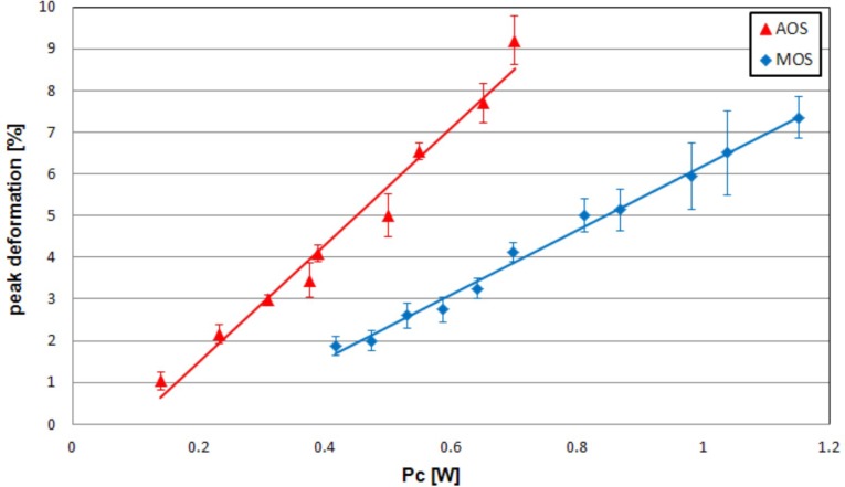
The simplest way to characterize the creep compliance of the cells as measured here is to compare the peak deformation: it is possible to derive the peak deformation reached for each value of PF = PUP with the MOS. The same experiment was previously accomplished with the AOS on HL60 cells. Taking into account the fibre-to-channel losses for both devices as previously measured, we can plot the peak deformation of the cell as a function of the power per side at the channel PC (Fig. 6 ). In both systems the plot is a straight line. However, the slopes of the straight lines for the two systems are different: in order to obtain the same peak deformation the AOS requires lower power if compared with the MOS, in particular PCAOS = 0.6 PCMOS. In other words, this indicates that the same power delivered at the microchannel in the two devices has a different efficiency in stretching the cells. To gain further insight we performed a careful theoretical modelling of the two systems as discussed in the following section.
Fig. 6.
Plot of the peak deformation of HL60 cells, for the MOS and AOS devices, as a function of the power PC delivered by each waveguide/fibre at the microchannel. The peak deformation is linearly proportional to the power for both the devices but with different slopes.
3.2. Theoretical analysis
With the aim of explaining why the same power PC in the channel provides different cell deformations in the AOS and MOS, we used the same exact analytical model for the computation of optical stresses induced on the surface of spheroidal objects already described in Ref. 31, based on generalized Lorenz-Mie theory, which confirms theoretical explanations of optical stretching based on ray optics [32,33]. Once the stress distribution on the cell is calculated, we indicate with σ0 the peak stress, i.e., the maximum force per area in the direction of the light beam axis, with ε(t) the cell strain as a function of time, and with GF the so-called geometric factor that takes into account the azimuthal distribution of stress and the architecture of the cell being deformed [11]. Now we can also introduce the tensile creep compliance D(t), which is the strain normalized by the stress applied and is a function of the cell intrinsic viscoelastic features only: for a given cell the compliance is determined regardless of the type of experimental elongation test performed. The compliance D(t) is defined as follows:
| (2) |
from which we can simply write:
| (3) |
where GGF is defined as the global geometric factor that includes all the geometrical features of the optical stretcher device; in particular, the GGF depends on the geometrical configuration of the optical stretcher (e.g., waveguide distance from the cell, waveguide mode size) that directly influences the relation between the optical power and the applied stress distribution on the cell. Given the optical power PC and the cell compliance D, the observed strain ε depends on the global geometric factor GGF of the system, i.e., they are linearly proportional. Thus, the GGF can be used as a figure of merit to evaluate the stretching efficiency of the device.
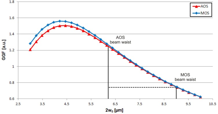
A theoretical analysis has been conducted to study the GGF of the two systems starting from their geometrical layout, with the aim of identifying the parameter(s) actually causing the 60% reduced efficiency of the MOS device compared to the AOS one. We calculate the GGF as a function of the mode field diameter 2w0 at the fibre (AOS)/waveguide (MOS) output. Two curves are plotted, one for each optical stretcher system, as shown in Fig. 7 . The curves overlap to a great extent: this means that differences in fibre/waveguide separation, channel size, fibre/waveguide position, and all the other geometrical factors are already well-optimized in the MOS. The main difference is the beam waist size: the mode field diameter at the fibre output in the AOS is smaller than the mode field diameter at the waveguide output in the MOS, 6.2 µm vs. 9.0 µm, respectively, which exactly accounts for the difference of about 60% in the GGF values. It is therefore evident that the stretching efficiency difference is due to the difference in beam waist sizes. This indicates the direction for future work: femtosecond laser micromachining will be optimized to write optical waveguides with smaller mode field diameter. In principle, the efficiency could be even improved with respect to the AOS if a mode size smaller than 6.2 µm at 1 µm wavelength were obtained. Reducing the mode size requires a higher refractive index change, which is not trivial with femtosecond laser waveguide writing; however, recent results [34,35] show that a significant mode size reduction is possible.
Fig. 7.
Plot of the GGF as a function of the beam waist size 2w0 for both AOS and MOS devices.
4. Conclusions
A monolithic optical stretcher has been fabricated in a commercial microfluidic chip by direct implementation of optical waveguides through femtosecond laser writing. Such an optical stretcher proved to be effective for optical trapping and stretching of cells that are more complex than red blood cells previously tested.
The system was successfully compared with the assembled optical stretcher, which is currently considered as the gold standard. Measurements on well-characterized HL60 cells revealed that the image quality in the monolithic optical stretcher is even slightly superior. Measurements of HL60 cell compliance were possible in the entire range of interest and the viscoelastic cell behaviour was found to be in very good agreement with previous analyses performed with the assembled system. Nevertheless, a lower stretching efficiency of the monolithic stretcher was shown; detailed studies attributed it to a larger beam waist size at the waveguide output caused by a larger mode field diameter of the waveguide. Future work will aim at enhancing the global stretching efficiency of the monolithic system by carefully designing the waveguide properties. Nevertheless, current performance already enables the use of this device with many biologically relevant samples and the robustness and portability will allow using it in clinical environments. In addition, further advanced functionalities can be integrated on-chip, e.g., waveguide couplers to directly monitor the optical power during stretching experiments, fluorescence measurements, Raman spectroscopy, as well as single cell sorting. This will pave the way to the realization of a lab-on-a-chip for extensive analyses and manipulation, including mechanical phenotyping by optical stretching at the single cell level.
Acknowledgments
We acknowledge partial financial support by Fondazione Cariplo through the project “Optofluidic chips for the study of cancer cell mechanical properties and invasive capacities.”
References and links
- 1.de Souza N., “Single-cell methods,” Nat. Methods 9(1), 35 (2011). 10.1038/nmeth.1819 [DOI] [Google Scholar]
- 2.Guck J., Ananthakrishnan R., Mahmood H., Moon T. J., Cunningham C. C., Käs J., “The optical stretcher: a novel laser tool to micromanipulate cells,” Biophys. J. 81(2), 767–784 (2001). 10.1016/S0006-3495(01)75740-2 [DOI] [PMC free article] [PubMed] [Google Scholar]
- 3.Radmacher M., “Measuring the elastic properties of living cells by the atomic force microscope,” Methods Cell Biol. 68, 67–90 (2002). 10.1016/S0091-679X(02)68005-7 [DOI] [PubMed] [Google Scholar]
- 4.Suresh S., “Biomechanics and biophysics of cancer cells,” Acta Mater. 55(12), 3989–4014 (2007). 10.1016/j.actamat.2007.04.022 [DOI] [PMC free article] [PubMed] [Google Scholar]
- 5.Guck J., Schinkinger S., Lincoln B., Wottawah F., Ebert S., Romeyke M., Lenz D., Erickson H. M., Ananthakrishnan R., Mitchell D., Käs J., Ulvick S., Bilby C., “Optical deformability as an inherent cell marker for testing malignant transformation and metastatic competence,” Biophys. J. 88(5), 3689–3698 (2005). 10.1529/biophysj.104.045476 [DOI] [PMC free article] [PubMed] [Google Scholar]
- 6.Lincoln B., Schinkinger S., Travis K., Wottawah F., Ebert S., Sauer F., Guck J., “Reconfigurable microfluidic integration of a dual-beam laser trap with biomedical applications,” Biomed. Microdevices 9(5), 703–710 (2007). 10.1007/s10544-007-9079-x [DOI] [PubMed] [Google Scholar]
- 7.Lautenschläger F., Paschke S., Schinkinger S., Bruel A., Beil M., Guck J., “The regulatory role of cell mechanics for migration of differentiating myeloid cells,” Proc. Natl. Acad. Sci. U.S.A. 106(37), 15696–15701 (2009). 10.1073/pnas.0811261106 [DOI] [PMC free article] [PubMed] [Google Scholar]
- 8.Maloney J. M., Nikova D., Lautenschläger F., Clarke E., Langer R., Guck J., Van Vliet K. J., “Mesenchymal stem cell mechanics from the attached to the suspended state,” Biophys. J. 99(8), 2479–2487 (2010). 10.1016/j.bpj.2010.08.052 [DOI] [PMC free article] [PubMed] [Google Scholar]
- 9.Remmerbach T. W., Wottawah F., Dietrich J., Lincoln B., Wittekind C., Guck J., “Oral cancer diagnosis by mechanical phenotyping,” Cancer Res. 69(5), 1728–1732 (2009). 10.1158/0008-5472.CAN-08-4073 [DOI] [PubMed] [Google Scholar]
- 10.Lai C.-W., Hsiung S.-K., Yeh C.-L., Chiou A., Lee G.-B., “A cell delivery and pre-positioning system utilizing microfluidic devices for dual-beam optical trap-and-stretch,” Sens. Actuators B Chem. 135(1), 388–397 (2008). 10.1016/j.snb.2008.08.041 [DOI] [Google Scholar]
- 11.Wottawah F., Schinkinger S., Lincoln B., Ebert S., Müller K., Sauer F., Travis K., Guck J., “Characterizing single suspended cells by optorheology,” Acta Biomater. 1(3), 263–271 (2005). 10.1016/j.actbio.2005.02.010 [DOI] [PubMed] [Google Scholar]
- 12.Mogensen K. B., Klank H., Kutter J. P., “Recent developments in detection for microfluidic systems,” Electrophoresis 25(21–22), 3498–3512 (2004). 10.1002/elps.200406108 [DOI] [PubMed] [Google Scholar]
- 13.Cleary A., Glidle A., Laybourn P. J. R., García-Blanco S., Pellegrini S., Helfter C., Buller G. S., Aitchison J. S., Cooper J. M., “Integrating optics and microfluidics for time-correlated single-photon counting in lab-on-a-chip devices,” Appl. Phys. Lett. 91(7), 071123 (2007). 10.1063/1.2772175 [DOI] [Google Scholar]
- 14.Vazquez R. M., Osellame R., Nolli D., Dongre C., van den Vlekkert H., Ramponi R., Pollnau M., Cerullo G., “Integration of femtosecond laser written optical waveguides in a lab-on-chip,” Lab Chip 9(1), 91–96 (2009). 10.1039/b808360f [DOI] [PubMed] [Google Scholar]
- 15.Sugioka K., Cheng Y., “Integrated microchips for biological analysis fabricated by femtosecond laser direct writing,” MRS Bull. 36(12), 1020–1027 (2011). 10.1557/mrs.2011.274 [DOI] [Google Scholar]
- 16.Hu Z., Glidle A., Ironside C. N., Sorel M., Strain M. J., Cooper J., Yin H., “Integrated microspectrometer for fluorescence based analysis in a microfluidic format,” Lab Chip 12(16), 2850–2857 (2012). 10.1039/c2lc40169j [DOI] [PubMed] [Google Scholar]
- 17.Bellini N., Vishnubhatla K. C., Bragheri F., Ferrara L., Minzioni P., Ramponi R., Cristiani I., Osellame R., “Femtosecond laser fabricated monolithic chip for optical trapping and stretching of single cells,” Opt. Express 18(5), 4679–4688 (2010). 10.1364/OE.18.004679 [DOI] [PubMed] [Google Scholar]
- 18.Bragheri F., Ferrara L., Bellini N., Vishnubhatla K. C., Minzioni P., Ramponi R., Osellame R., Cristiani I., “Optofluidic chip for single cell trapping and stretching fabricated by a femtosecond laser,” J. Biophotonics 3(4), 234–243 (2010). 10.1002/jbio.201000011 [DOI] [PubMed] [Google Scholar]
- 19.Osellame R., Maselli V., Martinez Vazquez R., Ramponi R., Cerullo G., “Integration of optical waveguides and microfluidic channels both fabricated by femtosecond laser irradiation,” Appl. Phys. Lett. 90(23), 231118 (2007). 10.1063/1.2747194 [DOI] [Google Scholar]
- 20.Gattass R., Mazur E., “Femtosecond laser micromachining in transparent materials,” Nat. Photonics 2(4), 219–225 (2008). 10.1038/nphoton.2008.47 [DOI] [Google Scholar]
- 21.Della Valle G., Osellame R., Laporta P., “Micromachining of photonic devices by femtosecond laser pulses,” J. Opt. A, Pure Appl. Opt. 11(1), 013001 (2009). 10.1088/1464-4258/11/1/013001 [DOI] [Google Scholar]
- 22.Marcinkevičius A., Juodkazis S., Watanabe M., Miwa M., Matsuo S., Misawa H., Nishii J., “Femtosecond laser-assisted three-dimensional microfabrication in silica,” Opt. Lett. 26(5), 277–279 (2001). 10.1364/OL.26.000277 [DOI] [PubMed] [Google Scholar]
- 23.Vishnubhatla K. C., Bellini N., Ramponi R., Cerullo G., Osellame R., “Shape control of microchannels fabricated in fused silica by femtosecond laser irradiation and chemical etching,” Opt. Express 17(10), 8685–8695 (2009). 10.1364/OE.17.008685 [DOI] [PubMed] [Google Scholar]
- 24.Osellame R., Hoekstra H. J. W. M., Cerullo G., Pollnau M., “Femtosecond laser microstructuring: an enabling tool for optofluidic lab-on-chips,” Laser Photonics Rev. 5(3), 442–463 (2011). 10.1002/lpor.201000031 [DOI] [Google Scholar]
- 25.Schaap A., Bellouard Y., Rohrlack T., “Optofluidic lab-on-a-chip for rapid algae population screening,” Biomed. Opt. Express 2(3), 658–664 (2011). 10.1364/BOE.2.000658 [DOI] [PMC free article] [PubMed] [Google Scholar]
- 26.He F., Cheng Y., Xu Z., Liao Y., Xu J., Sun H., Wang C., Zhou Z., Sugioka K., Midorikawa K., Xu Y., Chen X., “Direct fabrication of homogeneous microfluidic channels embedded in fused silica using a femtosecond laser,” Opt. Lett. 35(3), 282–284 (2010). 10.1364/OL.35.000282 [DOI] [PubMed] [Google Scholar]
- 27.He F., Lin J., Cheng Y., “Fabrication of hollow optical waveguides in fused silica by three-dimensional femtosecond laser micromachining,” Appl. Phys. B 105(2), 379–384 (2011). 10.1007/s00340-011-4520-5 [DOI] [Google Scholar]
- 28.M. J. Madou, Fundamentals of Microfabrication: the Science of Miniaturization (CRC Press, Boca Raton, FL, 2002). [Google Scholar]
- 29.Murphy E., Rice T., McCaughan L., Harvey G., Read P., “Permanent attachment of single-mode fiber arrays to waveguides,” J. Lightwave Technol. 3(4), 795–799 (1985). 10.1109/JLT.1985.1074268 [DOI] [Google Scholar]
- 30.Chalut K. J., Ekpenyong A. E., Clegg W. L., Melhuish I. C., Guck J., “Quantifying cellular differentiation by physical phenotype using digital holographic microscopy,” Integr. Biol. (Camb.) 4(3), 280–284 (2012). 10.1039/c2ib00129b [DOI] [PubMed] [Google Scholar]
- 31.Boyde L., Chalut K. J., Guck J., “Interaction of Gaussian beam with near-spherical particle: an analytic-numerical approach for assessing scattering and stresses,” J. Opt. Soc. Am. A 26(8), 1814–1826 (2009). 10.1364/JOSAA.26.001814 [DOI] [PubMed] [Google Scholar]
- 32.Guck J., Ananthakrishnan R., Moon T. J., Cunningham C. C., Käs J., “Optical deformability of soft biological dielectrics,” Phys. Rev. Lett. 84(23), 5451–5454 (2000). 10.1103/PhysRevLett.84.5451 [DOI] [PubMed] [Google Scholar]
- 33.Boyde L., Ekpenyong A., Whyte G., Guck J., “Comparison of stresses on homogeneous spheroids in the optical stretcher computed with geometrical optics and generalized Lorenz-Mie theory,” Appl. Opt. (to be published). [DOI] [PubMed] [Google Scholar]
- 34.Eaton S. M., Ng M. L., Osellame R., Herman P. R., “High refractive index contrast in fused silica waveguides by tightly focused, high-repetition rate femtosecond laser,” J. Non-Cryst. Solids 357(11–13), 2387–2391 (2011). 10.1016/j.jnoncrysol.2010.11.082 [DOI] [Google Scholar]
- 35.Bragheri F., Minzioni P., Martinez Vazquez R., Bellini N., Paiè P., Mondello C., Ramponi R., Cristiani I., Osellame R., “Optofluidic integrated cell sorter fabricated by femtosecond lasers,” Lab Chip 12(19), 3779–3784 (2012). 10.1039/c2lc40705a [DOI] [PubMed] [Google Scholar]


