Abstract
A significant challenge in engineering molecular motors is designing mechanisms to coordinate the motion between multiple domains of the motor so as to bias random motion. For bipedal motors, this challenge takes the form of coordinating the movement of the biped’s legs, so they can move in a synchronized fashion. To address this problem, we have constructed an autonomous DNA bipedal nanorobot that coordinates the action of its two legs by coupling room temperature thermal energy with the catalysis of metastable DNA fuel strand hybrids. This coupling leads to a chemically ratcheted unidirectional walk along a DNA track. By crosslinking aliquots of the walker covalently to its track in successive walking states, we demonstrate that the walker can complete a full walking cycle on a track whose length could be extended for longer walks.
A variety of DNA-based walker (1–6) systems have been reported. However, none of them has demonstrated domains that can feed information cyclically from one to the other, so as to use thermal energy for coordinated and directed motion. Such domain coordination, biology demonstrates, is the starting point for building complex molecular motors and machinery that can be powered by thermal energy and regulated by chemical energy. Biological bipedal-like motors, such as kinesin (7), myosin (8), and dynein (9) are all examples of coordinated activity between two motor domains, in concert with thermal energy, chemical fuel, and substrates, that produce directed and complex mechanical behavior. Indeed, ensembles of kinesin, dynein and myosin, acting cooperatively, form the basis for the movements of flagella, cilia, and muscles (9). This precedent suggests that multiple synthetic bipeds could also be used to construct complex molecular machinery and collectively produce controlled movement over multiple length scales. To achieve this goal, mechanisms for synthetic motor domain coordination need to be devised.
Here, we present a unidirectional autonomous bipedal walker, made solely of DNA. This device displays true motor behavior by coordinating the stepping cycle of its two legs as it walks along a DNA track; it does this by having its leading leg catalyze the release of its trailing leg. The release signal, sent from the leading leg to the trailing leg, is mediated by metastable DNA fuel strand complexes (5, 6, 10, 11). In each step the walker makes, its leading leg initiates a cascading reaction between complementary metastable DNA stem-loop structures. This reaction leads to the release of the trailing leg, and an overall increase in the number of base pairs that the system forms. Green et al. recently showed how the back leg of a DNA biped could be biased for forward movement by its leading leg on a single-stranded DNA substrate that lacks a robust structure (6). They outline an intriguing leg coordination design that in principle is capable of directed motion. In our experiments we demonstrate the operation of an actual biped that completes a fully coordinated stepping cycle on a linear stiff track, thereby exhibiting autonomous and directed molecular motion.
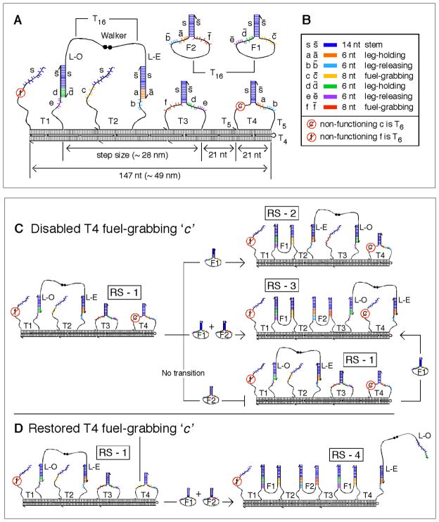
Our system is comprised of 21 DNA strands. As Fig. 1A shows, the walker is a single strand of DNA containing a 5′, 5′ linkage in the middle; one leg is called Leg-Even (L-E) and the other is called Leg-Odd (L-O). It walks upon a linear double-crossover (DX) (12) track, which is designed to be approximately 49 nm long, and has a persistence length ca. 100 nm (13). The track is assembled from eighteen strands, four of which are metastable stem-loop structures, T1, T2, T3, and T4, that function both in the operation of the device and as structural elements in the track (SOM text S1 and Fig. S1). Two metastable hairpin fuel strands, F1 and F2, float freely in solution. To distinguish them from the stationary track stem-loops, we refer to the freely-floating fuel strands as hairpins.
Fig. 1.
(A) Cartoon of the DX track structure with the walker on it. The walker is shown on stem-loops T1 and T2. The walker’s 5′-5′ link is denoted by two black dots, and its 3′ ends by half arrows. T16 denotes flexible poly-thymidine linkers on the walker and two fuel hairpins F1 and F2. Two T5 regions provide flexibility at the base of the track stem-loops. All the binding sites are labeled with lowercase letters and complementary sequences are capped with a bar. The two fuel-grabbing sequences f and c on T1 and T4 respectively are not functional. (B) Color-coding and names of the binding sites. (C) Transitions made with a non-functional T4 fuel-grabbing sequence c. The walker is programmed to take two steps from RS-1 to RS-3 with the addition of F1 and F2 simultaneously (middle transition). A single step is made from RS-1 to RS-2 with the addition of F1 alone (top transition). With the addition of F2 alone, the walker does not move, and only with the further addition of F1 does the walker make the transition from RS-1 to RS-3 (bottom transition). (D) With the T4 fuel-grabbing sequence c restored, the walker transitions to RS-4, incorporating another F1 into the track, thereby kicking L-O off of T3.
All the reactions are designed around six ‘toehold’ (14) sequences on the loop regions of the track stem-loops (Fig. 1A and 1B) (See SOM text S2 for a discussion of the sequence design). There is leg-holding site d, a toehold binding site for L-O on T1 and T3, and leg-holding site a, another toehold binding site for L-E on both T2 and T4. There are fuel-grabbing sites c and f, which are toeholds for the activation of fuel strands F1 and F2. Fuel-grabbing site c is on T2 and on T4, while fuel-grabbing site f is on T1 and on T3. Finally, there are leg–releasing sites e and b; these are toeholds for the activated fuel molecules F1 and F2 that release walker legs L-O and L-E, respectively.
By controlling these toehold interactions kinetically, we show that the walker can take two steps autonomously from what we call Resting-State 1 (RS-1) (Fig. 1C, left) to Resting-State 3 (RS-3) with the simultaneous addition of fuel strands F1 and F2 (Fig. 1C - middle transition). We also show the one step intermediate transition from RS-1 to Resting-State 2 (RS-2) when only F1 is added (Fig. 1C - top transition). To demonstrate control of the system and its dependence on both fuel strands, we show that when F2 alone is added no transition takes place, and that only when F1 is further added does the walker make the transition from RS-1 to RS-3 (Fig. 1C - bottom and right transitions). In the experimental demonstrations of the three transitions described above, the system was closed; this was achieved by changing both fuel-grabbing site f on T1, and fuel-grabbing site c on T4 to tracts containing only poly-thymidine, thereby rendering them both non-specific and inactive. We also show that when the sequence of fuel-grabbing site c on T3 is restored, the walker transitions to Resting-State 4, RS-4, incorporating one more F1 molecule into the track (Fig. 1D).
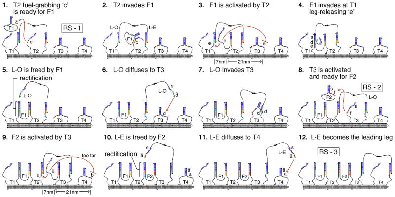
Fig. 2 depicts the biped’s autonomous transition from RS-1 to RS-3 in 12 sequential steps. Steps 1–5 depict the release of L-O from T1 with the incorporation of F1 into the track. The fuel strand that releases the walker biases or rectifies the walker’s forward movement by creating a more stable duplex with the stem-loop that was holding the released leg. The catalyzed release of the trailing leg by the leading leg is shown in steps 6–10: The leading leg (L-O) first diffuses to, and activates its target stem-loop (T3) (steps 6–8); the activated stem-loop (T3) then activates and places its fuel hairpin (F2) into position to free the trailing leg (L-E) of the walker from its stem-loop (T2) (steps 9 and 10). The activated fuel strand (F2) has limited single-stranded flexibility (15, 16), and it is placed 3 times closer (7 nm vs. 21 nm) to its complementary stem-loop (T2) (holding the trailing leg of the walker), than to the stem-loop (T4) one site ahead (step 9). The two metastable topologies the walker forms with the track, when either one or two legs are attached, protect the leg-releasing sequences directly beneath each leg from being accessed by their fuel strands prematurely (SOM text S3 and Fig. S3). After one step of the walker, an overall free energy gain corresponding to 20 base pairs occurs, with the incorporation of one fuel molecule into the track: 8 for the fuel-grabbing region; and 12 for the leg-holding and leg-releasing region.
Fig. 2.
Transition from RS-1 to RS-3. In 12 sequential frames, this cartoon depicts the biped taking 2 steps. The leading-leg L-O catalyzing the release of the trialing-leg L-E) is depicted in steps 6–10. Central to directionally biasing the biped, steps 3 and 9, show how the activated fuel strands are spatially restricted to act on the stem-loop 7 nm away rather than the stem-loop 21 nm away.
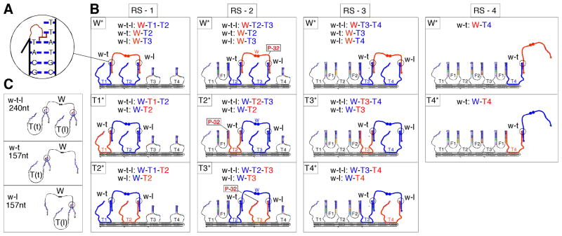
We tracked the progress of the walker by covalently crosslinking aliquots of it to the track as fuel was added, and visualizing the constituent strands of the products in autoradiograms produced from either super-denaturing (17) or non-denaturing polyacrylamide gel electrophoresis (PAGE). Each track stem-loop was synthesized with a psoralen molecule on its 3′ end; consequently, the track stem-loops crosslink across their duplexes when the system is exposed to UV light (18) (Fig. 3A). Five experiments were run in parallel: W*; T1*; T2*; T3*; and T4*. In each experiment, only one of the strands was radioactively labeled: W* (walker); T1* (track stem-loop T1); T2* (track stem-loop T2); T3* (track stem-loop T3); and T4* (track stem-loop T4). Fig. 3B shows the crosslinking reactions that take place in the four resting states RS-1, RS-2, RS-3, and RS-4, of the track, and for each resting state, the experiments in which the walker/stem-loop crosslink products are visible.
Fig. 3.
Psoralen crosslinking and 32P labeling. (A) A detailed picture of the UV activated psoralen crosslinking reaction between the track stem-loops and the walker. The psoralen on the stem-loops covalently links to the thymidines on the walker’s legs just outside the duplex formed by the stem-loops and the walker’s legs. (B) Visualizing the crosslink products with 32P. The three crosslinked products w-t (walker linked to the stem-loop on its trailing leg), w-l (walker linked to the stem-loop on its leading leg), and w-t-l (walker linked on both its trailing and leading leg) are shown forming in each experiment (W*, T1*, T2*, T3* and T4*) that they are visible for each resting state (RS-1, RS-2, RS-3, RS-4) of the system. The radioactive strand is drawn in bold red and the non-radioactive strands that are part of the crosslinked complex are drawn in bold blue. The constituent components of the products formed are listed in each box. (C) Denatured topologies and size of the three walker-stem-loop crosslink products w-t, w-l, and w-t-l.
The products of the walker crosslinked to the track stem-loops will appear as two higher molecular weight bands on super-denaturing PAGE (19). A molecule migrates on a denaturing gel as a function of both its size and its topology (20). The upper band consists of the walker crosslinked to two stem-loops, one on its trailing leg, and one on its leading leg (Fig. 3C; w-t-l product: for (w)alker - (t)railing leg - (l)eading leg). The lower band contains the walker crosslinked to one stem-loop, either on its trailing or on its leading leg (Fig. 3C; w-t and w-l products respectively). The formation and global state changes of the track are visible in non-denaturing gels, and the position of the walker on the track is visible in super-denaturing gels.
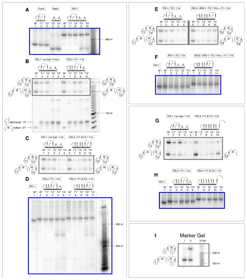
After an initial annealing step in which the two halves of the track (Fig. 4A, lanes 1–5) were combined to assemble the whole track (SOM text S4 and S5, Fig. S5 and S6), all 5 radioactive track species W*, T1*, T2*, T3*, and T4*, co-localized on a gel to form one band (Fig. 4A, lanes 6 to 10). To show that the assembled track was consistent with state RS-1, we exposed aliquots of all 5 track solutions to 366 nm light, capturing the position of the walker. A super-denaturing gel of these 5 mixtures, shows the walker crosslinked almost entirely to T1 and T2 (Fig. 4B, lanes 1 to 5). Pictured on the left hand side of the gel, the resulting crosslinked products are: w-t-l (W-T1-T2) in experiments W* (lane 1), T1* (lane 2) and T2* (lane 3); w-t (W-T1) in experiments W* and T1*; and w-l (W-T2) in experiments W* and T2*. [For an explanation of the secondary products seen in middle of the gel, see SOM text S6 and Fig. S7–S10]
Fig. 4.
Autoradiogram analysis of the walking cycle. Non-denaturing gels (all 4%) are outlined in blue and super-denaturing gels (all 10%) are outlined in grey. Target products for the two states shown in each super-denaturing gel are drawn on the left and right hand side of each gel. The bands in the marker lanes that are labeled, are labeled by the number of nucleotides they correspond to. (A) Non-denaturing gel verifying formation of the track. The front half of the track (lanes 1–3) was annealed to the back half (lanes 4, 5) to make five species of the complete track or RS-1 (lanes 6–7) where only one strand was radioactive in each species. (B) Super-denaturing gel showing the walkers position in RS-1 at 0 hrs (lanes 3–7) and then in RS-2 (lanes 8–12) with the addition of F1 after 1 hour. [The box inside the gel outlines the walker-stem-loop crosslink products. See SOM text S6 and Fig. S7–S10 for a detailed explanation of the secondary products seen on the super-denaturing gels, as well as complete images of the super denaturing gels] (C) Super-denaturing gel verifying the transition to RS-3 (lanes 8–12) with the addition of F1 and F2, and no transition with no fuel added (lanes 3–7), both within an hour. (D) Non-denaturing gel verification of (B) and (C), showing the global state changes in the five experiments for RS-1 (lane 1), RS-2 (lanes 2–6) and RS-3 (lane 7–11). (E) Composite super-denaturing gel showing the track remained in RS-1 while sitting in solution with F2 for 1 hour (lanes 1–5), and then transitioned to RS-3 when F1 was added to the mixture (lanes). (Note: the grey line separates data from two different gels. (SOM Fig. S9)) (F) Non-denaturing gel of (E), showing co-localization of the RS-1 track with no fuel and the track in solution with F2, and then the transition to RS-3 when F1 was further added. (G) Super-denaturing gel verifying the transition to RS-4 (lanes 6–10) with the addition of F1 and F2, and verification that the system remained in RS-1 (lanes 3–7) with no fuel added (lanes), both within an hour. (H) Non-denaturing gel verification of (G), showing the global state changes in the five experiments for RS-1 (lane 1), RS-2 (lanes 2–6) and RS-4 (lane 7–11). (I) Marker gel showing the position of the w-t, w-l, and w-t-l products on a super-denaturing gel. [Complete pictures of the non-denaturing gels are outlined in SOM text S7 and Fig. S11].
To show that the walker transitioned from RS-1 to RS-2 with the addition of F1, we added F1 to aliquots of all 5 assembled track solutions. After 1 hour, the walker clearly transitioned and crosslinked to T2 and T3 (Fig. 4B, lanes 6–10). It is clear that both w-t-l (W-T1-T2) and w-t (W-T1) were greatly reduced in experiment T1* (compare lane 2 and lane 7) and w-t-l (W-T2-T3) and w-l (W-T3) appeared in experiment T3* (compare lane 4 and lane 9), consistent with the transition from RS-1 to RS-2. The target products W-T2-T3, W-T2, and W-T3 are pictured on the right of the gel. [A 1 hour time interval was used in all the experiments. This was an ideal time period for handling the five radioactive track versions simultaneously, because all associated denaturing and nondenaturing experiments were conducted in parallel from one stock solution (19).]
To show that the walker took two steps autonomously from RS-1 to RS-3 upon the addition of F1 and F2, we added both fuel strands simultaneously. After 1 hour, a majority of the walker crosslinked to T3 and T4, consistent with the transition to RS-3 (Fig. 4C, lanes 6 to 10). As a control, we let aliquots of the track sit without fuel for the same hour: In this experiment, the walker remained on T1 and T2 (lanes 1 to 5), demonstrating that on the time scale of an hour it was the addition of fuel that drove the movement of the walker, and not random diffusion. Quantitation of band intensities established the stepping efficiency of the walker to be 74% for each step of the walker (SOM text S8, Fig. S12 and Table S1).
As the walker moved and the track picked up fuel molecules, the molecular weight of the walker and track increased, and its 3D shape changed; as a result its mobility decreased. These changes can be seen as mobility shifts in a non-denaturing gel (Fig. 4D). In lane 1, an aliquot of experiment W* in state RS-1 acts as a marker. When F1 alone was added, a gel shift occurred reflecting the incorporation of one fuel molecule during the transformation to RS-2 (lanes 2 to 6). When both fuel molecules were added, a larger gel shift was observed, reflecting the incorporation of two fuel molecules during the transformation to RS-3 (lanes 7 to 11). Uniform behavior is seen in all five experiments. No visible amount of free walker, or of track multimers can be seen in Fig. 4D; this finding strongly suggests that the walkers began and ended their walks on the same track, and coupled their legs intra-molecularly.
Further demonstrating control of the system, we added F2 alone to the track for one hour, and found that the walker primarily remained on and crosslinked to T1 and T2, (Fig. 4E, lanes 1 to 5). When we added F1 to this solution containing the track and F2 and left it to react for another hour, the walker was found crosslinked to T3 and T4 (lanes 6 to 10), again demonstrating that it transitioned from the RS-1 structure to the RS-3 structure only when both fuel molecules were present. A non-denaturing gel (Fig. 6F) also shows that the track that sat in solution with F2 (lanes 2 to 6), co-localized with the track to which no fuel was added (lane 1), and then shifted after F1 was added to this mixture (lanes 7 to 11).
The transition to RS-4 is shown in Figs. 4G and 4H. The data in this case indicate that the walker crosslinked primarily to T4 upon the addition of F1 and F2, or that the distribution of product shifted to the w-l product (Fig. 4G, lanes 6–10). Fig. 4H shows uniform transitioning in the native state. This result further verifies that the system works as designed and that the fuel-grabbing sequences can control the walker’s progress.
We have demonstrated the activity of a DNA molecular motor that uses leg coordination to achieve directed bipedal motion in a “burnt bridges” Brownian ratchet type mechanism (21, 22). This mechanism allows the walker to sequentially and dynamically hybridize molecules (the fuel hairpins) onto the track, according to the code of the track. Such a capability in a molecular automaton is reminiscent of the ribosome and DNA or RNA polymerase (23). Indeed, the leg-holding sequences are uncoupled from the fuel-grabbing sequences. Thus, in principle, a track could be encoded to hybridize with an arbitrary number of fuel molecules before the walker returned to the beginning of the fuel cycle. As noted above, all transitions were performed during 1 hour time intervals (19), hence detailed information about the reaction rates of the system are not available from this study. This demonstration of molecular coordination is a step toward the development of more processive and autonomous behavior in nanorobotic systems containing synthetic molecular motors, whether they are made from DNA, or other polymeric materials (24). We expect that this nanorobot can be used to direct a variety of processes in nanotechnology. These could include sequential synthetic systems and assembly line processes, programmed chemistry and unique forms of molecular choreography. Biology shows that the collective movement of molecular motors acting in concert can lead to the effective control of motion from the nanoscale to the macroscale. This capability illustrates the value of mimicking biological mechanisms to control molecular motion.
Supplementary Material
References
- 1.Sherman WB, Seeman NC. Nano Lett. 2004;4:1203. [Google Scholar]
- 2.Shin JS, Pierce NA. J Am Chem Soc. 2004;126:10834. doi: 10.1021/ja047543j. [DOI] [PubMed] [Google Scholar]
- 3.Tian Y, He Y, Chen Y, Yin P, Mao C. Angew Chem Int Edn. 2005;44:2. doi: 10.1002/anie.200500703. [DOI] [PubMed] [Google Scholar]
- 4.Pei R, et al. J Am Chem Soc. 2006;128:12693. doi: 10.1021/ja058394n. [DOI] [PubMed] [Google Scholar]
- 5.Yin P, Choi HMT, Calvert CR, Pierce NA. Nature. 2008;451:318. doi: 10.1038/nature06451. [DOI] [PubMed] [Google Scholar]
- 6.Green SJ, Bath J, Turberfield AJ. Phys Rev Lett. 2008;101:238101. doi: 10.1103/PhysRevLett.101.238101. [DOI] [PubMed] [Google Scholar]
- 7.Svoboda K, et al. Nature. 1993;365:721. doi: 10.1038/365721a0. [DOI] [PubMed] [Google Scholar]
- 8.Mehta AD. Nature. 1999;400:590. doi: 10.1038/23072. [DOI] [PubMed] [Google Scholar]
- 9.Vale RD. Cell. 2003;112:467. doi: 10.1016/s0092-8674(03)00111-9. [DOI] [PubMed] [Google Scholar]
- 10.Turberfield AJ, et al. Phys Rev Lett. 2003;90:118102. doi: 10.1103/PhysRevLett.90.118102. [DOI] [PubMed] [Google Scholar]
- 11.Bois JS, et al. Nucleic Acids Res. 2005;33:4090. doi: 10.1093/nar/gki721. [DOI] [PMC free article] [PubMed] [Google Scholar]
- 12.Fu TJ, Seeman NC. Biochemistry. 1993;32:3211. doi: 10.1021/bi00064a003. [DOI] [PubMed] [Google Scholar]
- 13.Sa-Ardyen P, Vologodskii AV, Seeman NC. Biophys J. 2003;84:3829–3837. doi: 10.1016/S0006-3495(03)75110-8. [DOI] [PMC free article] [PubMed] [Google Scholar]
- 14.Yurke B, Turberfield AJ, Mills JAP, Simmel FC, Neumann JL. Nature. 2000;406:605. doi: 10.1038/35020524. [DOI] [PubMed] [Google Scholar]
- 15.Mills JB, Vacano E, Hagerman PJ. J Mol Biol. 1999;285:245. doi: 10.1006/jmbi.1998.2287. [DOI] [PubMed] [Google Scholar]
- 16.Smith SB, Cui YJ, Bustamante C. Science. 1996;271:795. doi: 10.1126/science.271.5250.795. [DOI] [PubMed] [Google Scholar]
- 17.Fischer SG, Lerman LS. Cell. 1979;16:191. doi: 10.1016/0092-8674(79)90200-9. [DOI] [PubMed] [Google Scholar]
- 18.Gia O, Magno SM, Garbesi A, Colonna FP, Palumbo M. Biochemistry. 1992;31:11818. doi: 10.1021/bi00162a021. [DOI] [PubMed] [Google Scholar]
- 19.Material and methods (SOM text S9) are available as supporting online material.
- 20.Fu TJ, Tse-Dinh YC, Seeman NC. J Mol Biol. 1994;236:91. doi: 10.1006/jmbi.1994.1121. [DOI] [PubMed] [Google Scholar]
- 21.Mai J, Sokolov IM, Blumen A. Phys Rev E. 2001;64:011102. doi: 10.1103/PhysRevE.64.011102. [DOI] [PubMed] [Google Scholar]
- 22.Saffarian S, Collier IE, Marmer BL, et al. Science. 2004;306:108. doi: 10.1126/science.1099179. [DOI] [PubMed] [Google Scholar]
- 23.Shapiro E, Benenson Y. Sci Am. 2006;294:44. [PubMed] [Google Scholar]
- 24.Kay ER, Leigh DA, Zerbetto F. Angew Chem Int Ed. 2007;46:72. doi: 10.1002/anie.200504313. [DOI] [PubMed] [Google Scholar]
- 25.We would like to thank Chengde Mao, Hao Yan and Natasha Jonoska for critical reading of the manuscript. This research has been supported by grants to NCS from the National Institute of General Medical Sciences, the National Science Foundation, the Army Research Office, the NYNBIT program of the Department of Energy and the W.M. Keck Foundation.
Associated Data
This section collects any data citations, data availability statements, or supplementary materials included in this article.


