Abstract
We present an order N method for calculating electrostatic interactions that has been integrated into the molecular dynamics portion of the TINKER Molecular Modeling package. This method, introduced in a previous paper [J. Chem. Phys. 131 (2009) 154103] and termed the Image-Charge Solvation Model (ICSM), is a hybrid electrostatic approach that combines the strengths of both explicit and implicit representations of the solvent. A multiple-image method is used to calculate reaction fields due to the implicit part while the Fast Multipole Method (FMM) is used to calculate the Coulomb interactions for all charges, including the explicit part. The integrated package is validated through test simulations of liquid water. The results are compared with those obtained by the Particle Mesh Ewald (PME) method that is built in the TINKER package. Timing performance of TINKER with the integrated ICSM is benchmarked on bulk water as a function of the size of the system. In particular, timing analysis results show that the ICSM outperforms the PME for sufficiently large systems with the break-even point at around 30,000 particles in the simulated system.
Keywords: Method of images, reaction field, electrostatic interaction, TINKER
1 Introduction
In Ref. [1], we introduced a new solvation method for calculating electrostatic interactions in computer simulations of biomolecules in aqueous solutions. This method, termed the image-charge solvation model (ICSM), is a hybrid solvation model that combines the strengths of both explicit and implicit solvent representations. In this model, solute molecules are placed in a central spherical cavity filled with explicit water, while the solvent outside the cavity is modeled as a dielectric continuum whose effect on the solute is treated through reaction field corrections. For improved computational efficiency, an accurate and efficient multiple-image charge method is used to compute these reaction field corrections [1–4], and at the same time the adaptive fast multipole method (FMM) [5–8] is employed to calculate the electrostatic force field inside the simulation box, including the direct Coulomb interactions between the explicit particles. When there are N charges inside the cavity, the use of the FMM will result in a speedup from O(N log N) for the Particle Mesh Ewald (PME) to only O(N) operations. The ICSM was originally tested systematically using an in-house program written specifically for use with bulk water [1], and later it was further tested through simulations of ions solvated in water using the modified in-house program [9]. For both cases, it has been found that, by using an optimal set of model parameters, the ICSM can faithfully reproduce many known properties of the simulated biological systems.
In order to apply the ICSM as a general tool to more complicated molecules such as proteins and viruses, we have integrated it into the TINKER Molecular Modeling package [10–16]. Generally speaking, the TINKER molecular modeling software is a complete and general package for molecular mechanics and dynamics, with some special features for biopolymers. It is a free, open-source software that was written and is maintained by Professor J. Ponder’s group at the Washington University. The package contains different molecular force-field parameter sets including AMBER, CHARMM 19, 22, and 27, among several others [10]. The TINKER package has been extensively tested on multiple platforms. Its programs are written in Fortran and can be easily modified. In our case, we have integrated the ICSM into the molecular dynamics portion of the TINKER package.
The paper is organized as follows. In Section 2, the ICSM and its theoretical background are briefly reviewed. Next in Section 3, details regarding how to install as well as how to run the integrated package are discussed. A brief description of the program structure is also presented there. Then in Section 4 the integrated package is tested through simulations of liquid water and the results are analyzed. Also included in this section are some timing analysis results. Finally, concluding remarks are presented in Section 5.
2 Overview of the ICSM and its theoretical background
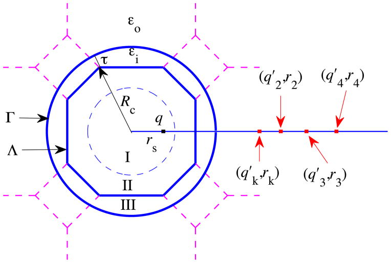
The ICSM was described in detail in Ref. [1]. Here we give only a brief overview of the most important features of the model for consistency. The model itself can be schematically illustrated by Fig. 1. A regular truncated octahedron (TO) Λ is employed as the main simulation box. The central part of the box, marked as Region I, aims to accommodate the solute molecule under study, while the remaining part of the box (including Region II and the area in Region I not occupied by the solute molecule) is filled with solvent. The solute and the solvent molecules inside the main simulation box Λ are to be treated in atomic detail. Region III represents a buffer zone whose purpose is to eliminate or reduce the surface effects that would otherwise be induced by the sharp boundary between explicit and implicit solvents. The solvent molecules in Region III are just periodic images of the solvent particles in Region II, defined as in the usual periodic boundary condition with respect to the TO Λ for long range electrostatic calculation. And the solvent outside the spherical cavity Γ is modeled as a dielectric continuum whose effect on the solute is treated through reaction field corrections. Note that the solute particles in Region I are not periodically imaged and only the solvent particles in Region II could have periodic images in Region III, leading to a most important feature of the ICSM that a solute may be solvated without suffering any artificial electrostatic solute-solute interactions. For this reason, Region I is also called the productive region in the ICSM.
Fig. 1.
A schematic illustration of the ICSM. Note that the productive region, Region I, can accommodate a solute molecule of maximum diameter of , where L is the size of the cube from which the regular TO simulation box Λ is built and τ is the thickness of the buffer zone. Particles in Region I are not periodically imaged. Region II contains particles which may have periodic images in Region III. Region III, served as the so-called buffer zone, contains the nearest periodic images of the particles in Region II. The solvent outside the spherical cavity Γ is modeled as a dielectric continuum. Given a source charge q located at position rs inside this spherical cavity Γ, the reaction field ΦRF(r) at position r inside the cavity Γ due to the polarization of the implicit solvent can be approximated by the potential created by the image charges, , i ≥ 2, located at positions rk, ri, i ≥ 2, respectively.
In summary, in the ICSM with the method of images to calculate the aforementioned reaction field corrections, the electrostatic force field calculation involves the following three successive steps: (1) locate periodic images in Region III for those solvent particles in Region II of the main simulation box, (2) find image charges of reaction field for all charges inside the spherical cavity Γ, including all real charges inside the main simulation box Λ and all periodic images in Region III, and (3) calculate the electrostatic force inside the main simulation box Λ exerted by all charges, including all real charges inside the main simulation box Λ, all periodic images in Region III, and all image charges of reaction fields outside the spherical cavity Γ.
Therefore, central to the ICSM is, for a charge inside a spherical cavity creating reaction field, how to find the image charges that are located outside the cavity. To this end, theoretically let us consider a spherical volume Γ of radius a and dielectric permittivity εi embedded in an infinite solvent of dielectric permittivity εo. Assume that a single point charge q is located at position rs inside the spherical cavity. Then it is well known that the total electrostatic potential Φ(r) inside the cavity satisfies the following Poisson equation:
| (1) |
where δ(·) denotes the Dirac delta function. Moreover, the total potential can be written as Φ(r) = ΦS(r) + ΦRF(r) where ΦS(r) = q/(4πεi|r − rs|) is the primary field that results from the source charge and ΦRF(r) is the reaction field, respectively. Now the problem is how to calculate the reaction field ΦRF(r) by the method of images.
It has been found that such a reaction field can be approximated by the potential generated by a single image charge outside the sphere, namely,
| (2) |
where qk = γ(a/rs)q, rk = (a/rs)2rs, and γ = (εi − εo)/(εi + εo). Friedman [17] was the first to apply this image charge method in the context of biomolecular solvation problems. For better accuracy, however, the ICSM employs an image method using multiple image charges [2]. In short, the same reaction field can be approximated by the potential produced by a set of image charges located along a ray outside the spherical cavity that extends from the image location rk to infinity, as shown in Fig. 1, namely,
| (3) |
where , and for m ≥ 2,
| (4) |
Here represent the points and the weights of the Gauss-Radau quadrature [18]. Note that when Ni = 1, we have s1 = −1 and ω1 = 2. Therefore, the corresponding single image charge at rk, termed the modified Friedman image, has a slightly different magnitude from that of the Friedman image charge qk in (2).
Another important feature of the ICSM lies in the fact that it can be easily combined with the fast multipole method (FMM) [5,6,19,20], leading to an O(N) algorithm for calculating electrostatic interactions in biomolecular systems. Moreover, computational efficiency can be further improved by a special local expansion (LE) procedure. Simply speaking, we note that, at each time step, the most time-consuming part is Step (3), namely, calculation of the electrostatic forces exerted on all real charges inside the simulation box Λ by all sources (real charges in the simulation box Λ, periodic images in Region III, and image charges of reaction fields outside the cavity Γ). In order to speed-up this force calculation, we first introduce a reference sphere Sr of radius κRc centered at the origin with κ > 1. Then the electrostatic force field within the simulation box Λ due to the charges inside this reference sphere is evaluated by an adaptive FMM [21], while that due to the source charges outside this reference sphere is calculated by the special local expansion procedure whose detail can be found in Ref. [1] and thus are omitted here.
In Ref. [1] the C++ software KIFMM developed by Ying et al. [22] using a kernel-independent adaptive FMM was used. In this work, however, we adopt the Fortran software FMM-Yukawa developed by Huang et al. [7,8] using the new version of the adaptive FMM that uses plane wave expansions to diagonalize the multipole-to-local translations. The program and its full description are available at http://www.fastmultipole.org/.
3 Integration of the ICSM into TINKER
3.1 Implementation of the ICSM in TINKER
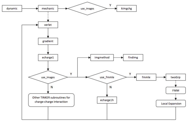
As pointed out earlier, the ICSM has been integrated into the molecular dynamics portion of the TINKER package to provide a new way to calculate charge-charge electrostatic interactions. How the ICSM is integrated into TINKER is schematically shown in Fig. 2. As described in detail later, the changes needed to the original TINKER source files are minimal. As a matter of fact, the only major change required is to add in the TINKER subroutine echarge1() a call to the ICSM subroutine imgmethod() and another subsequent call to another ICSM subroutine fmmle(). In this sense, the (modified) TINKER subroutine echarge1() could be regarded as the interface between TINKER and the ICSM. In simulations the call for the ICSM is controlled by the keyword imgmethod in the keyword parameter file, and when the keyword imgmethod is present, the logical variable use images is set to .true. in the (modified) TINKER subroutine prmkey(). It should also be mentioned that a new subroutine echarge1h() is added into echarge1.f for calculating electrostatic interactions by the ICSM without using the FMM. And whether or not to use the FMM in the ICSM is determined by another keyword fmmle in the keyword parameter file, and when the keyword fmmle is present, the logical variable use fmmle is set to .true. accordingly.
Fig. 2.
The schematic illustration of the flowchart of the integration of the ICSM into TINKER.
If the keyword imgmethod is present in the keyword parameter file, the ICSM subroutine kimgchg() is first called by the TINKER subroutine mechanic() to initialize or calculate the variables unique to the ICSM, including the Gauss-Radau quadrature points and weights . Then later the ICSM subroutine imgmethod() is called by the TINKER sub-routine echarge1() to (1) locate periodic images in Region III for those solvent particles in Region II of the simulation box Λ, and (2) find image charges of reaction field for all charges inside the spherical cavity Γ. To this end, the atoms in each molecule inside the simulation box Λ are first checked to see if they are inside Region II. If any part of the molecule is inside Region II, the positions of the periodic images of its atoms are calculated and stored in an image-position array, and the charges of these periodic images are stored in an image-charge array accordingly. Remember that only those periodic images that are indeed located inside the buffer zone are kept and contribute to the reaction field corrections. Once all periodic images are found and stored, the locations as well as the magnitudes of image charges are then calculated using Eq. (4) and stored in corresponding arrays for all real and periodic image charges inside the spherical cavity Γ if Ni ≥ 1. Lastly, the electrostatic forces exerted on all real “target” charges inside the simulation box Λ by all “source” charges, including real charges inside Λ, periodic images in Region III, and image charges of reaction fields outside the spherical cavity Γ, are calculated either pairwisely by calling echarge1h() or by the FMM, depending on whether the keyword fmmle is present in the keyword parameter file. Once this last step is done, the electrostatic forces are then added to the values in TINKER’s force arrays and control is returned to TINKER by the ICSM.
If the keyword fmmle is present in the keyword parameter file, the ICSM subroutine fmmle() is called to calculate the above electrostatic forces by the FMM together with the local expansion procedure described in Section 2. First, all “source” charges are split into two groups based on where they are located by calling the ICSM subroutine twoGrp(). If a charge is located inside the cut-off reference sphere Sr, it is put in the “inside” group; otherwise it is put in the “outside” group. Next, the electrostatic forces exerted on all “targets” inside the simulation box Λ by those “source” charges from the “inside” group are evaluated using the FMM, while the forces exerted on the same “targets” by those “source” charges from the “outside” group are calculated using the local expansion (LE). The forces calculated by the FMM and the local expansion are then added together to finally obtain the total electrostatic forces.
3.2 Installation and overview of individual components
To install the integrated TINKER and ICSM package, one needs first to download the TINKER package from the website http://dasher.wustl.edu/TINKER/, and extract the package to the directory that it will be run from. Note that all source files of the TINKER package are located in the source subdirectory. Then, one needs to download the ICSM package from http://www.math.uncc.edu/~wcai/TINKER-icsm. After extraction of the zip file, the ICSM package contains several modified TINKER files and four top-level modules: ICSM, FMM, LE, and EXAMPLES. Next, one needs to copy all of the files and directories of the ICSM package into TINKER’s source subdirectory. Finally, one needs to modify the make file makefile, located in the source directory, to include the run path and computer specifications for the system the integrated package will be compiled on. For detailed information on the installation see the manual included with TINKER [10].
As mentioned, several TINKER files were edited. More specifically, the following TINKER files have been modified in order to integrate the ICSM into TINKER.
echarge1.f - added the call to the ICSM to calculate electrostatic interactions.
prmkey.f - added a few lines required to use the ICSM.
mechanic.f - added lines to call the initializing routine for the ICSM.
sizes.i - added parameter settings required to use the ICSM.
potent.i - added parameter settings required to use the ICSM. (f) Makefile
The subdirectory ICSM contains the following subroutines for the ICSM.
imgmethod.f - the main call for the ICSM.
fmmle.f - use the FMM and the local expansion to calculate the electrostatic force field in the TO box.
kimgchg.f - initialize variables singular to the ICSM. Also calculate the Gauss-Radau quadrature points and weights .
findimg.f - find image charges for charges inside the spherical cavity Γ as shown in Fig. 1.
imgchgs.i - define variables unique to the ICSM
The subdirectory LE contains the files needed for the special local expansion as pointed out in Section 2. On the other hand, the subdirectory FMM contains the FMM-Yukawa source files downloaded from the website http://www.fastmultipole.org/ but with a few files being modified and renamed. In particular, the new file ICSMFMMdriver.f serves as the interface between the ICSM and the FMM. The new file ICSMFMMadaplap.f, modified based on and renamed from fmmadaplap.f, now calculates both electrostatic potentials and forces. In addition, parm-alap.h is renamed as fmm.i for naming consistency.
The last subdirectory EXAMPLES contains an input file water 30A.xyz and a keyword parameter file water 30A.key needed for a test simulation of liquid water for a 30 Å simulation box, using the integrated TINKER and ICSM package with one image charge and a buffer layer of thickness τ = 6 Å.
3.3 Execution and modification of the keyword parameter file
After successful compilation of the package, the command line to run TINKER with the integrated ICSM module is the same as that to start TINKER; see Section 4.1 for a specific example. In order to invoke the ICSM to calculate electrostatic interactions, however, the following two keyword lines need be added to the keyword parameter file:
imgmethod  <buffer size tau>  <number of images N_i>
fmmle      <LE order p>     <factor kappa>
For both keywords imgmethod and fmmle, the meaning of their two values are self-explanatory. Indeed, <buffer size tau> specifies the thickness τ of the buffer zone in Angstrom as shown in Fig. 1, <number of images N i> specifies the number of images Ni used to calculate image charges as given by Eq. (3), <LE order p> specifies the local expansion order p as defined in Eq. (13) of Ref. [1], and finally <factor kappa> specifies the parameter κ used to define the reference sphere for the local expansion as shown in Fig. 5 of Ref. [1], respectively.
For instance, the following two keyword lines in the keyword parameter file
imgmethod   6.0   1
fmmle       10   2.0
would make TINKER call the ICSM module to calculate the electrostatic force field in the main simulation cell with these model parameters: τ = 6 Å, Ni = 1, p = 10, and κ = 2.0, respectively.
4 Test simulations and discussions
In order to validate the ICSM integrated into the TINKER molecular modeling package, we apply TINKER 6.0 with the integrated ICSM to liquid water simulation. We run the same benchmarks on the physical properties of bulk water as in our previous paper [1], including the density, the structural oxygen-oxygen radial distribution function, the self-diffusion coefficient, and the dielectric constant. The results are compared to the PME calculations included in the TINKER package and to the published results obtained by the original in-house ICSM software [1]. That is, unless otherwise specified, for each test, three different kinds of simulations are performed: one by TINKER with the built-in PME using neighbor lists, one by TINKER with the integrated ICSM using one image charge (Ni = 1), and one by the original in-house ICSM program used in Ref. [1] also with one image charge. And for convenience, the corresponding results are marked as “TINKER - PME”, “TINKER -ICSM”, and “ICSM”, respectively. The machine on which we compile the integrated package and perform the test simulations is a Red Hat Enterprise Linux 6 server with dual Xeon E5450 processors and 32 Gigabytes of memory, and the compiler is gcc-4.4.5-6.
4.1 Simulation details
We use the TIP3P [23] all-atom model to characterize properties of bulk water. The implementation details of the in-house ICSM program can be found in Ref. [1]. In all three approaches employed, positions and velocities of particles are calculated using the velocity Verlet algorithm, coupled with the Nosé-Hoover thermostat. For each test, three different simulation boxes with L = 30, 45, and 60 Å are considered, the number of atoms contained in these boxes being 1224, 4224, and 10275, respectively. The corresponding initial coordinates are the identical input files used in Ref. [1], which were generated from an equilibrium 200 ps simulation in NPT ensemble, performed by the GROMACS program package. Since it was found in Ref. [1] that the thickness of the buffer zone had to be at least 6 Å in order to yield the uniform density of the simulated bulk water inside the TO, we use a six Angstrom buffer zone for all tests reported in this work, namely, τ = 6 Å. In addition, each dynamics simulation was 1.1 ns long with the first 0.1 ns used for equilibration time, while the integration time step was set to 2 fs. The simulations were performed under constant temperature conditions at T = 300 K. The trajectories were recorded at every 0.2 ps for subsequent analysis whose details can be found in Ref. [1] too. In all simulations, for the FMM-Yukawa software, the maximum number of particles in a leaf box of the adaptive oct-tree structure was set to 80 (nbox=80). The number of terms in the multipole and local expansions and that in the plane wave expansion were both set to 9 for three-digit accuracy (nterms=9, nlambs=9).
For the proposed TIP3P liquid water tests, a typical command line for running TINKER with the integrated ICSM would be:
Dynamic water_30A.xyz 550000 2.0 0.2 2 300
where Dynamic is the TINKER executable, water 30A.xyz represents the input file for the 30 Å simulation box, 550,000 is the number of total time steps, 2.0 is the time step size in femtoseconds, 0.2 indicates the trajectory is recorded after every 0.2 picoseconds, 2 indicates to use the NVT ensemble, and 300 is the temperature, respectively. And a corresponding typical keyword parameter file water 30A.key could be:
parameters           none
octahedron
randomseed          123456789
thermostat           Nose-Hoover
vdwtype             LENNARD-JONES
vdw-cutoff           10.0
radiusrule            geometric
radiustype            SIGMA
radiussize            DIAMETER
epsilonrule           geometric
dielectric            80.0
a-axis               30.0000
b-axis               30.0000
c-axis               30.0000
integrate             verlet
rattle                water
tau-temperature       0.1
# ICSM Parameters
imgmethod           6.0     1
fmmle               10     2.0
# Water Parameters
atom        1   O   “O Water (TIP3P)”      8  15.9994  2
atom        2   H   “H Water (TIP3P)”      1   1.008   1
vdw         1         3.15061     0.152072595
vdw         2              0.000     0.000
bond        1   2           529.6     0.9572
angle        2   1  2        34.05     104.52
ureybrad     2   1  2       38.25     1.5139
charge       1       −0.834
charge       2              0.417
4.2 Results and discussions
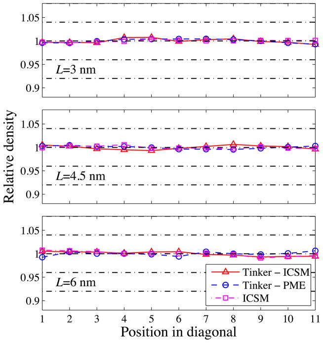
To validate TINKER with the integrated ICSM, as in Ref. [1], first we examine the local particle density across the simulation box as a measure of the homogeneity of the simulated bulk water. More specifically, we compute the relative density of oxygen atoms along the diagonal of the TO simulation box, and the results are plotted in Fig. 3. As can be seen, for all three box sizes, the relative densities obtained by the three different approaches are in good agreement with each other, all showing a uniform density distribution with some statistical variations which are quantitatively summarized in Table 1.
Fig. 3.
Computed relative density along the diagonal of the TO simulation box for three different box sizes with L = 30, 45, and 60 Å, respectively.
Table 1.
Standard deviations of relative densities along the diagonal of TO simulation boxes.
| TINKER - ICSM | TINKER - PME | ICSM | |
|---|---|---|---|
| 30 Å | 0.004 | 0.004 | 0.002 |
| 45 Å | 0.004 | 0.003 | 0.003 |
| 60 Å | 0.003 | 0.004 | 0.004 |
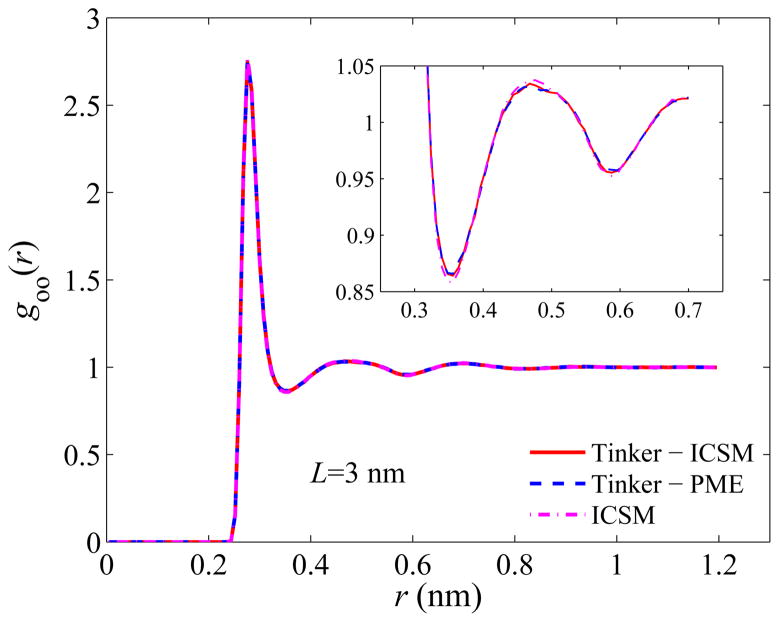
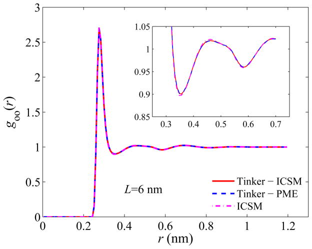
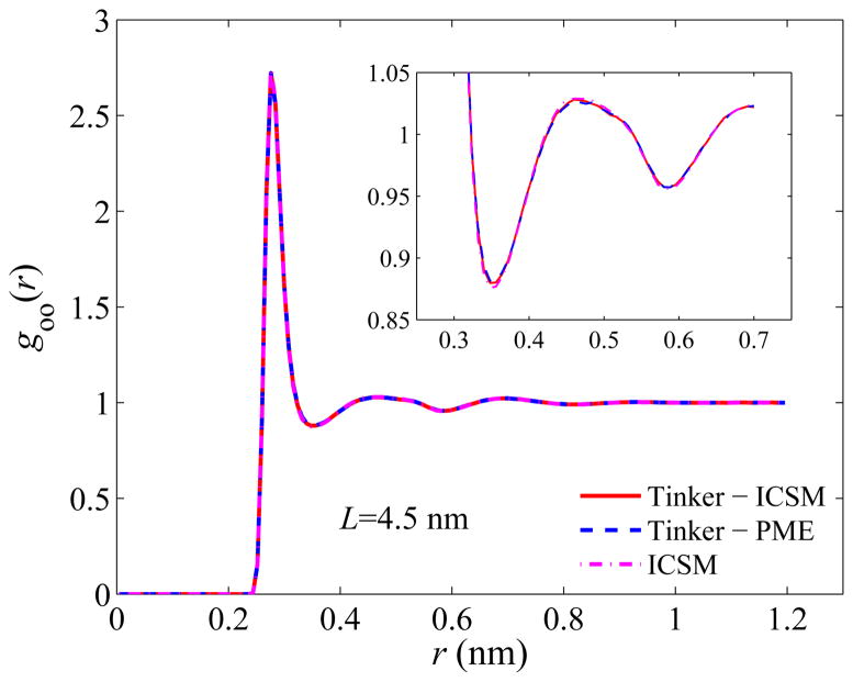
Next, we examine the structure of the simulated bulk water. Again, we evaluate the structure using goo(r), the oxygen-oxygen radial distribution function (RDF), over the entire simulation box, and the results are plotted in Figs. 4–6. Recall that the most important features of goo(r) are the locations as well as the magnitudes of the first three density peaks and the first two density minima. As can be seen, for all three box sizes, the RDFs obtained by the three different approaches are in excellent agreement with each other, and a closer look at goo(r) using a higher resolution, shown in the insets of Figs. 4–6, reveals some noticeable but yet slight difference only for the first two maxima and the first minimum. For example, the first density maxima all lie at 2.76 Å for all box sizes for all three models, while their values are shown in Table 2. On the other hand, the first density minima are all located around 3.56 Å and their values are given in Table 3.
Fig. 4.
Computed oxygen-oxygen RDFs for a 30 Å TO simulation box. The inset shows a closeup of the first two density minima.
Fig. 6.
Same as Fig. 4 but for a 60 Å simulation box.
Table 2.
Magnitudes of the first density maxima in the computed RDFs.
| TINKER - ICSM | TINKER - PME | ICSM | |
|---|---|---|---|
| 30 Å | 2.74 | 2.75 | 2.77 |
| 45 Å | 2.72 | 2.72 | 2.74 |
| 60 Å | 2.70 | 2.70 | 2.71 |
Table 3.
Magnitudes of the first density minima in the computed RDFs.
| TINKER - ICSM | TINKER - PME | ICSM | |
|---|---|---|---|
| 30 Å | 0.864 | 0.866 | 0.858 |
| 45 Å | 0.880 | 0.881 | 0.876 |
| 60 Å | 0.900 | 0.901 | 0.897 |
Then, we examine the dynamical properties of the simulated water. More precisely, we once again choose to evaluate the self-diffusion coefficient D, a transport coefficient characterizing how quickly equilibrium is established in particle density following a small perturbation. The self-diffusion coefficients obtained by the three different approaches are recorded in Table 4. As it shows, the self-diffusion coefficient obtained by TINKER with the integrated ICSM is consistent, within statistical errors, with both the values obtained by the PME included in TINKER and the original findings from Ref. [1] which were obtained using the original in-house ICSM software. Also note that the standard deviation decreases as the box size increases.
Table 4.
Computed self-diffusion coefficients D with standard deviations (unit: 10−9 m2s−1).
| TINKER - ICSM | TINKER - PME | ICSM | |
|---|---|---|---|
| 30 Å | 6.15(±0.12) | 6.16(±0.12) | 6.28(±0.03) |
| 45 Å | 6.16(±0.04) | 6.24(±0.07) | 6.19(±0.02) |
| 60 Å | 6.03(±0.03) | 6.06(±0.05) | 6.02(±0.01) |
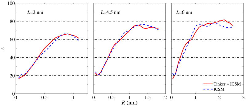
Last, to validate TINKER with the integrated ICSM, we examine the dielectric properties of the simulated bulk water by computing its dielectric constant ε. In particular, Formula (A3) of Ref. [1] is used to calculate the dielectric constant ε (R) as a function of the sample radius R which can vary between 0 and for a TO simulation box with size L; the readers are referred to Ref. [1] for the meaning of this radius R and the detailed derivation of this formula. As stated in Ref. [1], since ε is a macroscopic property of a liquid material, it is physically meaningful only for a relatively large volume of the material objects. Once a crossover from a finite-size to macroscopic dimensions is achieved, the dielectric constant should be largely independent of the geometry of the investigated object. In the case of ε(R), a plateau should be expected in its graph starting at some radius. Figure 7 shows the computed dielectric constant ε(R) obtained, respectively, by TINKER with the integrated ICSM and the original in-house ICSM software. Again, good agreement between these two simulation results can be observed.
Fig. 7.
Dielectric constant ε(R) as a function of the spherical sample radius R computed using Formula (A3) of Ref. [1] for three different TO simulation boxes with L = 30, 45, and 60 Å, respectively. For sufficiently large R, ε(R) is seen to level off, and the plateau value in ε(R) is identified as the static dielectric constant of the material. Note that, as in Ref. [1], this static dielectric constant is seen to grow from ~65 at L = 30 Å to ~80 at L = 60 Å.
4.3 Timing analysis
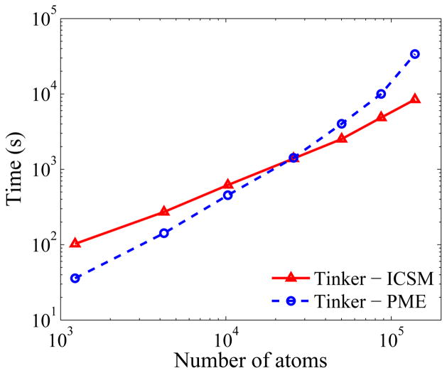
Finally, to test the performance of the ICSM integrated into TINKER, we compare the timing required to run TINKER with the integrated ICSM using the FMM against the timing required to run TINKER with the built-in PME. To this end, in addition to the three simulation boxes used above, larger simulation boxes with L = 80 Å, 100 Å, 120 Å, and 140 Å are also considered. For each case, the corresponding simulation is run for 1000 time steps and the time required to run, calculated using the TIME function built into the UNIX, is plotted in Fig. 8 as a function of the number of atoms in the system. As can be seen, for relatively small systems, TINKER with the built-in PME runs faster than TINKER with the integrated ICSM, while for sufficiently large systems the latter clearly outperforms the former. The break-even point is at around 30,000 atoms.
Fig. 8.
Results of timing tests using TINKER with the integrated ICSM and TINKER with the built-in PME, respectively. Test runs were carried out for 1000 time steps and the time used was calculated using the TIME function built into the UNIX. TINKER with the integrated ICSM starts to outperform TINKER with the built-in PME at approximately 30,000 atoms.
5 Conclusions
In all tests using TINKER with the integrated ICSM module, the physical properties of the simulated water were found to be consistent with those reported in Ref. [1] which were obtained by the original in-house ICSM code. In that work, it was found that the ICSM could not compete with the PME in speed, although the theoretical scaling (O(N) versus O(N log N)) would suggest that the ICSM should be faster for very large systems. However, that comparison was made for relatively small systems and across multiple simulation packages. In this work, we showed that within one package, the ICSM outperforms the PME for large systems, as implied by the asymptotic complexity of these two methods. With the new implementation of the FMM, and with respect to the PME calculations available in TINKER, the crossover point has been substantially reduced. In particular, for the implementation presented here, the ICSM module in the TINKER will run faster for systems containing a large number of atoms of about 30,000 charges, or a simulation box of 80 Å across. We note that boxes of this size have become common in computational studies of biological molecules [24]. Moreover, continuing development of the FMM may further improve the ICSM’s performance in the future.
Currently we are testing the integrated TINKER package on a system containing an alanine dipeptide as this peptide has been widely studied in the literature and its properties are readily available for comparison purposes. We are also testing it for systems containing charged solvents. Any significant findings will be reported in future publications.
Finally, it should, however, be mentioned that in the current implementation of the ICSM in TINKER, only the echarge1() subroutine is modified to add the ICSM method. Consequently, the current usage of the ICSM in TINKER is limited to only the long-range charge-charge electrostatic potential and force calculations. While the TINKER subroutines echarge() and echarge3() could be modified similarly to include the ICSM method for the calculation of only the electrostatic potential energy, at this point it is not possible to integrate the ICSM into the TINKER subroutine echarge2() to do Hessian calculations because the current FMM package does not support the calculation of the second derivative of the charge-charge electrostatic interaction energy.
Fig. 5.
Same as Fig. 4 but for a 45 Å simulation box.
Acknowledgments
The support of the National Institutes of Health through Grant No. 1R01GM083600-04 is gratefully acknowledged.
Footnotes
Preprint submitted to Elsevier
Publisher's Disclaimer: This is a PDF file of an unedited manuscript that has been accepted for publication. As a service to our customers we are providing this early version of the manuscript. The manuscript will undergo copyediting, typesetting, and review of the resulting proof before it is published in its final citable form. Please note that during the production process errors may be discovered which could affect the content, and all legal disclaimers that apply to the journal pertain.
References
- 1.Lin Y, Baumketner A, Deng S, Xu Z, Jacobs D, Cai W. An image-based reaction field method for electrostatic interactions in molecular dynamics simulations of aqueous solutions. J Chem Phys. 2009;131:154103. doi: 10.1063/1.3245232. [DOI] [PMC free article] [PubMed] [Google Scholar]
- 2.Cai W, Deng S, Jacobs D. Extending the fast multipole method to charges inside or outside a dielectric sphere. J Comput Phys. 2007;223:846–864. doi: 10.1016/j.jcp.2007.09.001. [DOI] [PMC free article] [PubMed] [Google Scholar]
- 3.Deng S, Cai W. Discrete image approximations of ionic solvent induced reaction field to charges. Commun Comput Phys. 2007;2:1007–1026. [Google Scholar]
- 4.Deng S, Cai W. Extending the fast multipole method for charges inside a dielectric sphere immersed in an ionic solvent: High-order image approximations for reaction fields. J Comput Phys. 2007;227:1246–1266. doi: 10.1016/j.jcp.2007.09.001. [DOI] [PMC free article] [PubMed] [Google Scholar]
- 5.Greengard L, Rokhlin V. A fast algorithm for particle simulations. J Comput Phys. 1987;73:325–348. [Google Scholar]
- 6.Greengard L. The Rapid Evaluation of Potential Fields in Particle Systems. MIT Press; Cambridge, MA: 1987. [Google Scholar]
- 7.Huang J, Jia J, Zhang B. FMM-Yukawa: An adaptive fast multipole method for screened Coulomb interactions. Comput Phys Commun. 2009;180:2331–2338. [Google Scholar]
- 8.Zhang B, Huang J, Pitsianis NP, Sun X. Revision of FMM-Yukawa: An adaptive fast multipole method for screened Coulomb interactions. Comput Phys Commun. 2010;181:2206–2207. [Google Scholar]
- 9.Lin Y, Baumketner A, Song S, Deng S, Jacobs D, Cai W. Ionic solvation studied by image-charge reaction field method. J Chem Phys. 2011;134:044105. doi: 10.1063/1.3530094. [DOI] [PMC free article] [PubMed] [Google Scholar]
- 10.Ponder JW. TINKER - Software Tools for Molecular Design. 2004 doi: 10.1021/acs.jctc.8b00529. http://dasher.wustl.edu/ffe/downloads/guide.pdf. [DOI] [PMC free article] [PubMed]
- 11.Ren P, Ponder JW. Polarizable atomic multipole water model for molecular mechanics simulation. J Phys Chem B. 2003;107:5933–5947. [Google Scholar]
- 12.Ren P, Ponder JW. Consistent treatment of inter- and intramolecular polarization in molecular mechanics calculations. J Comput Chem. 2002;23:1497–1506. doi: 10.1002/jcc.10127. [DOI] [PubMed] [Google Scholar]
- 13.Pappu RV, Hart RK, Ponder JW. Analysis and application of potential energy smoothing and search methods for global optimization. J Phys Chem B. 1998;102:9725–9742. [Google Scholar]
- 14.Hodsdon ME, Ponder JW, Cistola DP. The NMR solution structure of intestinal fatty acid-binding protein complexed with palmitate: Application of a novel distance geometry algorithm. J Mol Biol. 1996;264:585–602. doi: 10.1006/jmbi.1996.0663. [DOI] [PubMed] [Google Scholar]
- 15.Kundrot CE, Ponder JW, Richards FM. Algorithms for calculating excluded volume and its derivatives as a function of molecular conformation and their use in energy minimization. J Comput Chem. 1991;12:402–409. [Google Scholar]
- 16.Ponder JW, Richards FM. An efficient newton-like method for molecular mechanics energy minimization of large molecules. J Comput Chem. 1987;8:1016–1024. [Google Scholar]
- 17.Friedman HL. Image approximation to the reaction field. Mol Phys. 1975;29:1533–1543. [Google Scholar]
- 18.Gautschi W. Algorithm 726; ORTHPOL-a package of routines for generating orthogonal polynomials and Gauss-type quadrature rules. ACM T Math Software. 1994;20:21–62. [Google Scholar]
- 19.Greengard L, Roklin V. A new version of the fast multipole method for the Laplace equation in three dimensions. Acta Numer. 1997;6:229–269. [Google Scholar]
- 20.Greengard L, Huang J. A new version of the fast multipole method for screened Coulomb interactions in three dimensions. J Comput Phys. 2002;180:6428. [Google Scholar]
- 21.Cheng H, Greengard L, Roklin V. A fast adaptive multipole algorithm in three dimensions. J Comput Phys. 1999;155:468–498. [Google Scholar]
- 22.Ying L, Biros G, Zorin D. A kernel-independent adaptive fast multipole method in two and three dimensions. J Comput Phys. 2004;196:591–626. [Google Scholar]
- 23.Jorgensen WL, Chandrasekhar J, Madura JD, Impey RW, Klein ML. Comparison of simple potential functions for simulating liquid water. J Chem Phys. 1983;79:926–935. [Google Scholar]
- 24.van Gunsteren WF, Bakowise D, Baron R, et al. Biomolecular modeling: Goals, problems, perspectives. Angew Chem Int Ed. 2006;45:4064–4092. doi: 10.1002/anie.200502655. [DOI] [PubMed] [Google Scholar]


