Abstract
Anaerobic digestion (AD) is a bioprocess that is commonly used to convert complex organic wastes into a useful biogas with methane as the energy carrier 1-3. Increasingly, AD is being used in industrial, agricultural, and municipal waste(water) treatment applications 4,5. The use of AD technology allows plant operators to reduce waste disposal costs and offset energy utility expenses. In addition to treating organic wastes, energy crops are being converted into the energy carrier methane 6,7. As the application of AD technology broadens for the treatment of new substrates and co-substrate mixtures 8, so does the demand for a reliable testing methodology at the pilot- and laboratory-scale.
Anaerobic digestion systems have a variety of configurations, including the continuously stirred tank reactor (CSTR), plug flow (PF), and anaerobic sequencing batch reactor (ASBR) configurations 9. The CSTR is frequently used in research due to its simplicity in design and operation, but also for its advantages in experimentation. Compared to other configurations, the CSTR provides greater uniformity of system parameters, such as temperature, mixing, chemical concentration, and substrate concentration. Ultimately, when designing a full-scale reactor, the optimum reactor configuration will depend on the character of a given substrate among many other nontechnical considerations. However, all configurations share fundamental design features and operating parameters that render the CSTR appropriate for most preliminary assessments. If researchers and engineers use an influent stream with relatively high concentrations of solids, then lab-scale bioreactor configurations cannot be fed continuously due to plugging problems of lab-scale pumps with solids or settling of solids in tubing. For that scenario with continuous mixing requirements, lab-scale bioreactors are fed periodically and we refer to such configurations as continuously stirred anaerobic digesters (CSADs).
This article presents a general methodology for constructing, inoculating, operating, and monitoring a CSAD system for the purpose of testing the suitability of a given organic substrate for long-term anaerobic digestion. The construction section of this article will cover building the lab-scale reactor system. The inoculation section will explain how to create an anaerobic environment suitable for seeding with an active methanogenic inoculum. The operating section will cover operation, maintenance, and troubleshooting. The monitoring section will introduce testing protocols using standard analyses. The use of these measures is necessary for reliable experimental assessments of substrate suitability for AD. This protocol should provide greater protection against a common mistake made in AD studies, which is to conclude that reactor failure was caused by the substrate in use, when really it was improper user operation 10.
Keywords: Bioengineering, Issue 65, Environmental Engineering, Chemistry, Anaerobic Digestion, Bioenergy, Biogas, Methane, Organic Waste, Methanogenesis, Energy Crops
Protocol
1. Digester Construction
Select a digester vessel that contains all the features shown in Fig. 1 (a cone is not necessary), and your desired working volume (typically between 1-10 L). If your digester vessel is not equipped with a heated-water jacket, place the digester in some other temperature-controlled environment, such as a heated water bath or incubation chamber.
Secure the vessel in a vertical position in an area with sufficient horizontal bench space for placement of remaining components (Table 2).
Construct the vessel lid according to Fig. 2. The ports of the influent and effluent tubes should be wide enough to prevent clogging. The tubes inside the bioreactor should be of sufficient length to stay submerged in the digester medium during decanting, while extending out from the top of the lid to allow attachment of tubing. The impeller sheathing should extend as far as possible into the digester medium (the submerged tubing and sheathing prevent headspace biogas from escaping the bioreactor).
Apply silicone-based vacuum grease to the contact surface of the lid and clamp it to the digester vessel top.
Secure the variable speed mixer parallel to the digester's vertical axis using a ring-stand and clamps, then affix impeller shaft. Because of mixer motor vibrations and movement it is important to use an independent and free moving stand.
Connect a section of flexible tubing to both the influent and effluent tubes and then connect another section of tubing to the gas port to be used as the gas line.
- Connect the biogas line to each of the various components, which can be placed above the digester on shelving. The components should be connected in this order: sampling port, foam trap, H2S scrubber, gas reservoir, bubbler, gas meter, and ventilation line (Fig. 3). To facilitate isolation or removal of individual components for troubleshooting or cleaning purposes, consider adding valves and connecter fittings between components. Make sure that the gas outlet is properly ventilated to the outside or a chemical hood because biogas is explosive.
- The gas sampling port should be positioned near the reactor headspace.
- The foam trap can be constructed using a simple flask or bottle, and should be at least 25% of the reactor volume. It should contain two ports, one for the biogas inlet line and the other for the biogas outlet line. These ports can be made by drilling two holes in a rubber stopper through which rigid tubing is inserted. The biogas inlet tube should extend to a greater depth than the biogas outlet tube (Fig. 4). Foam trapping is necessary to protect the gas handling system from possible digester foam.
- The H2S scrubber consists of a long glass tube, with an inner diameter greater than 2 cm, filled with steel wool with a biogas inlet and outlet port on either end. The steel wool should be packed well to provide enough surface area for stripping, but not so tightly that biogas flow is blocked. Scrubbing is necessary to protect metal components in the gas meter from corrosive chemicals.
- The gas reservoir can be made out of any collapsible, air-tight material, such as a gas bag, or even a children's play ball, with a volume exceeding twice the targeted feed volume. This is necessary to prevent a pressure drop during decanting effluent and possible air suction into the headspace.
If the system will be temperature controlled by a circulating water heater, connect the heater to the heating jacket using flexible tubing. Place the unit above the liquid level of the heating jacket. Set the heater to the appropriate temperature for mesophilic or thermophilic digestion (Table 1).
Perform a leak test of the system by detecting leaks with soapy water. Start by filling the digester tank with water, then slightly pressurize the influent line with a gas to a pressure less than 5 psi. First, clamp the biogas line and effluent lines to check for leaks around the reactor lid, and then remove the biogas line clamp to test for leaks for the entire gas handling system. Note that over-pressurization of the influent line will force water out through the impeller sheathing tube.
Turn on the impeller and heating element and let run overnight to ensure that the mixer and heater can sustain continuous operation. The rotational speed of the impeller should be fast enough to ensure complete mixing of the reactor media. Common mixer problems include misalignment, excessive friction of the shaft, and inadequate securing of the motor to the ring-stand.
2. Digester Inoculation and Conditioning using an Active Methanogenic Biomass
Store the active methanogenic biomass (inoculum) in a closed container in a refrigerator at 4 °C while preparing the digesters. Ideally, the inoculum should be stored for as little time as possible and there should be enough to completely fill the entire volume of the digester. However, certain anaerobic biomass (such as granular biomass) can be stored for very long periods. Dilute the inoculum with water that was flushed with an anaerobic gas to the appropriate volume if necessary.
Flush the empty digester system with anaerobic gas for several minutes by connecting it to the feeding tube, clamping the effluent line, and taping the space between the mixer axle and sheath to prevent excessive loss of anaerobic gas.
During the flushing period, make sure to flush-out the gas reservoir.
After flushing is complete, connect a funnel to the feeding tube and add the inoculum making sure to mix the inoculum periodically to ensure uniformity.
Reconnect the anaerobic gas to the feeding tube, turn-on the mixer, and flush the digester liquor for at least 15 min. Then disconnect the gas, clamp the feed tube and unclamp the gas reservoir. This digester is now in operation.
Allow the digester to operate for a couple of days before commencing feeding and monitor the production of biogas. During this time, perform total solids and volatile solids concentration analysis for the inoculum (Table 1). If the solids concentration is considerably greater than that of the target mixed liquor concentration, remove and dilute digester contents accordingly before commencing feeding. This is done to prevent excessive washout of biomass during the operating period that may increase the Food to Microorganism (F/M) ratio too sharply throughout the startup period.
Determine the organic biodegradable fraction of the substrate by measuring either the total and volatile solids concentration, biological or chemical oxygen demand, or total organic carbon of the substrate. Use this value to calculate a conservative initial organic loading rate (OLR).
The operator should gradually increase the OLR until a target value is reached (start-up period). One approach during the start-up period is to fix the organic strength of the feed, and then reduce the hydraulic retention time (HRT) incrementally until the target OLR is achieved (a process that may take several months to a year depending on the quality of the inoculum and the substrate used). Increasing the OLR too quickly will lead to excessive concentrations of volatile fatty acids (>2,000 mg/L as acetate) as shown in Fig. 5. The operator should reduce the OLR if volatile fatty acid concentrations increase to suboptimum levels (Table 1). If the volatile fatty acid concentrations are too high, the contents of the bioreactor may need to be diluted with water.
Allow the digester a period of three HRTs at the target OLR before experimentation to establish a stable base-line condition.
3. Digester Operation
Effluent decanting always precedes substrate addition to the digester, so immediately before decanting, prepare the feed mixture and store at 4 °C until it is time to feed.
Decant effluent from the digester by connecting the effluent tubing to a pump (side-arm flask under vacuum is one possibility of decanting) and remove an equal volume compared to the feed volume. Store the effluent at 4 °C for later analysis. Note that many of the analyses are time sensitive. For example, the pH should be measured immediately because CO2 escapes from the solution, increasing the pH.
Remove the feed mixture from the refrigerator. Connect a funnel to the feed tube and pour in the feed (substrate) making sure to mix periodically to ensure that the solids get carried in with the bulk fluid.
Perform troubleshooting steps outlined in Table 3, if necessary.
4. System Monitoring
Check the digester system and its components frequently during operation. Particular attention should be paid to the mixing and heating systems. Insufficient mixing will manifest in an abrupt decrease in effluent solids concentration (Fig. 6). Periodically check that the oil or water in the gas meters is at the appropriate level and replace the steel wool in the H2S trap as needed. Note that the steel wool will become black and glossy as it reacts with H2S to form iron sulfide.
- Perform these analyses on digester effluent for diagnosis of system performance and stability. The values should consistently fall within the specified optimum range indicated in Table 1.
- Measure the biogas production rate and pH every feeding cycle.
- Measure the volatile fatty acid concentration, alkalinity, and biogas content multiple times a week. Note: The biogas content should be measured at the same time relative to the feeding cycle since its composition will change over the course of the cycle. Ideally, the biogas should be sampled at the end of a feeding cycle, just prior to feeding.
- Measure the biological or chemical oxygen demand and total and volatile solids once a week or more often to obtain at least three data points for each experimental condition at pseudo-steady state conditions.
5. Representative Results
Successful inoculation of the digester is marked by the production of biogas within several days. The methane to carbon dioxide ratio of the biogas will increase during the acclimatization period as more methanogenic biomass is recruited. The slow growth of methanogens compared to acidogens makes long acclimatization periods and gradual operational changes necessary. In Fig. 5, we demonstrate the dynamic response of a digester when a high organic loading rate (OLR) is introduced too early in the start-up phase. In this example, there was insufficient methanogenic biomass to remove (i.e., utilize) the volatile fatty acids (VFAs) evolved from the substrate degradation step, acidogenesis. This led to an accumulation of VFAs, and subsequently, a reduction in the pH. To rectify this situation, the OLR was reduced to limit the production of VFAs by acidogens and to allow greater methanogen recruitment before returning to the higher OLR. The digesters then exhibited stable digestion for three hydraulic retention periods.
Stable digestion or pseudo-steady-state conditions can be assumed when the measured parameters, such as the biogas production rates, total VFA concentrations, volatile solids concentrations, and pH levels, are consistently maintained within 10% of their average values, for a minimum time period of one HRT. The significance of this allotment is revealed in Fig. 6, which shows the prolonged response of the CSTR system to a perturbation caused by insufficient mixing. The lack of proper mixing allowed the solids to settle in the reactor, which meant fewer solids were removed during effluent decanting. Their accumulation resulted in higher effluent solids concentrations after sufficient mixing was restored. It took approximately one HRT (i.e., 25 days) to return the digester to a normal effluent solids concentration.
An anaerobic digester is a biological system; thus it will exhibit some internal variability in performance. This variability must be quantified before the experimenter can discern the specific effects caused by experimental perturbations imposed on the system (the proper use of statistics is required). Three HRT periods are required before an experimental change is made to the reactor system because this is generally considered an adequate period of time to assume stable concentrations of chemical species in the mixed liquor (Fig. 7). By the end of this interval, the experimenter should be able to construct a reliable baseline for each measured parameter. This baseline serves as a basis of comparison for future experimentation.
The general performance of the digester can be assessed by following the monitoring protocol, which requires that various standard analyses be executed routinely. This schedule provides adequate temporal resolution to identify precursors to most system problems and the lee time to prevent them. Furthermore, the results of these diagnostic tests are meant to be used in conjunction with Table 1 to identify suboptimum performance. Table 3 provides solutions to many of the problems typically encountered when setting-up a digester. In the event that a problem cannot be rectified by following the instructions outlined therein, the operator should consult other resources, such as a reference text pertaining to anaerobic biotechnology.
| Operation Parameters | Standard Methods Index | Typical Range | Extreme Range | ||
| Mesophilic | Thermophilic | Mesophilic | Thermophilic | ||
| Temperature | 2550(A) | 32-37 17 °C | 50-60 17 °C | 20-42 17 °C | 45-65 17 °C |
| Organic Loading Rate | NL | 0.8-2.0 17 g VS-L-1-d-1 | 1.5-5.0 17 g VS-L-1-d-1 | 0.4-6.4 17 g VS-L-1-d-1 | 1.0-7.5 17 g VS-L-1-d-1 |
| Hydraulic Retention Time | NL | 15 - 35 Days | < 15 ; > 35 Days | ||
| Carbon: Nitrogen Ratio | NL | 25:1 17 | > 25:1 | ||
| Monitoring Parameters | Standard Methods Index | Optimum Range | Suboptimum Range | ||
| pH | 4500-H+(B) | 6.5 - 8.2 10 | < 6.5 ; > 8.2 | ||
| Alkalinity | 2320(B) | 1300 - 3000 17 mg CaCO3-L-1 | < 1300 mg CaCO3-L-1 | ||
| Volatile Acids | 5560(C) | < 200 10 mg Ac-L-1 | > 200 10 mg Ac-L-1 | ||
| Solids Removal Efficiency | 2540(B,E) | > 50 % | < 50 % | ||
| Biogas Content | 2720(C) | 55-70 CH4; 30-45 CO2 % | < 55 CH4; > 45 CO2 % |
Table 1. General operation selection guide and monitoring parameters for CSTR systems.
| Component | Specifications (Design Considerations) | Comments |
| Temperature-Controlled Circulating Water Heater | Temperature Range: 25-65 °C (Heating Capacity, Max. Pressure Head, Volumetric Flow Rate) | Heated water must be supplied at a sufficiently high flow rate and with sufficient pressure to fully circulate. |
| Sampling Port | NA | Located close to headspace is ideal. |
| Foam Trap | Volume: 25% of Reactor Volume | Simple side-arm flask or glass jars can be used. The unit should be accessible for cleaning. |
| Hydrogen Sulfide Scrubber | (Gas Contact Time) | Glass or plastic tubes should be used (not metal). Sizing length should provide adequate gas contact time. |
| Gas Reservoir | Volume: > 2x Effluent Volume; Material: Semi-Elastic (not Rigid) | The volume should exceed that taken during effluent decanting. The material should allow for shrinking and expansion. |
| Bubbler | NA | The head pressure provided by the water level should be minimized to limit pressure build-up in the gas delivery system. |
| Gas Meter | (Gas Flow Detection Range) | Plastic gas meters are preferred over metal. The gas flow detection range should be accurate at expected biogas production rates. |
Table 2. Auxiliary reactor components with specifications and comments.
| ERROR SYMPTOM | POSSIBLE SOLUTIONS |
| Frequent clogging of feeding or effluent tubes | • Use larger diameter tubing and/or fittings. • Reduce particle substrate size (e.g., using a blender or sieve). • Mix feed more frequently while feeding. • Ensure that digester contents are fully mixed. |
| Excessive foaming | • Reduce the OLR • Reduce the mixing intensity in the digester. • Increase the headspace in the digester by reducing the active digester volume. |
| Inconsistent biogas yield between digester replicates | • Verify that no leaks are present in the gas handling system of either digester. • Check that the gas meter and heating element are functioning properly and are calibrated. • Verify that the feed mixtures are prepared equivalently. |
| Inconsistent or highly variable solids concentration in the effluent between digester replicates (Fig. 6) | • Verify that the digester contents are adequately mixed. • Ensure that the reactor effluent decanting line is equivalent between reactors. |
| Reduced methane content in biogas | • Verify that the pH is within the optimal range for methanogenesis (i.e., 6.5 to 8.2). If not, supplement with acidity or alkalinity as appropriate. • If significant nitrogen is detected in the biogas (i.e., >10%), check for leaks near the sampling port. • Regularize the periodicity of biogas sampling. • Verify that the VFA concentration is within the optimal range. If not, follow troubleshooting steps listed for chronically high volatile fatty acid concentrations. |
| Chronically high volatile fatty acid concentration (Fig. 5) | • Reduce the OLR. • Overcome nutrient or trace metal deficiencies by supplementation. • Verify that the reactor contents are sealed from oxygen intrusion. • Increase feed cycle frequency. • Eliminate hydraulic short circuiting. • Overcome alkalinity deficiency by supplementation. |
Table 3. Troubleshooting protocol for digester operation.
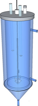 Figure 1. Basic example of reactor design: Body material- Glass; Tubing material- Stainless Steel/Aluminum; Lid material- PVC/Plexiglas.
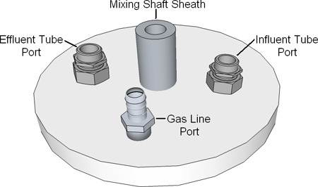 Figure 2. Basic example of reactor lid design: Lid material- PVC/Plexiglas; Fittings material- Stainless Steel/Plastic; Tubing material- Stainless Steel/Aluminum.
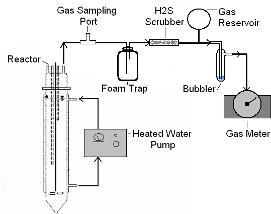 Figure 3. System diagram showing component arrangement.
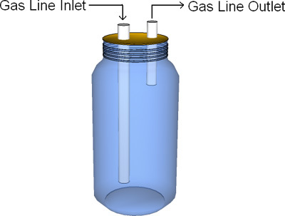 Figure 4. Basic example of foam trap design: Jar material- Plastic/Glass; Tube material- Plastic/Glass.
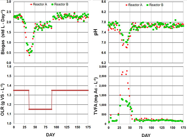 Figure 5. Typical system response to a high organic loading rate (OLR) during reactor start-up. Beginning with an OLR of 1.35 gVS-L-1 caused the accumulation of total volatile fatty acids (TVFA). The acid accumulation caused a decrease in pH followed by a reduction in biogas yield. By lowering the OLR to 1.15 g VS-day-1, both systems were able to recover and establish a sufficient methanogenic biomass concentration to tolerate a 1.35 gVS-L-1 OLR. The difference in pH and TVFA accumulation between reactors exhibits the unique dynamics of mixed communities.
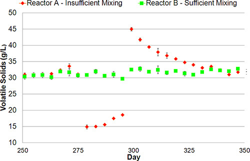 Figure 6.
Typical system response to insufficient mixing (Reactor A) compared to a sufficiently mixed system (Reactor B). During poor mixing, the solids settle to the bottom of the reactor and are not removed during decanting (days 280 - 290). When mixing is returned to sufficient intensity (day 300), the accumulated solids are gradually removed (days 305 - 330), and the system returns to stable solids concentrations.
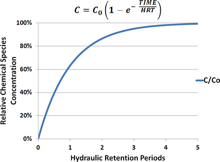 Figure 7.
Theoretical relationship between the concentration of a conservative chemical species and the hydraulic retention period (HRT) in an ideal CSTR system. At three HRTs the actual concentration of a chemical species [C] in the digester is 95% that of the initial concentration present in the feed [C0].
Discussion
The anaerobic digestion system presented in this article provides a general introduction and some basic guidelines for the treatment of most substrates in an experimental context. The wide variety of substrate types, digester configurations, operating parameters, and also the unique ecology of the mixed-microbial community underlying these systems precludes outlining hard quantitative metrics, which can be applied universally. Despite all this variability, all anaerobic digestion systems follow a well-characterized series of biological degradation pathways, which are mediated by physical and chemical processes whose principles are well understood and can be applied to all systems. It is from these fundamental principles, along with well-documented operating observations reported in the literature, that we report these optimum ranges for system parameters and proper system operation methodologies. The cited parameters are interrelated and play important roles in the anaerobic digestion process. A thorough understanding of these interrelationships greatly improves the operator's capacity to recognize and remedy system problems. The text, "Anaerobic Biotechnology: for Industrial Wastewaters" by Speece provides a fairly comprehensive catalog of pertinent operating and monitoring topics in anaerobic digestion for those seeking further insight and explanation10.
Disclosures
No conflicts of interest declared.
Acknowledgments
This research is supported is supported by the USDA through the National Institutes of Food and Agriculture (NIFA), grant number 2007-35504-05381; by grant no. 58872 from NYSERDA and NYC-123444 through the Cornell University Agricultural Experiment Station's federal formula funds from the USDA NIFA.
References
- Dague RR, McKinney RE, Pfeffer JT. Solids retention in anaerobic waste treatment systems. J. Water Pollut. Control Fed. 1970;42:R29–R46. [Google Scholar]
- McCarty PL, Smith DP. Anaerobic wastewater treatment. Environ. Sci. Technol. 1986;20:1200–1206. [Google Scholar]
- Lettinga G. Anaerobic digestion and wastewater treatment systems. Antonie Van Leeuwenhoek. 1995;67:3–28. doi: 10.1007/BF00872193. [DOI] [PubMed] [Google Scholar]
- De Baere L. Anaerobic digestion of solid waste: state-of-the-art. Water Sci. Technol. 2000;41:283–290. [PubMed] [Google Scholar]
- Angenent LT, Karim K, Al-Dahhan MH, Wrenn BA, Domínguez-Espinosa R. Production of bioenergy and biochemicals from industrial and agricultural wastewater. Trends Biotechnol. 2004;22:477–485. doi: 10.1016/j.tibtech.2004.07.001. [DOI] [PubMed] [Google Scholar]
- Jewell WJ, Cummings RJ, Richards BK. Methane fermentation of energy crops - maximum conversion kinetics and in-situ biogas purification. Biomass & Bioenergy. 1993;5:261–278. [Google Scholar]
- Weiland P. Biomass digestion in agriculture: A successful pathway for the energy production and waste treatment in Germany. Eng. Life Sci. 2006;6:302–309. [Google Scholar]
- Zaks DPM. Contribution of anaerobic digesters to emissions mitigation and electricity generation under U.S. climate policy. Environ. Sci. Technol. 2011;45:6735–6742. doi: 10.1021/es104227y. [DOI] [PMC free article] [PubMed] [Google Scholar]
- Tchobanoglous G, Burton FL, Stensel HD. Wastewater Engineering, Treatment and Reuse: Metcalf & Eddy. 4 edn. McGraw Hill; 2003. [Google Scholar]
- Speece RE. Anaerobic Biotechnology for Industrial Wastewaters. Archaea Press; 1996. [DOI] [PubMed] [Google Scholar]
- Kleerebezem R, van Loosdrecht MCM. Mixed culture biotechnology for bioenergy production. Curr. Opin. Biotechnol. 2007;18:207–212. doi: 10.1016/j.copbio.2007.05.001. [DOI] [PubMed] [Google Scholar]
- Angenent LT, Wrenn BA. Chp. 15. In: Wall J, Harwood CS, Demain AL, editors. Bioenergy. ASM Press; 2008. [Google Scholar]
- Werner JJ. Bacterial community structures are unique and resilient in full-scale bioenergy systems. Proc. Natl. Acad. Sci. U.S.A. 2011;108:4158–4163. doi: 10.1073/pnas.1015676108. [DOI] [PMC free article] [PubMed] [Google Scholar]
- Holm-Nielsen JB, Al Seadi T, Oleskowicz-Popiel P. The future of anaerobic digestion and biogas utilization. Bioresour. Technol. 2009;100:5478–5484. doi: 10.1016/j.biortech.2008.12.046. [DOI] [PubMed] [Google Scholar]
- Hoffmann R. Effect of shear on performance and microbial ecology of completely-stirred anaerobic digesters treating animal manure. Biotechnol. Bioeng. 2008;100:38–48. doi: 10.1002/bit.21730. [DOI] [PubMed] [Google Scholar]
- Clesceri LS, Greenberg AE, Eaton AD. Standard Methods for the Examination of Water and Wastewater. 20th edition. Washington, D.C., USA: American Public Health Association; 1998. [Google Scholar]
- Amani T, Nosrati M, Sreekrishnan TR. Anaerobic digestion from the viewpoint of microbiological, chemical, and operational aspects: a review. Environmental Reviews. 2010;18:255–278. [Google Scholar]


