Abstract
As society progresses and resources become scarcer, it is becoming increasingly important to cultivate new technologies that engineer next generation biomaterials with high performance properties. The development of these new structural materials must be rapid, cost-efficient and involve processing methodologies and products that are environmentally friendly and sustainable. Spiders spin a multitude of different fiber types with diverse mechanical properties, offering a rich source of next generation engineering materials for biomimicry that rival the best manmade and natural materials. Since the collection of large quantities of natural spider silk is impractical, synthetic silk production has the ability to provide scientists with access to an unlimited supply of threads. Therefore, if the spinning process can be streamlined and perfected, artificial spider fibers have the potential use for a broad range of applications ranging from body armor, surgical sutures, ropes and cables, tires, strings for musical instruments, and composites for aviation and aerospace technology. In order to advance the synthetic silk production process and to yield fibers that display low variance in their material properties from spin to spin, we developed a wet-spinning protocol that integrates expression of recombinant spider silk proteins in bacteria, purification and concentration of the proteins, followed by fiber extrusion and a mechanical post-spin treatment. This is the first visual representation that reveals a step-by-step process to spin and analyze artificial silk fibers on a laboratory scale. It also provides details to minimize the introduction of variability among fibers spun from the same spinning dope. Collectively, these methods will propel the process of artificial silk production, leading to higher quality fibers that surpass natural spider silks.
Keywords: Bioengineering, Issue 65, Biochemistry, Spider silk, fibroins, synthetic spider silk, silk-producing glands, wet-spinning, post-spin draw
Protocol
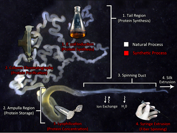 Graphical Overview: Biomimicry of the Spinning Process
Biomimicry of the natural spider silk production pathway: a route to manufacture synthetic silk. This image shows the major ampullate gland from the golden orb weaver, Nephila clavipes, and the components utilized for natural silk production (white text). The tail region synthesizes large quantities of silk proteins that are transported to the ampulla, a storage region for the spinning dope. This concentrated dope is extruded through the spinning duct where the solution experiences ion exchanges and dehydration prior to fiber extrusion. The biomimetic processes used in our laboratory are indicated by the red text. Recombinant silk production is generated using transgenic bacteria, followed by protein purification using chromatography. Next, the purified protein is subject to lyophilization to concentrate the material. Lastly, the protein is re-dissolved in HFIP and extruded from a syringe needle into an isopropanol bath.
1. Plasmid Construction and Bacterial Cell Culture Preparation
Perform PCR using the desired spider silk cDNA and specific primer sets. Gel-extract and ligate the amplified cDNA into a prokaryotic expression vector e.g. pBAD/TOPO ThioFusion (Fig. 1A). This vector has an N-terminal thioredoxin tag to facilitate silk protein solubilization and a C-terminal 6x his-tag for protein purification. Transform the ligation products into competent E. coli cells.
Select colonies that contain the recombinant cloning vector and use one colony to inoculate 200 mL of sterile LB supplemented with ampicillin (Fig. 1B). Grow this culture overnight to saturation by shaking at 200 rpm in an orbital incubator at 37 °C.
Combine the 200 mL of saturated culture with 800 mL of fresh LB culture. Induce spider silk protein expression for 4 hours by adding 0.2% arabinose (w/v). Make sure to keep the culture under antibiotic selection.
Pellet the cells at 16,000x g for 10 minutes at 4 °C (Fig. 1C). For simplicity, pellet the entire volume in one container. Multiple centrifugation steps may be necessary depending upon the volume capacity of the centrifugation tubes. If necessary, decant the liquid volume after spinning and re-pellet additional material to ensure the entire cell pellet is in one container. Cell pellets can be stored at -80 °C until needed.
Before disposing the spent culture media, add bleach or autoclave to sterilize.
2. Cell Lysis
Add 20 mL of 1x lysis buffer to the 1 L cell pellet (Fig. 2A). Make sure to resuspend the cell pellet completely.
Add lysozyme to a concentration of 1 mg/mL to promote further cell lysis. DNase can also be added at this step to digest chromosomal DNA to help reduce the viscosity of the solution. Place the sample on an orbital shaker and gently rock for 20 min.
Sonicate the solution at maximum for 1 minute.
To clarify the solution, centrifuge at 16,000x g for 10 minutes at 4 °C (Fig. 2B).
3. Protein Purification: Ni-NTA Affinity Column Chromatography
Remove the supernatant and transfer it into a clean 25 mL chromatography column. Make sure the supernatant is non-viscous and clear. If the solution is viscous and cloudy, add more DNase or sonicate and/or re-pellet the supernatant (repeat steps 2.3-2.4).
Add 1 mL of Ni-NTA slurry (0.5 mL beads) into the column. Tightly secure the cap and stopcock, and then set on a rocker to equilibrate for 1 hour to allow binding of the 6x his-tag to the Ni-NTA beads (Fig. 3A).
Set the column upright on a stand and allow the Ni-NTA beads to settle for approximately 2 minutes. A light blue layer can be seen at the bottom when the beads are completely settled.
Remove the cap and allow the solution to flow through the stopcock. Collect this solution for further analysis (Fig. 3B).
Add 20 mL of 1x wash buffer and allow the beads to settle. Open the stopcock and allow the solution to flow through. Collect this solution in four 5 mL aliquots for further analysis. Note: Additional wash volumes can be used to reduce contaminating proteins; however, there is a possibility of a decrease in final protein yield.
Add 20 mL of 1x elution buffer and allow the resin to settle. Open the stopcock and allow the solution to flow through. Collect this solution in four 5 mL aliquots for further analysis. Note: Additional elution volumes can be collected from the Ni-NTA resin if the elution is not completed.
Samples may be stored in 4 °C or -80 °C for short- or long term storage, respectively.
Size-fractionate the samples using SDS-PAGE analysis. Visualize the proteins with silver or Coomassie Brilliant Blue R-250 (Fig. 3C). Only pure fractions should be used for the following steps. Note: Western blot analysis can be used to confirm the identity of the purified protein.
4. Dialysis and Lyophilization
Dialyze the samples against at least 100x the sample volume (use deionized water) for 2 days. Change the water solution every 6 hours to remove all salts. Note: The molecular weight size cut-off of the dialysis tubing depends on the size of the recombinant silk protein.
Weigh six 1.5 mL empty microfuge tubes and record their masses. It may be useful to puncture small holes or slits on the caps of the tubes prior to weighing for freeze drying to facilitate lyophilization (Fig. 4A).
After dialysis, transfer 1 mL of the dialyzed sample into each of the 6 pre-weighed microfuge tubes (Fig. 4B). Flash freeze using liquid nitrogen and dry the samples down using a freeze dryer (Fig. 4C).
Once dry, transfer another 1 mL of the dialysis sample into each of the six tubes. Repeat until the entire dialysis sample has been dried down in the microfuge tubes.
Freeze dried samples can be stored at -80 °C for long term storage.
5. Spinning Dope Preparation
Weigh each of the microfuge tubes containing the dried protein powder. Subtract the initial mass of the empty tubes to obtain total dry protein mass. Note: Depending upon protein yield, you may need to purify additional material for the spinning process.
Calculate the volume of Hexafluoroisopropanol (HFIP) to add to each tube to obtain 200 mg/mL to 500 mg/mL, or 20% to 50% weight per volume. Add the appropriate amount of HFIP into each tube (Fig. 4D). Note: HFIP is highly volatile and toxic, pipette carefully and cap the tube as soon as possible. HFIP should be handled underneath a safety hood.
Parafilm the tubes and place on a rocker to solubilize the protein. Vortex and centrifuge occasionally to facilitate solubilization. This may take up to 2 days.
6. Syringe Preparation and Apparatus Setup
Load at least 25 μL of the solubilized spinning dope into the syringe. Make sure there are no aggregates present as it may clog the syringe. Note: This sample is incredibly viscous, so take care when pipetting.
Push the dope to the front of the syringe vertically, removing all air bubbles (Fig. 5A). Note: Air bubbles create inconsistencies in the fiber.
Lock the syringe to the pump. Raise a 400 mL beaker filled with 95% isopropanol up so the tip of the syringe is just breaking the surface of the alcohol (Fig. 5B).
Set the syringe pump to 15 μL/min and start the program. Allow the as-spun fiber to sit in the isopropanol for 20 minutes to fully equilibrate. Note: These fibers can still be used by MS/MS analysis to confirm the identity of the proteins in the fibers.
7. Post-spin Draw and Sample Collection
Apply double-sided tape to both sides of the comb on the spooling device. The spooling device was created from gluing metal combs to a digital caliper (Fig. 6A). Attach the spooling device to a motor (Fig. 6B). We recommend spooling the threads at 2 rpm. Note: faster spooling rates result in large amounts of variation in fiber quality and reproducibility.
Using forceps gently grab one end of the fiber and slowly pull it out of the isopropanol, attaching it to the edge of one of the comb arms on the spool (Fig. 6C). The next few steps should be done without a stoppage to prevent the fibers from drying out.
Turn on the motor and gently guide the fiber onto the spooling device. Note: During spooling, do not allow the fiber to double up and stack on top of each other.
Once the entire fiber is spooled, detach the spool from the motor and apply glue to the edge of each silk fiber on the double sided tape (Fig. 6D). This fastens the spider silk onto the apparatus. Note: By applying the glue to the double-sided tape prior to post-spin drawing, it prevents the entire fiber from slipping and allows for selective stretching of the interior segments of the fibers within the caliper arms.
Attach the spool to the linear actuator (Fig. 7A). Record the initial length of the fibers using the caliper. Note that this is the internal length of the fiber; it does not include the length glued and wrapped around the spool.
Lower the spool into a 75% isopropanol bath. Allow the fibers to equilibrate for 10 minutes. Note: Other dehydrating solutions can be used for the spinning process, such as methanol, acetone and ammonium sulfate.
Set the linear actuator speed to 1.5 mm/sec. Based on the initial length, calculate the final length for the desired post-spin draw ratio. The amount stretched can be controlled based on the speed or the length, depending on the set up. For example, with an initial length of 15 mm and a desired post-spin draw ratio of 3x, the final length should be 45 mm. This can also be calculated as powering the linear actuator for 20 seconds at a rate of 1.5 mm/sec.
Once the desired post spin draw is complete, slowly raise the spool out of the isopropanol. Allow the droplets of isopropanol to dry for 1 minute, and then collect samples (Fig. 7B). Samples should be mounted on cardstock or foil frames for testing purposes.
If further post spin draw ratios are desired, lower the spool back into the 75% isopropanol bath. Allow the fibers to equilibrate for 10 minutes, and then proceed to the next post spin draw ratio.
8. Tensile Testing
Allow the collected samples to equilibrate to the standard lab environment for at least 1 hour before mechanical testing. The humidity and temperature should be recorded as they may affect the fiber's mechanical properties. Standard humidity and temperature conditions should be approximately 40% and 25 °C, respectively.
Glue the edges of the cardstock or foil to secure the fiber on the frame. Take note of the size of the opening of the frame. This is the initial length of your tested fiber. A 1 inch (25.4 mm) opening frame is shown here (Fig. 8A).
Using a light microscope with a 100x or greater magnification, take diameter measurements along the longitudinal fiber axis. At least 3 measurements should be recorded. The higher the magnification used and the more measurements taken, the better the accuracy.
Secure the frame to a tensometer mechanical loading frame (Fig. 8B). Cut the frame on both sides so the tension is only running through the fiber. Tare the tensometer and collect the data. A standard strain rate of 2% per second is recommended.
Using the data collected and the average diameter, a stress strain curve can be plotted.
The broken fiber can now be mounted on a scanning electron microscope (SEM) stub for morphological analyses and break point diameter measurements. The fiber segment away from the break point can be used to estimate and check the initial diameter measured by the light microscope.
9. Representative Results
From step 3, the different fractions should be analyzed by SDS-PAGE analysis and the proteins visualized with silver or Coomassie Brilliant Blue R-250. From a standard Ni-NTA column conditions, elution fractions with >90% purity can be obtained (Fig. 9). Small contaminating proteins can be further removed by extensive dialysis. Using 25 μL of spinning dope at 20% (w/v), at least 30 separate fiber samples can be collected from the continuous wound fiber on the spool (assumes an initial length of 13 mm is used). The mechanical properties can be analyzed by tensometer tests (Fig. 10). Depending on the recombinant silk protein used for the spinning process, the maximum post spin draw ratios will need to be empirically determined. In general, post spin draw ratios of 4.0x can be achieved without fiber failure (Fig. 10). Spun fibers, before or after post spin draw, can be analyzed with a scanning electron microscope to visualize the ultrastructure (Fig. 11A,B). Spun fibers can also be used for mechanical testing, displaying results that with low variation within a post spin draw ratio sample group (Fig. 10).
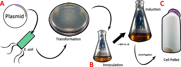 Figure 1. Expression of the spider silk cDNA in bacteria. A) The pBAD TOPO/Thio vector containing the spider silk cDNA of interest is transformed into competent E. coli cells. B) A single colony is inoculated into 200 mL of LB and grown to saturation overnight. Following inoculation, 800 mL of fresh LB is added and the culture is induced for expression using arabinose. C) At the conclusion of induction, the culture is pelleted by centrifugation. Click here to view larger figure.
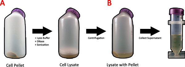 Figure 2. Lysis of bacterial cells after spider silk protein induction. A) Twenty milliliters of 1x lysis buffer and DNase is added to the cell pellet and placed on an orbital shaker and sonicated to lyse the cells. B) The cell lysate is spun in a centrifuge to clear the supernatant of cellular debris, and the supernatant is collected. Click here to view larger figure.
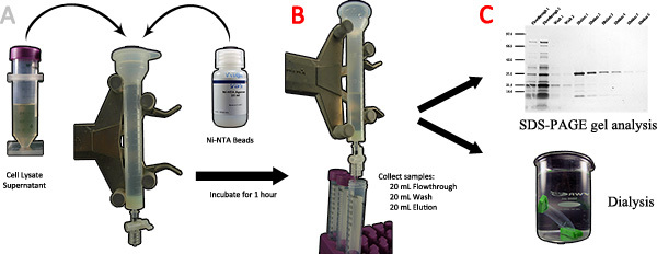 Figure 3. Purification of spider silk recombinant proteins using affinity chromatography. A) The cell lysate supernatant and Ni-NTA beads are added to a chromatography column and incubated for 1 hour. B) After the flowthrough is collected, 20 mL of wash buffer and 20 mL of elution buffer are used in sequence and collected in 5 mL fractions. C) The different fractions are analyzed by SDS-PAGE; the pure samples containing the target protein are transferred to a dialysis bag and dialyzed against DI water to completion. Click here to view larger figure.
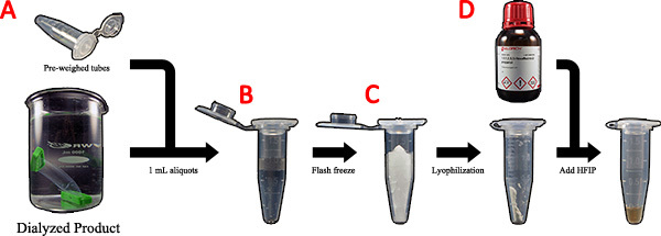 Figure 4. Preparation of the purified spider silk protein for wet-spinning. A) The dialyzed product is transferred to pre-weighed centrifuge tubes in 1 mL aliquots. B) The 1 mL aliquots are flash frozen with liquid nitrogen. C) The frozen samples are lyophilized and more dialysis sample is added. D) Dried mass is calculated and HFIP is added to the dry powder to produce a 20% (w/v) spinning dope. Click here to view larger figure.
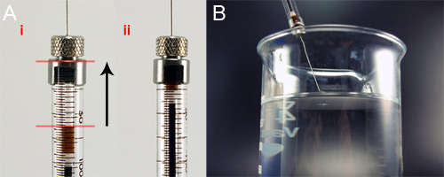 Figure 5. Loading of the spinning dope into the glass syringe for wet-spinning. A) While holding the syringe vertically, the spinning dope is pushed to the top of the syringe column, removing air bubbles. B) The loaded syringe is attached to the syringe pump and lowered into the 95% isopropanol bath so the tip is just breaking the surface of the bath.
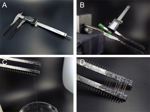 Figure 6. Spooling of the synthetic spider silk fibers onto a custom reeling device. A) The spooling device is constructed from a digital caliper with attached metal combs. Double sided tape is applied to both sides of the comb to attach the fiber ends. B) The spool is attached to the slow speed motor using an alligator clip. C) The fiber is slowly pulled from the alcohol bath and wound around the spool. D) Glue is applied to the edge of each fiber segment to hold them in place. Shown are two different fibers spun from different proteins.
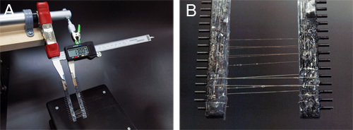 Figure 7. Post-spin draw of the synthetic fibers using a homemade apparatus. A) The spooling device is attached to the linear actuator setup using alligator clips. B) After a post spin draw step, the spool is lifted from the bath. Isopropanol droplets are allowed to evaporate before fiber collection.
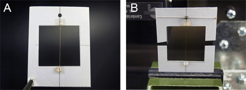 Figure 8. Mounting of the synthetic silk fibers onto a cardstock for mechanical studies. A) Collected fibers are mounted on cardstock frames with a 1" x 1" cutout. The fibers are initially held in place with double sided tape, and then fixed with glue. B) The cardstock frame is fixed onto a tensometer. The sides are then cut so the tension is only running though the fiber.
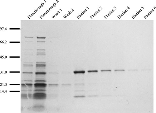 Figure 9. Size fractionation of purified recombinant MaSp1 protein fractions using SDS-PAGE analysis followed by visualization with silver staining. Protein ladder is depicted in kDa. The two wash samples show non-specific binding to the beads, while the elution samples reveal the need for 6 collections to ensure total protein recovery.
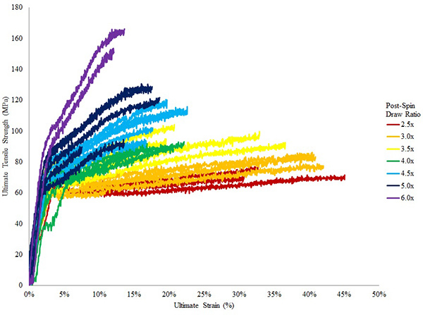 Figure 10. Stress strain curves of fibers spun from recombinant TuSp1 proteins.8 Colors show fibers that were subject to different post spin draw ratios, ranging from 2.5x to 6x. Fibers show low variation within their ratio group; as post spin draw ratios increase, the strength of the fiber is increased while extensibility is decreased.
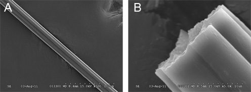 Figure 11. Scanning electron microscopy images of fibers spun from recombinant TuSp1 proteins. A) At 500x magnification, the smooth external surface can be seen. B) At 5000x, the dense interior core can be observed from a natural break of fiber.
Discussion
Synthetic fibers spun from this methodology are mechanically on the same order of magnitude compared to the natural fibers. By decreasing the amount of human error by mechanizing the spooling and post spin draw processes, the experimental variation between samples are more controlled and greatly reduced.
Our methodology offers the potential to investigate the mechanical properties of other fibers that are spun from recombinant proteins encoded from the cDNAs of other members of spider gene family. Potentially, it could determine the mechanical role of different protein modules within a fibroin, or between the different fibroin types.23 It also allows for the testing of silk fibers as composites, as more than one silk protein or other molecules can be combined or added and spun as a protein mixture.
This spinning methodology is a platform for other laboratories to easily expand upon, as the apparatuses can be constructed in a facile manner. This also allows for adjusting parameters along each step to optimize or customize the design of specific fibers with unique mechanical properties. As the need for green biomaterials for the future increases, this methodology can be adapted to produce fibers that serve a host of next generation applications.
Disclosures
No conflicts of interest declared.
Acknowledgments
This work was supported by NSF RUI Grants MCB-0950372 and DMR-1105310 entitled "Molecular Characterization of Black Widow Spider Silks and Mechanical Behavior of Spider Glue Silks," respectively.
References
- Gosline JM, Guerette PA, Ortlepp CS, Savage KN. The mechanical design of spider silks: from fibroin sequence to mechanical function. J. Exp. Biol. 1999;202:3295–3303. doi: 10.1242/jeb.202.23.3295. [DOI] [PubMed] [Google Scholar]
- Foelix R. Biology of spiders. New York: Oxford University Press; 1996. [Google Scholar]
- Vollrath F, Knight DP. Liquid crystalline spinning of spider silk. Nature. 2001;410:541–548. doi: 10.1038/35069000. [DOI] [PubMed] [Google Scholar]
- Spiess K, Lammel A, Scheibel T. Recombinant spider silk proteins for applications in biomaterials. Macromol. Biosci. 2010;10:998–1007. doi: 10.1002/mabi.201000071. [DOI] [PubMed] [Google Scholar]
- Stark M, Grip S, Rising A, Hedhammar M, Engstrom W, Hjalm G, Johansson J. Macroscopic fibers self-assembled from recombinant miniature spider silk proteins. Biomacromolecules. 2007;8:1695–1701. doi: 10.1021/bm070049y. [DOI] [PubMed] [Google Scholar]
- Lazaris A, Huang Y, Zhou JF, Duguay F, Chretien N, Welsh EA, Soares JW, Karatzas CN. Spider Silk Fibers Spun from Soluble Recombinant Silk Produced in Mammalian Cells. Science. 2002;295:472–476. doi: 10.1126/science.1065780. [DOI] [PubMed] [Google Scholar]
- Teule F, Cooper AR, Furin WA, Bittencourt D, Rech EL, Brooks A, Lewis RV. A protocol for the production of recombinant spider silk-like proteins for artificial fiber spinning. Nat. Protoc. 2009;4:341–355. doi: 10.1038/nprot.2008.250. [DOI] [PMC free article] [PubMed] [Google Scholar]
- Gnesa E, Hsia Y, Yarger JL, Weber W, Lin-Cereghino J, Lin-Cereghino G, Tang S, Agari K, Vierra C. Conserved C-Terminal Domain of Spider Tubuliform Spidroin 1 Contributes to Extensibility in Synthetic Fibers. Biomacromolecules. 2011. [DOI] [PubMed]
- Hayashi CY, Shipley NH, Lewis RV. Hypotheses that correlate the sequence, structure, and mechanical properties of spider silk proteins. Int. J. Biol. Macromol. 1999;24:271–275. doi: 10.1016/s0141-8130(98)00089-0. [DOI] [PubMed] [Google Scholar]
- Xu M, Lewis RV. Structure of a protein superfiber: Spider Dragline Silk. Proc. Natl. Acad. Sci. 1990;87:7120–7124. doi: 10.1073/pnas.87.18.7120. [DOI] [PMC free article] [PubMed] [Google Scholar]
- Hayashi CY, Blackledge TA, Lewis R. Molecular and mechanical characterization of aciniform silk: uniformity of iterated sequence modules in a novel member of the spider silk fibroin gene family. Mol. Biol. Evol. 2004;21:1950–1959. doi: 10.1093/molbev/msh204. [DOI] [PubMed] [Google Scholar]
- Lazaris A, Arcidiacono S, Huang Y, Zhou JF, Duguay F, Chretien N, Welsh EA, Soares JW, Karatzas CN. Spider silk fibers spun from soluble recombinant silk produced in mammalian cells. Science. 2002;295:472–476. doi: 10.1126/science.1065780. [DOI] [PubMed] [Google Scholar]
- Arcidiacono S, Mello C, Kaplan D, Cheley S, Bayley H. Purification and characterization of recombinant spider silk expressed in Escherichia coli. Appl. Microbiol. Biotechnol. 1998;49:31–38. doi: 10.1007/s002530051133. [DOI] [PubMed] [Google Scholar]
- Menassa R, Zhu H, Karatzas CN, Lazaris A, Richman A, Brandle J. Spider dragline silk proteins in transgenic tobacco leaves: accumulation and field production. Plant Biotechnology Journal. 2004;2:431–438. doi: 10.1111/j.1467-7652.2004.00087.x. [DOI] [PubMed] [Google Scholar]
- Scheller J, Guhrs KH, Grosse F, Conrad U. Production of spider silk proteins in tobacco and potato. Nat. Biotechnol. 2001;19:573–577. doi: 10.1038/89335. [DOI] [PubMed] [Google Scholar]
- An B, Hinman MB, Holland GP, Yarger JL, Lewis RV. Inducing beta-sheets formation in synthetic spider silk fibers by aqueous post-spin stretching. Biomacromolecules. 2011;12:2375–2381. doi: 10.1021/bm200463e. [DOI] [PMC free article] [PubMed] [Google Scholar]
- Elices M, Guinea GV, Plaza GR, Karatzas C, Riekel C, Agullo-Rueda F, Daza R, Perez-Rigueiro J. Bioinspired Fibers Follow the Track of Natural Spider Silk. Macromolecules. 2011;44:1166–1176. [Google Scholar]
- Scheller J, Guhrs KH, Grosse F, Conrad U. Production of spider silk proteins in tobacco and potato. Nature Biotechnology. 2001;19 doi: 10.1038/89335. [DOI] [PubMed] [Google Scholar]
- Kojic N, Kojic M, Gudlavalleti S, McKinley G. Solvent removal during synthetic and Nephila fiber spinning. Biomacromolecules. 2004;5:1698–1707. doi: 10.1021/bm034280x. [DOI] [PubMed] [Google Scholar]
- Jeffery F, La Mattina C, Tuton-Blasingame T, Hsia Y, Gnesa E, Zhao L. Microdissection of Black Widow Spider Silk-producing Glands. J. Vis. Exp. 2011. p. e2382. [DOI] [PMC free article] [PubMed]
- Blasingame E, Tuton-Blasingame T, Larkin L, Falick AM, Zhao L, Fong J, Vaidyanathan V, Visperas A, Geurts P, Hu X, La Mattina C, Vierra C. Pyriform spidroin 1, a novel member of the silk gene family that anchors dragline silk fibers in attachment discs of the black widow spider, Latrodectus hesperus. J. Biol. Chem. 2009;284:29097–29108. doi: 10.1074/jbc.M109.021378. [DOI] [PMC free article] [PubMed] [Google Scholar]
- La Mattina C, Reza R, Hu X, Falick AM, Vasanthavada K, McNary S, Yee R, Vierra CA. Spider minor ampullate silk proteins are constituents of prey wrapping silk in the cob weaver Latrodectus hesperus. Biochemistry. 2008;47:4692–4700. doi: 10.1021/bi800140q. [DOI] [PubMed] [Google Scholar]
- Hsia Y, Gnesa E, Jeffery F, Tang S, Vierra C. Spider Silk Composites and Applications. In: Cuppoletti J, editor. Metal, Ceramic and Polymeric Composites for Various Uses. Vol. 2. InTech; 2011. pp. 303–324. [Google Scholar]


